


Installation/Operating Instructions
Invented for life
MODELS
Bosch 17e
Bosch 21e
Bosch 25e
Bosch 26e
(YS1770RA series, YS2170RA series, YS2670RABZ, YS2670RA series)
INSTALLATION MANUAL
This appliance must be installed in accordance with the manufacturer’s installation instructions, AS5601,
AS/NZS3500.4, AS3000 wiring regulations and all Local Building, Water and Gas fitting regulations.
To be installed and serviced only by an authorised person
This appliance is not suitable for use as a pool heater
The “authorised installing person” is responsible for :
1.Correct commissioning of this appliance.
2.Ensure unit performs to the specifications stated on the rating label.
3.Demonstrate operation of unit to customer before leaving.
4.Hand these instructions to customer.
Failure to install this appliance in accordance with these installation instructions may void warranty
SAR8512-7 |
1 |
|
Rev. 10/11 |
||
|
*SAR8512 C*

Installation/Operating Instructions
Invented for life
INDEX
Page Number
INTRODUCTION |
3 |
DIMENSIONS |
4 |
TECHNICAL DATA |
5 |
APPLIANCE LOCATION |
6 |
COMPONENT DETAILS |
7 |
GAS CONNECTION |
9 |
COLD WATER CONNECTION |
9 |
HOT WATER CONNECTION |
10 |
ELECTRICAL CONNECTION |
10 |
PRE-SET TEMPERATURE |
10 |
TEMPERATURE SELECTOR PAD INSTALLATION |
11 |
TEMPERATURE SELECTOR PAD WIRING |
11 |
TEMPERATURE CONTROL OPERATION |
12 |
COMMISSIONING AND TESTING |
12 |
TEMPERATURE SETTING |
13 |
USER SAFETY INSTRUCTIONS |
15 |
IN CASE OF DIFFICULTIES |
15 |
Manufacturer’s Warranty |
17 |
2

Installation/Operating Instructions
Invented for life
This Bosch water heater is an external, electronically controlled gas water heater. This Bosch appliance is supplied set to operate without temperature selector pads at a constant 55°C outlet temperature. To set the appliance to a different temperature, refer to page 13 for details.
Available as optional extras are Main, Bathroom or Sub temperature selector pads.
Only one Main controller and one Bathroom controller can be connected to the appliance along with up to 2 x Sub-controllers.
The bathroom and sub temperature selector pads have a maximum temperature setting of 50°C for safety. To ensure compliance with Australian Standard AS/NZS 3500.4, in the bathroom area, this may be achieved by using a Bosch appliance limited to 50°C or using a Bosch appliance with a delivery temperature greater than 50°C and installed with a tempering valve (high performance). In New Zealand, please refer to the New Zealand Building Code and all other applicable electrical, gas fitting and plumbing codes.
Before installing this appliance, carefully check that all packing materials have been removed and that the appliance is correct for the gas supply to which it is to be connected
3

Installation/Operating Instructions
Invented for life
DIMENSIONS YS1770RA series, YS2170RA series
Perspective drawing from upper of appliance |
|
|
||||
|
|
255 |
|
|
|
|
|
|
178 |
|
|
|
|
|
|
109 |
|
|
|
|
40 |
37 |
|
40 |
57 |
|
|
|
|
|
|
|||
97 |
|
|
|
|
|
|
|
|
|
|
Gas connection R3/4 |
|
|
Outlet-water connection R3/4 |
|
|
|
|
|
|
Inlet-water connection R3/4 |
|
|
Power cable intaking hole |
|
||
|
120 |
|
|
|
|
|
|
|
|
|
|
|
|
7-φ7.2 hole |
85 |
|
10 |
170 |
11 |
|
Installation hole of wall |
50 |
10 |
|
|
|
|
(Installed with three holes) |
|
|
|
|||
|
|
|
|
|||
|
|
|
31 |
|
|
|
|
|
|
542 |
487 |
|
520 |
|
|
120 |
|
|
|
|
|
|
60 |
|
|
|
|
|
L |
YS1770RA series |
178 |
YS2170RA series |
214 |
338 |
|
|
|
350 |
|
|
334 |
Flue terminal |
L |
|
510512 |
flame installation pich) |
|
|
(PS |
|
Bottom of case
25
42
Air-inlet
Bottom of case
7-φ7.2 hole |
84 |
Installation hole of wall (Installed with two holes)
10
|
48 44 |
308 320 |
10 |
133 |
(PS flame installation pich) |
Inlet-water connection
Water drain valve (Water filter)
Outlet-water connection
Pressure relife valve and Water drain valve
Earth connection screw
49
Gas connection
Power cable intaking hole
DIMENSIONS YS2670RA series, YS2670RABZ
Perspective drawing from upper of appliance |
|
|
|
|
|
|
||||
|
|
268 |
|
|
|
|
|
|
|
|
|
|
178 |
|
|
|
|
|
|
|
|
|
|
109 |
|
|
|
|
|
|
|
|
40 |
37 |
|
40 |
47 |
|
|
|
|
|
338 |
|
|
|
|
|
|
|
||||
97 |
|
|
|
|
|
|
|
|
|
|
Outlet-water connection R3/4 |
|
|
|
Gas connection R3/4 |
|
|
|
|
|
|
|
|
|
|
|
|
|
|
|
|
|
Inlet-water connection R3/4 |
|
|
Power cable intaking hole |
|
|
|
|
|
||
|
120 |
|
|
|
|
|
|
|
350 |
|
|
|
|
|
|
|
|
|
|
||
7-φ7.2 hole |
85 |
|
10 |
170 |
11 |
|
|
|
334 |
|
Installation hole of wall |
50 |
10 |
|
|
|
|
Flue terminal |
253 |
||
(Installed with three holes) |
|
|
|
|
||||||
|
|
|
|
|
|
|
|
|||
|
|
|
31 |
|
|
|
|
|
pich) |
|
|
|
120 |
622 |
567 |
|
|
600 |
590592 |
flame installation |
|
|
|
|
|
|
|
|
|
(PS |
|
|
|
|
60 |
|
|
|
|
|
|
|
|
Bottom of case
25
42 |
Air-inlet
Bottom of case
10
7-φ7.2 hole |
84 |
Installation hole of wall
(Installed with two holes)
10 |
133 |
48 44 |
318 320 |
49 |
|
|
Inlet-water connection |
(PS flame installation pich) |
|
|
|
|
Gas connection |
|
|
|
Water drain valve (Water filter) |
|
Outlet-water connection
Pressure relife valve and Water drain valve
Power cable intaking hole
Earth connection screw
4

Installation/Operating Instructions
Invented for life
TECHNICAL DATA
Nominal hourly gas consumption by proportional gas control:
|
|
Natural Gas |
|
LP Gas |
|
|
|
|
|
|
|
|
|
|
|
|
|
|
|
|
|
|
|
|
|
17e |
|
135 Mj/hr |
|
135 Mj/hr |
|
|
|
|
|
|
|
|
|
|
|
|
|
|
|
|
|
|
|
|
|
21e |
|
170 Mj/hr |
|
170 Mj/hr |
|
|
|
|
|
|
|
|
|
|
|
|
|
|
|
|
|
|
|
|
|
25e |
|
200 Mj/hr |
|
200 Mj/hr |
|
|
|
|
|
|
|
|
|
|
|
|
|
|
|
|
|
|
|
|
|
26e |
|
200 Mj/hr |
|
200 Mj/hr |
|
|
|
|
|
|
|
|
|
|
|
|
|
|
|
|
|
|
|
|
|
Test Point Pressure: |
|
|
|
|
|
|
|
|
|
|
|
|
|
|
|
|
|
|
|
|
|
|
|
|
|
Model |
|
Natural Gas |
|
Natural Gas |
|
|
LP Gas |
|
|
LP Gas |
||
|
Max (kPa) |
|
Min (kPa) |
|
|
Max (kPa) |
Min (kPa) |
|||||
|
|
|
|
|
||||||||
|
|
|
|
|
|
|
|
|
|
|
|
|
YS1770RA series |
|
.67 |
|
.26 |
|
|
.78 |
|
.23 |
|||
|
|
|
|
|
|
|
|
|
|
|
|
|
YS2170RA series |
|
.69 |
|
.21 |
|
|
.91 |
|
.23 |
|||
|
|
|
|
|
|
|
|
|
|
|
||
YS2670RABZ |
|
.72 |
|
.19 |
|
|
.80 |
|
.22 |
|||
|
|
|
|
|
|
|
|
|
|
|
|
|
YS2670RA series |
|
.72 |
|
.19 |
|
|
.80 |
|
.22 |
|||
|
|
|
|
|
|
|
|
|
|
|
|
|
|
|
|
|
|
|
|
|
|
|
|
||
Water heating capacity |
|
17e |
|
|
|
21e |
|
25e |
|
26e |
||
|
|
|
|
|
|
|
|
|
|
|||
Litres a minute raised 25°C |
|
17 |
|
21 |
|
26 |
|
26 |
||||
|
|
|
|
|
|
|
|
|
|
|||
Maximum Inlet Water Pressure |
|
|
1000 kPa |
|
|
|
||||||
Input voltage single phase 50Hz |
|
|
AC240/230 Volt |
|
|
|||||||
Maximum output current |
|
|
1 Amp |
|
|
|
||||||
AGA Approval certificate number |
|
|
7032 |
|
|
|
|
|||||
Inlet gas connection male thread |
|
|
20mm |
|
|
|
||||||
Cold water connection male thread |
|
|
20mm |
|
|
|
||||||
Hot water connection male thread |
|
|
20mm |
|
|
|
||||||
Relief valve pressure setting |
|
|
1600 kPa |
|
|
|
||||||
DATA PLATE
Fitted inside of cabinet
GAS TYPE
The gas type is nominated on a temporary label located on the front cover, and on the data plate located inside of cabinet. The gas type is the gas on which this appliance is designed to operate.
DO NOT OPERATE WITH ANY OTHER GAS TYPE.
WARNING LABELS
Located on the right side of the cabinetPLEASE READ THESE LABELS CAREFULLY!
5
Installation/Operating Instructions
Invented for life
POSITION FOR INSTALLATION
The heater must be installed by using a fixing method sufficient to hold the 21Kg weight of unit (see the technical sheet for dimensions of mounting brackets and positions) N.B.: On combustible surfaces e.g. weatherboards etc. it is not required to install a fire proof back board.
APPLIANCE LOCATION
(1)This water heater is approved for outdoor installation only.
(2)Do not install this water heater with any modification or alteration.
(3)Do not install this water heater indoors or in an enclosed space .
WARNING: FLUE OUTLET MUST BE FREE FROM ANY COMBUSTIBLE MATERIAL.
CLEARANCES FOR FLUE TERMINAL (front of heater)
The location of the flue terminal must comply with the clearances shown on this page. If you are unsure about clearances not indicated here, in general refer to AS5601, or your local authority. In Western Australia refer to the SECWA rules and regulations.
|
|
|
|
|
|
|
|
|
|
|
|
|
|
|
|
|
|
|
|
|
|
|
|
|
|
|
|
|
|
|
|
|
|
|
|
|
|
|
|
|
|
|
|
|
|
|
|
|
|
|
|
|
a |
|
|
|
|
|
|
|
|
|
||
|
|
|
|
|
|
|
|
|
|
|
|
|
|
|
|
|
|
|
|
|
|
|
|
|
|
|
|
|
|
|
|
|
|
|
|
|
|
|
|
|
|
|
|
|
|
|
|
|
|
|
|
|
|
|
|
|
|
|
|
|
|
|
|
|
|
|
|
|
|
|
|
|
|
|
|
|
|
|
|
|
|
|
|
|
|
|
|
|
|
|
|
|
|
|
|
|
|
|
|
|
|
|
|
|
|
|
|
|
|
|
|
|
|
|
|
|
|
|
|
|
|
|
|
|
|
|
|
|
|
|
|
|
|
|
|
|
|
|
|
|
|
|
j |
|
|
|
|
|
|
|
|
|
|
|
|
|
|
|
|
|
|
|
|
T |
|
|
|
|
|
|
|
|
|
|
|
|
|
|
|
|
|
|
|
|
|
c |
||||||||
|
|
|
|
|
|
|
|
|
|
|
|
|
|
|
|
|
|
|
|
|
|
|
|
|
|
|
|
|
|
|
|
|
|
|
|
|
|
|
|
|
|
|
|
|
|
|
|
|
|
|
|
|
|
|
|
|
|
|||||||
|
|
|
|
|
|
|
|
|
|
|
|
|
|
|
|
|
|
|
|
|
|
|
|
|
|
|
|
|
|
|
|
|
|
|
|
|
|
|
|
|
|
|
|
|
|
|
|
|
|
|
|
|
|
|
|
|
|
|
|
|
|
|||
|
|
|
n |
|
|
|
W |
|
|
|
|
|
|
|
|
|
j |
|
|
|
|
|
j |
|
|
h |
|
|
|
|
h |
|
e |
|
|
|
e |
|
|
|
|
|
|
|
|
|
|
|
|
|
|
|
|
|
|
|
||||||||
|
|
|
|
|
|
|
|
|
|
|
|
|
|
|
|
|
|
|
|
|
|
|
|
|
|
|
|
|
|
|
|
|
|
|
|
|
|
|
|
|
|
|
|
|
|
|
|
|
||||||||||||||||
|
|
|
|
|
|
|
|
|
|
|
|
|
|
|
|
|
|
|
|
|
|
|
|
|
|
|
|
|
|
|
|
|
|
|
|
|
|
|
|
|
|
|
|
|
|
|
|
|||||||||||||||||
|
|
|
|
|
|
|
|
|
|
|
|
|
|
|
|
|
|
|
|
|
|
|
|
|
|
|
|
|
|
|
|
|
|
|
|
|
|
|
|
|
|
|
|
|
|
|
|
|
|
|
|
|
|
|
|
|
||||||||
f |
|
|
|
|
|
|
|
|
|
|
|
|
|
|
k |
|
door |
|
|
|
|
|
h |
|
|
|
P |
|
|
|
|
|
|
|
|
|
d |
|
|
|
|
|
|
g |
||||||||||||||||||||
|
|
|
|
|
|
|
|
|
|
|
|
|
|
|
|
|
|
|
|
|
|
|
|
|
|
|
|
|
|
|
||||||||||||||||||||||||||||||||||
|
|
|
|
|
|
|
|
|
|
|
|
|
|
|
|
|
|
|
|
|
|
|
|
|
|
|
|
|
|
T |
|
|
|
|
|
|
|
d |
|
|
|
|
|
|
|
|
|
|
|
|
||||||||||||||
|
|
|
|
|
|
|
|
|
|
|
|
|
|
|
|
|
|
|
|
|
|
|
|
|
|
|
|
|
|
|
|
|
|
|
|
|
|
|
|
|
|
|
|
|||||||||||||||||||||
|
|
|
|
|
|
|
|
|
I |
|
|
|
|
|
|
|
|
|
|
|
|
|
|
|
|
|
|
|
|
|
|
|
|
|
|
|
|
|
|
|
|
|
M |
|
b |
|||||||||||||||||||
|
|
|
|
|
|
c |
|
|
|
|
|
|
|
|
|
|
|
|
|
|
|
|
|
|
|
|
|
|
|
|
|
|
|
g |
|
|
|
|
|
|
|
|
|
|
|
|
|
|
|
|
|
|
|
|
||||||||||
|
|
|
|
|
|
|
|
|
|
k |
|
|
|
|
|
|
|
|
|
|
|
|
|
|
|
|
|
|
|
|
|
|
|
|
|
|
|
|
|
|
|
|
|
|
|
|
|
|
|
|
|
|
|
|
|
T |
||||||||
|
|
|
|
|
|
|
|
|
|
|
|
|
|
|
|
|
|
|
|
|
|
|
|
|
|
|
|
|
|
|
|
|
|
|
|
|
|
|
|
|
|
|
|
|
|
|
|
|
|
|
|
|
|
|
|
|
|
|
|
|
|
|
|
|
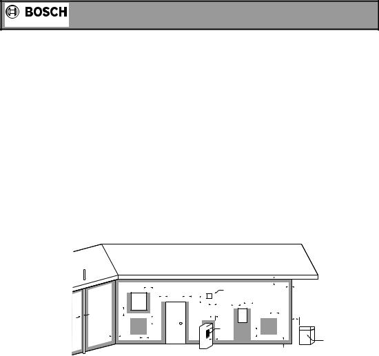
Use as a guide only. Refer to AS5601 or local gas fitting rules for specific locations
|
T=Flue terminal |
M=Gas meter |
|
|
Shaded area indicates |
|
|
|
|
|
|
|
|||||
|
I=Mechanical air inlet |
P=Electricity meter |
|
|
prohibited area |
|
|
|
|
|
|
|
|||||
|
|
or fuse box |
W=Window |
|
|
|||
|
|
|
|
|
|
|
||
Ref |
|
Item |
|
|
Minimum |
Clearance |
||
|
|
|
|
|
|
|
|
mm |
|
|
|
|
|
|
|
Natural |
Fan |
|
|
|
|
|
|
|
draft |
assisted |
a |
Below eaves,balconiesand other projections |
|
|
|
|
|||
|
Appliancesup to 50MJ/h input |
|
|
300 |
200 |
|||
|
Appliancesover 50 MJ/h input |
|
|
500 |
300 |
|||
b |
From the ground, above a balcony or other surface |
|
|
300 |
300 |
|||
c |
From a return wall or externalcorner |
|
|
|
|
|
500 |
300 |
d |
Froma gasmeter |
|
|
|
|
|
1000 |
1000 |
e |
From an electricity meter or fuse box (P) |
|
|
500 |
500 |
|||
f |
Froma drain pipe or soil pipe |
|
|
|
|
|
150 |
75 |
g |
Horizontally from any building structure or obstruction facing a flue |
|
500 |
500 |
||||
|
terminal |
|
|
|
|
|
|
|
h |
From any other flue terminal, cowl, or combustion air intake |
|
|
500 |
300 |
|||
j |
Horizontallyfrom an opening window, door, non-mechanicalair inlet. Or other |
opening |
|
|||||
|
into a building with the exception of sub floor ventilation |
|
|
|
|
|||
|
Appliancesup to 150 MJ/h |
|
|
|
|
|
500 |
300 |
|
Appliancesover 150MJ/hinput up to 200 MJ/h input |
|
|
1500 |
300 |
|||
|
Appliances over 200 MJ/h input up to 250 MJ/h input |
|
1500 |
500 |
||||
|
Appliances over 250 MJ/h input |
|
|
1500 |
1500 |
|||
|
All fan assistedflue appliancesin the direction of discharge |
|
|
1500 |
||||
k |
From a mechanicalair inlet, including spablower |
|
|
1500 |
1000 |
|||
n |
Verticallybelow an openablewindow, non-mechanicalair inlet, or any other |
opening into a |
|
|||||
|
building with the exception of sub-floor ventilation: |
|
|
|
|
|||
|
Spaceheatersup to 50 MJ/h |
|
|
150 |
150 |
|||
|
Other appliancesup to 50 MJ/h |
|
|
500 |
500 |
|||
|
Appliancesover 50 MJ/h and up to 150 MJ/h input |
|
|
1000 |
1000 |
|||
|
Appliancesover 150 MJ/h input |
|
|
1500 |
1500 |
|||
6
 Loading...