


ZEPHAIRE 240G PLUS
CONVECTION OVEN
INSTALLATION - OPERATION - MAINTENANCE
ZEPHAIRE 240G PLUS
FOURS À CONVECTION
MANUEL D'INSTALLATION - FONCTIONNEMENT - ENTRETIEN
BLODGETT OVEN COMPANY
www.blodgett.com
44 Lakeside Avenue, Burlington, Vermont 05401 USA Telephone (800) 331'5842, (802) 860'3700 Fax: (802)864'0183
PN 52898 Rev A (8/09)
E 2009 - G.S. Blodgett Corporation

IMPORTANT
WARNING: IMPROPER INSTALLATION, ADJUSTMENT, ALTERATION, SERVICE OR MAINTENANCE CAN CAUSE PROPERTY DAMAGE, INJURY OR DEATH. READ THE INSTALLATION, OPERATING AND MAINTENANCE INSTRUCTIONS THOROUGHLY BEFORE INSTALLING OR SERVICING THIS EQUIPMENT
AVERTISSEMENT: UNE INSTALLATION, UN AJUSTEMENT, UNE ALTÉRATION, UN SERVICE OU UN ENTRETIEN NON CONFORME AUX NORMES PEUT CAUSER DES DOMMAGES À LA PROPRIÉTE, DES BLESSURES OU LA MORT. LISEZ ATTENTIVE MENT LES DIRECTIVES D'INSTALLATION, D'OPÉRATION ET D'ENTRETIEN AVANT DE FAIRE L'INSTALLATION OU L'ENTRETIEN DE CET ÉQUIPEMENT.
INSTRUCTIONS TO BE FOLLOWED IN THE EVENT THE USER SMELLS GAS MUST BE POSTED IN A PROMINENT LOCATION. THIS INFORMATION MAY BE OBTAINED BY CONTACTING YOUR LOCAL GAS SUPPLIER.
LES INSTRUCTIONS À RESPECTER AU CAS OÙ L'UTILISATEUR PERÇOIT UNE ODEUR DE GAZ DOIVENT ÊTRE AFFICHÉES DANS UN ENDROIT BIEN VISIBLE. VOUS POUVEZ VOUS LES PROCURER AUPRÈS DE VOTRE FOURNISSEUR DE GAZ LOCAL.
FOR YOUR SAFETY
Do not store or use gasoline or other flammable vapors or liquids in the vicinity of this or any other appliance.
AVERTISSEMENT
Ne pas entreposer ni utiliser de l'essence ni d'autres vapeurs ou liquides inflam mables dans le voisinage de cet appariel, ni de tout autre appareil.
The information contained in this manual is important for the proper installation, use, and maintenance of this oven. Adherence to these procedures and instruc tions will result in satisfactory baking results and long, trouble free service. Please read this manual carefully and retain it for future reference.
Les informations données dans le présent manuel sont importantes pour installer, utiliser et entretenir correctement ce four. Le respect de ces instructions et procé dures permettra d'obtenir de bons résultats de cuisson et une longue durée de ser vice sans problèmes. Veuillez lire le présent manuel et le conserver pour pouvoir vous y reporter à l'avenir.
Errors: Descriptive, typographic or pictorial errors are subject to correction. Specifica tions are subject to change without notice.
Erreurs:Les erreurs de description, de typographie ou d'illustration font l'objet de corrections. Les caractéristiques sont sujettes à modifications sans préavis.

THE REPUTATION YOU CAN COUNT ON
UNE RÉPUTATION SUR LAQUELLE VOUS POUVEZ COMPTER
For over a century and a half, The Blodgett Oven Company has been building ovens and nothing but ovens. We've set the industry's quality standard for all kinds of ovens for every foodservice operation regardless of size, application or budget. In fact, no one offers more models, sizes, and oven applications than Blodgett; gas and electric, full'size, half'size, countertop and deck, con' vection, Cook'n Hold, Combi'Ovens and the industry's highest quality Pizza Oven line. For more information on the full line of Blodgett ovens contact your Blodgett representative.
Cela fait maintenant dessus un siècle et demi que Blodgett se spécialise dans la fabrication de fours. Nous avons établi les normes de qualité qui s'appli' quent dans l'industrie à tous les types de fours utilisés dans les services ali' mentaires, quel qu'en soit la taille, l'exploitation ou le budget. En fait, ni n'offre plus de modèles, de tailles et d'applications de fours que Blodgett. À gaz et électriques. De tailles différentes, sur plan de travail et superposables. Qu'il s'agisse de fours à convection, des modèles Cook'n Hold et Combi'Oven, ou de la gamme de fours à pizzas de la plus haute qualité offerte sur le marché. Pour de plus amples informations sur la gamme complète de fours Blodgett, veuillez contacter votre représentant Blodgett.
Model/Modèl:
Your Service Agency's Address: Adresse de votre agence de service:
Serial Number/Numéro de série:
Your oven was installed by/
Installateur de votre four:
Your oven's installation was checked by/
Contrôleur de l'installation de votre four:

Table of Contents/Table des Matières
Installation
Oven Description and Specifications . . . . 2
Delivery and Location . . . . . . . . . . . . . . . . . 3
Utility Connections -
Standards and Codes . . . . . . . . . . . . . . . . . 4
Oven Assembly . . . . . . . . . . . . . . . . . . . . . . 5
NSF Bolts . . . . . . . . . . . . . . . . . . . . . . . . . . 5
Leg Attachment . . . . . . . . . . . . . . . . . . . . . 6
Caster Assembly . . . . . . . . . . . . . . . . . . . . 6
Double Section Assembly . . . . . . . . . . . . 7
Oven Leveling . . . . . . . . . . . . . . . . . . . . . . 7
Ventilation . . . . . . . . . . . . . . . . . . . . . . . . . . . 8
Canopy Type Exhaust Hood . . . . . . . . . . 8
Direct Flue Arrangement . . . . . . . . . . . . . 9
Gas Connection . . . . . . . . . . . . . . . . . . . . . . 10
Electrical Connection . . . . . . . . . . . . . . . . . 13
Initial Startup . . . . . . . . . . . . . . . . . . . . . . . . . 14
Operation
Safety Information . . . . . . . . . . . . . . . . . . . . 15 Oven Control . . . . . . . . . . . . . . . . . . . . . . . . . 16 General Guidelines for Operating
Personnel . . . . . . . . . . . . . . . . . . . . . . . . . . . . 17 Suggested Times and Temperatures . . . . 18
Maintenance
Cleaning and Preventative Maintenance . 19
Troubleshooting Guide . . . . . . . . . . . . . . . . 20
Installation
Description et Spécifications du Four . . . . 22 Livraison et Implantation . . . . . . . . . . . . . . . 23 Branchements de Service - Normes et Codes . . . . . . . . . . . . . . . . . . . . . . . . . . . . . . . 24 Montage du Four . . . . . . . . . . . . . . . . . . . . . 25
Boulons NSF . . . . . . . . . . . . . . . . . . . . . . . 25 Assemblage des Pieds . . . . . . . . . . . . . . . 26 Montage des Roulettes . . . . . . . . . . . . . . 26 Montage de la Section Double . . . . . . . . 27 Mise à Niveau du Four . . . . . . . . . . . . . . . 27
Ventilation . . . . . . . . . . . . . . . . . . . . . . . . . . . 28 Hotte D'évacuation Type Voûte . . . . . . . 28 En Prise Directe . . . . . . . . . . . . . . . . . . . . . 29 Branchement de Gaz . . . . . . . . . . . . . . . . . 30 Raccordement Électrique . . . . . . . . . . . . . . 33 Mise en Marche Initiale . . . . . . . . . . . . . . . . 34
Utilisation
Informations de Sécurité . . . . . . . . . . . . . . . 35 Commande de Four . . . . . . . . . . . . . . . . . . 36 Consignes Générales à l'Intention des Utilasateurs . . . . . . . . . . . . . . . . . . . . . . . . . . 38 Durées et Températures Suggérées . . . . . 39
Entretien
Nettoyage et Entretien Préventif . . . . . . . . 40 Guide de Détection des Pannes . . . . . . . . 41

 Installation
Oven Description and Specifications
Cooking in a convection oven differs from cooking in a conventional deck or range oven since heated air is constantly recirculated over the product by a fan in an enclosed chamber. The moving air con' tinually strips away the layer of cool air surround' ing the product, quickly allowing the heat to pene' trate. The result is a high quality product, cooked at a lower temperature in a shorter amount of time.
Blodgett convection ovens represent the latest ad' vancement in energy efficiency, reliability, and ease of operation. Heat normally lost, is recircu' lated within the cooking chamber before being vented from the oven: resulting in substantial re' ductions in energy consumption and enhanced oven performance.
|
|
|
Air Flow Pattern for Blodgett Convection Ovens |
||
|
|
|
|
|
|
|
|
|
|
Figure 1 |
|
|
|
|
|
|
|
|
GAS SPECIFICATIONS - ZEPHAIRE-240G |
|
|||
|
|
|
|
|
|
|
Natural Gas |
Propane Gas |
|||
|
|
|
|
|
|
|
US Units |
SI Units |
US Units |
SI Units |
|
|
|
|
|
|
|
Heating Value |
1000 BTU/cu. ft. |
37.3 MJ/m3 |
2550 BTU/cu. ft. |
95.0 MJ/m3 |
|
Specific Gravity (air=1.0) |
0.63 |
0.63 |
1.53 |
1.53 |
|
|
|
|
|
|
|
Oven Input |
50,000 BTU/hr |
14.6 kW |
50,000 BTU/hr |
14. |
|
|
|
|
|
|
63 kW |
|
|
|
|
|
|
Main Burner Orifice Size |
42 MTD* |
2.4 mm |
0.055 dia |
1.4 mm |
|
|
|
|
|
|
|
* MTD - Multiple Twist Drill
2

Installation 
Delivery and Location
DELIVERY AND INSPECTION
All Blodgett ovens are shipped in containers to prevent damage. Upon delivery of your new oven:
DInspect the shipping container for external dam' age. Any evidence of damage should be noted on the delivery receipt which must be signed by the driver.
DUncrate the oven and check for internal dam' age. Carriers will accept claims for concealed damage if notified within fifteen days of delivery and the shipping container is retained for in' spection.
The Blodgett Oven Company cannot assume responsibility for loss or damage suffered in transit. The carrier assumed full responsibility for delivery in good order when the shipment was accepted. We are, however, prepared to assist you if filing a claim is necessary.
OVEN LOCATION
The well planned and proper placement of your oven will result in long term operator convenience and satisfactory performance.
The following clearances must be maintained be' tween the oven and any combustible or non'com' bustible construction.
DOven body right side - 2" (51 cm)
DOven body left side - 2" (51 cm)
DOven body back - 0" (0 cm)
The following clearances must be available for ser' vicing.
DOven body sides - 12" (30 cm)
DOven body back - 12" (30 cm)
NOTE: On gas models, routine servicing can usu ally be accomplished within the limited movement provided by the gas hose re straint. If the oven needs to be moved fur ther from the wall, the gas must first be turned off and disconnected from the oven before removing the restraint. Reconnect the restraint after the oven has been re turned to its normal position.
It is essential that an adequate air supply to the oven be maintained to provide a sufficient flow of combustion and ventilation air.
DPlace the oven in an area that is free of drafts.
DKeep the oven area free and clear of all combus' tibles such as paper, cardboard, and flammable liquids and solvents.
DDo not place the oven on a curb base or seal to a wall. This will restrict the flow of air and prevent proper ventilation. Tripping of the blower mo' tor's thermal overload device is caused by an excessive ambient temperature on the right side of the oven. This condition must be cor' rected to prevent permanent damage to the oven.
DThe location must provide adequate clearance for the air opening into the combustion cham' ber.
Before making any utility connections to this oven, check the rating plate to be sure the oven specifi' cations are compatible with the gas and electrical services supplied for the oven.
1.Remove the combustion compartment cover. The rating plate is attached to the frame on the left side of the combustion compartment.
3
 Installation
Utility Connections - Standards and Codes
THE INSTALLATION INSTRUCTIONS CON' TAINED HEREIN ARE FOR THE USE OF QUALI' FIED INSTALLATION AND SERVICE PERSONNEL ONLY. INSTALLATION OR SERVICE BY OTHER THAN QUALIFIED PERSONNEL MAY RESULT IN DAMAGE TO THE OVEN AND/OR INJURY TO THE OPERATOR.
Qualified installation personnel are individuals, a firm, a corporation, or a company which either in person or through a representative are engaged in, and responsible for:
D the installation or replacement of gas piping and the connection, installation, repair or serv' icing of equipment.
Dthe installation of electrical wiring from the elec' tric meter, main control box or service outlet to the electric appliance.
Qualified installation personnel must be experi' enced in such work, familiar with all precautions required, and have complied with all requirements of state or local authorities having jurisdiction.
U.S. and Canadian installations
Installation must conform with local codes, or in the absence of local codes, with the National Fuel Gas Code, NFPA54/ANSI Z223.1-Latest Edition, the Natural Gas Installation Code CAN/CGA B149.1 or the Propane Installation Code, CAN/ CGA B149.2 as applicable.
Installation must conform with local codes, or in the absence of local codes, with the National Elec trical Code, ANSI/NFPA 70-Latest Edition and/or Canadian National Electric Code C22.2 as applica' ble.
Appliance is to be installed with backflow preven' tion in accordance with applicable federal, prov' ince and local codes.
General export installations
Installation must conform with Local and National installation standards. Local installation codes and/or requirements may vary. If you have any questions regarding the proper installation and/or operation of your Blodgett oven, please contact your local distributor. If you do not have a local dis' tributor, please call the Blodgett Oven Company at 0011'802'860'3700.
4
Installation 
Oven Assembly
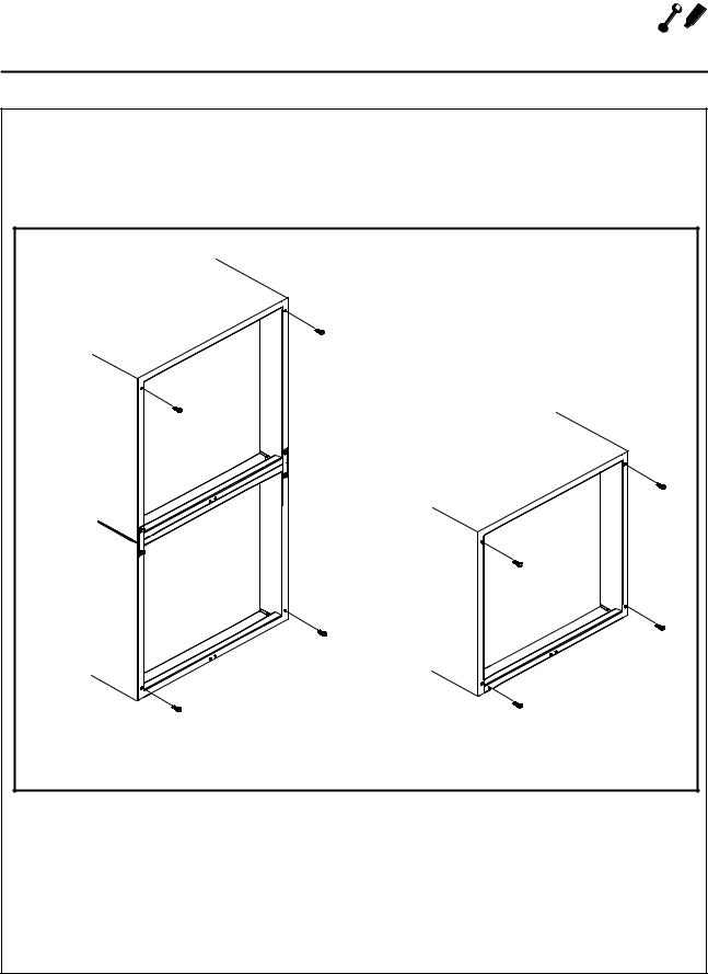
NSF BOLTS
These bolts are required by NSF to block any ex' posed hole on the back of an oven. This includes:
D any unit, single or stacked, without a back panel.
Dany holes in stacked units not used for mount' ing stacking brackets.
1.Locate the 5/16" bolts that were shipped with the oven.
2.Install the bolts as shown in Figure 2.
Double Stacked Units |
|
Units without back panels |
|
Figure 2
5
 Installation
Oven Assembly
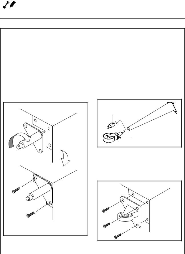
LEG ATTACHMENT
1.Push the oven onto a lift with the bottom of the oven down.
2.Align the threaded stud in each leg with the nut located inside each bottom corner of the oven frame. Turn the legs clockwise and tight' en to the nearest full turn.
3.Align the two leg plate holes in each leg with those in the oven bottom. Secure each leg us' ing two 1/2" bolts.
NOTE: If using casters see CASTER AS SEMBLY before proceeding.
4.Level the oven by screwing the adjustable leg feet in or out as necessary.
6" (15 cm) Legs Shown |
Figure 3
CASTER ASSEMBLY
NOTE: Install the locking casters on the front of the oven. Install the non locking casters on the back of the oven.
NOTE: Use a gas hose restraint on all units with casters. See page 12.
Casters for Single and Double Stacked Ovens:
1.Attach the legs as described.
2.Pry the adjustable feet out of the legs.
3.Insert one caster into each leg as shown. Tighten the large hex nut to secure the cast' ers.
Adjustable |
Leg Foot |
Caster Assembly |
Figure 4
Low Profile Casters for Double Stacked Ovens:
1.Align the three holes in each caster assembly plate with those in the oven bottom. Secure each caster using three 1/2" bolts.
Figure 5
6
Installation 
Oven Assembly
DOUBLE SECTION ASSEMBLY |
OVEN LEVELING |
1.Secure the short legs to the bottom sections as described.
2.Place the upper section in position on top of the lower oven.
3.Attach the stacking brackets using the re' maining 5/16" bolts shipped with the ovens.
4.Attach the flue connector.
WARNING!!
When stacking ovens be sure to remove the single oven flue boxes prior to attach ing three piece connector.
After assembly, the oven should be leveled and moved to the operating location.
1.The oven can be leveled by adjusting the feet or casters located on the bottom of each leg.
Flue |
Connector |
Figure 6
7
 Installation
Ventilation
On gas models the installation of a proper ventila' tion system cannot be over emphasized. This sys' tem removes unwanted vapors and products of combustion from the operating area.
This oven may be vented using either:
DA mechanically driven, canopy type, exhaust hood, or
DA direct flue arrangement.
U.S. and Canadian installations
Refer to your local ventilation codes. In the ab' sence of local codes, refer to the National ventila' tion code titled, •Standard for the Installation of Equipment for the Removal of Smoke and Grease Laden Vapors from Commercial Cooking Equip ment", NFPA 96 Latest Edition.
Australia and general export installations
Installation must conform with Local and National installation standards. Local installation codes and/or requirements may vary. If you have any questions regarding the proper installation and/or operation of your Blodgett oven, please contact your local distributor. If you do not have a local dis' tributor, please call the Blodgett Oven Company at 0011'802'860'3700.
WARNING:
Failure to properly vent the oven can be hazardous to the health of the operator and may result in operational problems, unsatisfactory baking and possible dam age to the equipment.
Damage sustained as a direct result of im proper ventilation will not be covered by the manufacturer's warranty.
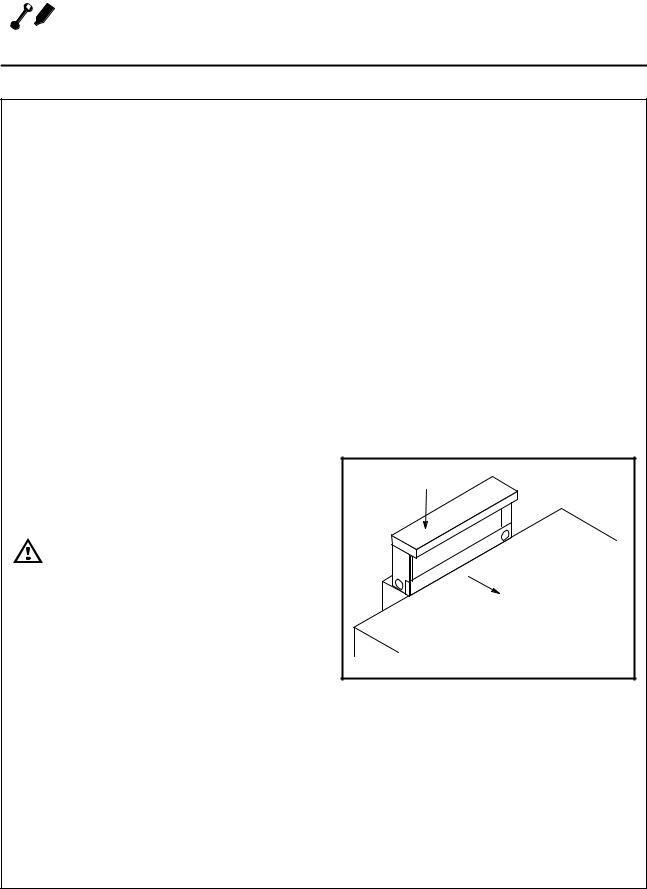
CANOPY TYPE EXHAUST HOOD
A mechanically driven, canopy type exhaust hood is the preferred method of ventilation.
The hood should be sized to completely cover the equipment plus an overhang of at least 6" (15 cm) on all sides not adjacent to a wall. The distance from the floor to the lower edge of the hood should not exceed 7' (2.1m).
The total makeup and exhaust air requirements for hood capacity should be approximately 30 CFM (.85 m3) for each oven section.
Installing the canopy hood draft diverter
Ovens ordered for hood venting are supplied with a draft diverter. Install the draft diverter as follows:
1.Place the diverter over the flue connector with the open area facing the front of the oven. See Figure 7.
2.Secure both ends with the sheet metal screws provided.
Draft Diverter |
Front of |
Oven |
Figure 7
8
Installation 
Ventilation
DIRECT FLUE ARRANGEMENT
When the installation of a mechanically driven ex' haust hood is impractical the oven may be vented by a direct flue arrangement.
 WARNING!!
It is essential that the direct flue be installed as follows. Incorrect installation will result in unsatisfactory baking and oven damage.
The flue must be class B or better with a diameter of 6" (15 cm). The height of the flue should rise 6'8 ft (2'2.5 m) above the roof of the building or any proximate structure. Never direct vent the oven into a hood. The flue should be capped with a UL Listed type vent cap to isolate the unit from exter' nal environmental conditions.
The direct vent cannot replace air consumed and vented by the oven. Provisions must be made to supply the room with sufficient make'up air. Total make'up air requirements for each oven section should be approximately 30 CFM (.85m3) per sec' tion. To increase the supply air entering the room, a ventilation expert should be consulted.
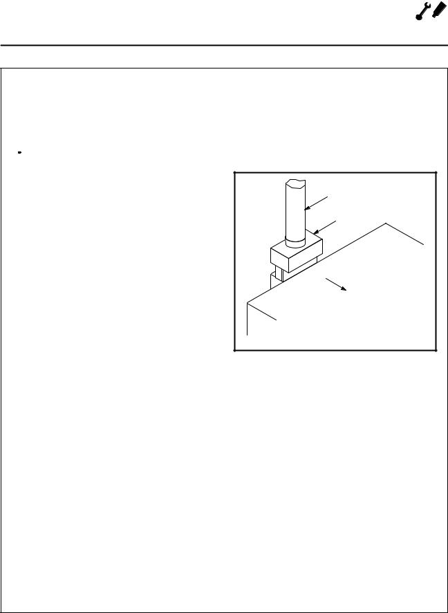
Installing the draft hood
Ovens ordered for direct venting are supplied with a draft hood. Install the draft hood as follows:
1.Place the draft hood over the flue connector. See Figure 8.
2.Secure both ends with the sheet metal screws provided.
Flue |
Draft Hood |
Front of |
Oven |
Figure 8
9

 Installation
Gas Connection
GAS PIPING
A properly sized gas supply system is essential for maximum oven performance. Piping should be sized to provide a supply of gas sufficient to meet the maximum demand of all appliances on the line without loss of pressure at the equipment.
Example:
NOTE: BTU values in the following example are for natural gas.
You purchase a Zephaire'G convection oven to add to your existing cook line.
1. Add the BTU rating of your current appliances.
Pitco Fryer |
120,000 |
BTU |
6 Burner Range |
60,000 |
BTU |
Deck Oven |
50,000 |
BTU |
Total |
230,000 |
BTU |
2.Add the BTU rating of the new oven to the to' tal.
Previous Total |
230,000 |
BTU |
Zephaire'240G |
50,000 |
BTU |
New Total |
280,000 |
BTU |
3.Measure the distance from the gas meter to the cook line. This is the pipe length. Let's say the pipe length is 40' (12.2 m) and the pipe size is 1" (2.54 cm).
4.Use the appropriate table to determine the to' tal capacity of your current gas piping.
The total capacity for this example is 320,000 BTU. Since the total required gas pressure, 280,000 BTU is less than 320,000 BTU, the current gas piping will not have to be in' creased.
NOTE: The BTU capacities given in the tables are for straight pipe lengths only. Any elbows or other fittings will decrease pipe capaci ties. Contact your local gas supplier if you have any questions.
Maximum Capacity of Iron Pipe in Cubic Feet
of Natural Gas Per Hour
(Pressure drop of 0.5 Inch W.C.)
Pipe |
|
Nominal Size, Inches |
|
||||
Length (ft) |
|
|
|
|
|
|
|
3/4" |
|
1" |
1 1/4" |
1 1/4" |
|
2" |
|
|
|
|
|
|
|
|
|
10 |
360 |
|
680 |
1400 |
2100 |
|
3950 |
|
|
|
|
|
|
|
|
20 |
250 |
|
465 |
950 |
1460 |
|
2750 |
|
|
|
|
|
|
|
|
30 |
200 |
|
375 |
770 |
1180 |
|
2200 |
|
|
|
|
|
|
|
|
40 |
170 |
|
320 |
660 |
990 |
|
1900 |
|
|
|
|
|
|
|
|
50 |
151 |
|
285 |
580 |
900 |
|
1680 |
|
|
|
|
|
|
|
|
60 |
138 |
|
260 |
530 |
810 |
|
1520 |
|
|
|
|
|
|
|
|
70 |
125 |
|
240 |
490 |
750 |
|
1400 |
|
|
|
|
|
|
|
|
80 |
118 |
|
220 |
460 |
690 |
|
1300 |
|
|
|
|
|
|
|
|
90 |
110 |
|
205 |
430 |
650 |
|
1220 |
|
|
|
|
|
|
|
|
100 |
103 |
|
195 |
400 |
620 |
|
1150 |
|
|
|
|
|
|
|
|
From the National Fuel Gas Code Part 10 Table 10 2
Maximum Capacity of Pipe in Thousands of BTU/hr of Undiluted L.P. Gas at 11" W.C.
(Pressure drop of 0.5 Inch W.C.)
Pipe Length |
Outside Diameter, Inches |
|||
(ft) |
|
|
|
|
3/4" |
1" |
1 1/2" |
||
|
||||
|
|
|
|
|
10 |
608 |
1146 |
3525 |
|
|
|
|
|
|
20 |
418 |
788 |
2423 |
|
|
|
|
|
|
30 |
336 |
632 |
1946 |
|
|
|
|
|
|
40 |
287 |
541 |
1665 |
|
|
|
|
|
|
50 |
255 |
480 |
1476 |
|
|
|
|
|
|
60 |
231 |
435 |
1337 |
|
|
|
|
|
|
70 |
215 |
404 |
1241 |
|
|
|
|
|
|
80 |
198 |
372 |
1144 |
|
|
|
|
|
|
90 |
187 |
351 |
1079 |
|
|
|
|
|
|
100 |
175 |
330 |
1014 |
|
|
|
|
|
|
From the National Fuel Gas Code Part 10 Table 10 15
10
 Loading...