


HELSINKI RTM 127
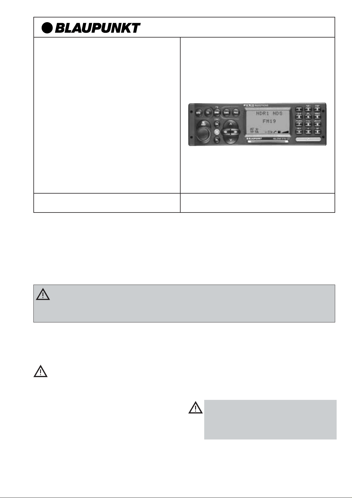
Helsinki RTM 127
7 647 982 010
Einbauanleitung (D) Seite 1
Fitting instructions (GB) page 8
Instructions de montage (F) page 11
Istruzioni di montaggio (I) pagina 14
Inbouwinstrukties (NL) pagina 17
Monteringsanvisninsida (S) sida 20
Instrucciones de montaje (E) página 23
Instruções de montagem (P) página 26
8 622 401 055/03.98St.
Sicherheitshinweise
Das Radiophone sollte nur vom Fachpersonal in Ihrem Kraftfahrzeug installiert und gewartet werden. Fehlerhafte
Installation oder Wartung kann gefährlich sein und zum Erlöschen der Garantie führen.
Wird das Fahrzeug nicht ausreichend gegen Hochfrequenz-Signale geschützt, können bei elektronischen Kraftstoffeinspritz-Systemen, elektronischen ABS- Systemen, elektronischen Fahrgeschwindigkeitsreglern oder anderen elektronischen Systemen Fehlfunktionen auftreten.
Vor Einbau Ihres Autoradios die Einbau- und Anschlußvorschriften lesen.
Für die Dauer der Montage und des Anschlusses
ist der Minuspol der Batterie abzuklemmen.
Hierbei sind die Sicherheitshinweise des Kfz-Herstellers (Airbag, Alarmanlagen, Bordcomputer,
Wegfahrsperren) zu beachten.
Beim Bohren von Löchern darauf achten, daß keine Fahrzeugteile (Batterie, Kabel, Sicherungskasten) beschädigt werden.
Der Querschnitt des Plus und Minuskabels darf
1,5 mm
ner Sicherung, 10 A flink, abgesichert.
2
nicht unterschreiten. Das Gerät ist mit ei-
Das Seitenteil des Autoradios wird im Betrieb sehr
heiß. Es ist darauf zu achten, daß keine Kabel am
Gehäuse anliegen.
In einigen Fahrzeugen liegt ein 20 poliger Stecker
im Einbauschacht. Dieser Stecker darf nicht am
Autoradio angeschlossen werden.
In allen Fahrzeugen darf der fahrzeugseitige 8 polige
+/- ISO-Stecker nicht direkt an Ihren Helsinki angeschlossen werden.
Immer Adapterkabel benutzen!
Achtung! Bei Falschanschluß erlöscht der Garantieanspruch!
- 1 -
Anschlußvorbereitung
Der folgende Abschnitt gibt Ihnen eine kleine
Einbauübersicht.
Welche Autoradiokomponenten befinden sich in Ihrem
Fahrzeug?
Autoradio, Lautsprecher mit Verstärker (aktiv), oder ohne Verstärker (passiv), Antenne mit oder ohne Verstärker, Motorantenne, Scheibenantenne.
Mit welchen Steckverbindungen ist ein vorhandenes Radio adaptiert?
Sind es ISO-Norm Anschlüsse (würden mechanisch an Ihren
Helsinki passen) oder Kfz.-spezifische?
Wie groß ist der Querschnitt von eventuell vorhandenen Kabeln?
Fahrzeuge ohne Autoradios
Liegen bereits Lautsprecher und Stromkabel im Fahrzeug? Sind
es ISO-Norm Anschlüsse oder Kfz.-spezifische?
Wie groß ist der Querschnitt von eventuell vorhandenen Kabeln?
Wie sieht ein ISO-Norm Stecker aus?
Schauen Sie sich bitte die mitgelieferten Anschlußkabel an.
Beide sind mit ISO-Norm Steckern versehen. Am Plus/MinusAnschlußkabel sind die beiden roten Drähte und der braune
Draht mit 1,5 mm
gelb/grüne Draht haben einen Querschnitt von 1mm
ISO-Norm Stecker können je nach Kfz.-Hersteller
unterschiedliche Anschlußbelegungen haben!
Für die Dauer der Montage und des Anschlusses
ist der Minuspol der Batterie abzuklemmen.
Hierbei sind die Sicherheitshinweise des Kfz-Herstellers (Airbag, Alarmanlagen, Bordcomputer,
Wegfahrsperren) zu beachten.
2
Querschnitt versehen. Der orange und der-
2
.
• Strom-Anschluß
Anschluß an Fahrzeugseitige ISO-Norm Stekker.
In allen Fahrzeugen darf der fahrzeugseitige 8 polige
+/- ISO-Stecker nicht direkt an Ihren Helsinki angeschlossen werden. Immer Adapterkabel benutzen.
Bei Falschanschluß erlöscht der Garantieanspruch!
Zur Vermeidung von elektrischen Fehlanschlüssen bei fahrzeug-seitigen ISO-Steckern ist das
bel
(Best.- Nr. 7 607 621 126) für den Dauerplus, Minus, Plus
über Zündung, Beleuchtungsanschluß und Plus 12V Schaltausgang für externe Komponenten z.B.: Motorantenne zu verwenden.
Zur Zeit können folgende Fahrzeuge mit ISO-Norm Anschlüssen mit dem
werden
des, Peugeot, Porsche, Renault, Skoda.
Achtung! Für andere Fahrzeuge mit ISO-Norm Anschlüssen ist
das Kfz.- spezifische Adapterkabel zu verwenden.
Es muß sichergestellt sein, daß der Radioanschluß im Auto
bereits werkseitig mit einer 10 A Sicherung abgesichert ist .
:
Alfa Romeo, Citroen, Fiat, Honda, Lancia, Merce-
Universal-ISO-Adapterkabel
Strom-Anschluß an Kfz.-spezifische Stecker.
Ist Ihr Radioanschluß im Auto bereits werkseitig mit einer 10A
Sicherung abgesichert (siehe Bedienungsanleitung oder Sicherungskasten Ihres Kfz.), so benötigen Sie noch das Kfz.-
spezifische Adapterkabel und das Universal-Spannungsversorgungskabel welche im Fachhandel erhältlich sind (sie-
he Fig. 6, Seite 5).
Bei weniger als 10A Absicherung, muß wie unter "Anschluß in
Fahrzeugen ohne jegliche Vorrüstung" beschrieben eingebaut
werden.
Universal-ISO-Adapterka-
adaptiert
Anschluß in Fahrzeugen ohne jegliche
Vorrüstung.
Bei Fahrzeugen ohne Autoradio- Vorrüstung oder zu geringen
Plus-Minus Kabelquerschnitten (< 1,5 mm
ISO +/- Anschlußkabel
gelb/grünen und zwei roten Kabeln) mit dem
nungsversorgungskabe
Nr. 7 607 884 093) zu verbauen (siehe Fig. 4, Seite 4).
(zu erkennen am braunen, orangen,
l (im Fachhandel erhältlich; Best.-
2
) ist das beiliegende
Universal-Span-
• Lautsprecheranschluß
Lautsprecheranschluß an Fahrzeugseitige
ISO-Norm Stecker.
Bei dieser Anschlußart muß geklärt werden ob sie eine passive
oder aktive Lautsprechervorrüstung haben. Passiv entspricht;
Lautsprecher ohne eigenen Verstärker. Aktiv mit Verstärker.
Diese Info können Sie über Ihren Kfz.- oder Fachhändler beziehen.
Bei einer passiven Vorrüstung (mit 4 Ohm Lautsprecher)
können Sie den im Kfz. befindlichen ISO- Stecker adaptieren.Bei
Bedarf mit ISO-Kabel (7 607 647 093) verlängern.
Für eine aktiv Vorrüstung können Sie über Ihren Fachhändler
für bestimmte Fahrzeuge entsprechende Adapterkabel beziehen.
Lautsprecheranschluß in Fahrzeugen ohne
jegliche Vorrüstung.
Bei nachträglich eingebauten Lautsprechern verwenden Sie das
beigelegte
dem ISO-Lautsprecherkabel und den Lautsprechern können Sie
mit Lüsterklemmen (nicht im Lieferumfang enthalten) herstellen
(siehe Fig. 7, Seite 5).
ISO-Lautsprecherkabel
. DieVerbindung zwischen
• Antenneneinbau
Hier gibt es eine große Auswahl von Antennentypen. Interessant wären z.B. Kombiantennen. Ihr Bosch-Händler wird
Sie gern beraten.
Radioantenne
Bei neueren vorgerüsteten Fahrzeugen z.B.: VW, Seat, Audi
wird die Versorgungsspannung für die Antenne über das Antennenkabel zugeführt.(Siehe Bedienungsanleitung vom Kfz.) Soll
das Erstausrüstungsradio gegen ein handelsübliches Radio
ausgetauscht werden, so ist eine Antenneneinspeiseweiche
(Best.-Nr. 7 691 290 202) von Ihrem Fachhändler zu beziehen.
Antenneneinbau und Anschluß siehe Antenneneinbauanleitung.
Je nach vorhandenen Antennentyp muß evt. beiliegender Antennenadapter mit Halter verwendet werden (siehe Fig. 3a,
Seite 3).
Telefonantenne
Nach Einbau der Antenne den Anschluß am Radio handfest
anziehen, und noch eine
ziehen.
Hinweis: Die Telefonantenne muß mit mindestens 1m Abstand zur Radioantenne verbaut werden. Die Telefonantennenleitung darf nicht in die Nähe der Lautsprecherleitungen
verlegt werden.
1
/4 Umdrehung mit einer Zange nach-
• Autoradioeinbau
Das Autoradio wird in den vom Fahrzeughersteller vorgesehenen Autoradioausschnitt eingebaut. Autoradioausschnitt freilegen (Ablagefach oder Blindblende ausclipsen) oder Autoradioausschnitt auf 182 x 53 mm ausarbeiten.
Für Fahrzeuge mit abweichender Einbausituation liefert Blaupunkt für die gängigsten Fahrzeuge fahrzeugspezifische Einbausätze für 50 mm Geräte. Prüfen Sie daher, welche Einbausituation im Fahrzeug vorliegt, und verwenden Sie zum Einbau
gegebenenfalls einen fahrzeugspezifischen Einbausatz.
- 2 -
8 622 401 055
Fahrzeugseitiger Halterahmen oder Fernbedie-
PIN 2
nungen
Bei Fahrzeugen, die fahrzeugseitig mit einem Halterahmen
ausgerüstet sind (z. Z. Opel), muß der fahrzeugseitige Halterahmen ausgebaut werden. Fahrzeugseitige Lenkradfernbedienungen können bei einigen Fahrzeugen mit einem entsprechenden Interface adaptiert werden. Bitte beim Fachhänder informieren.
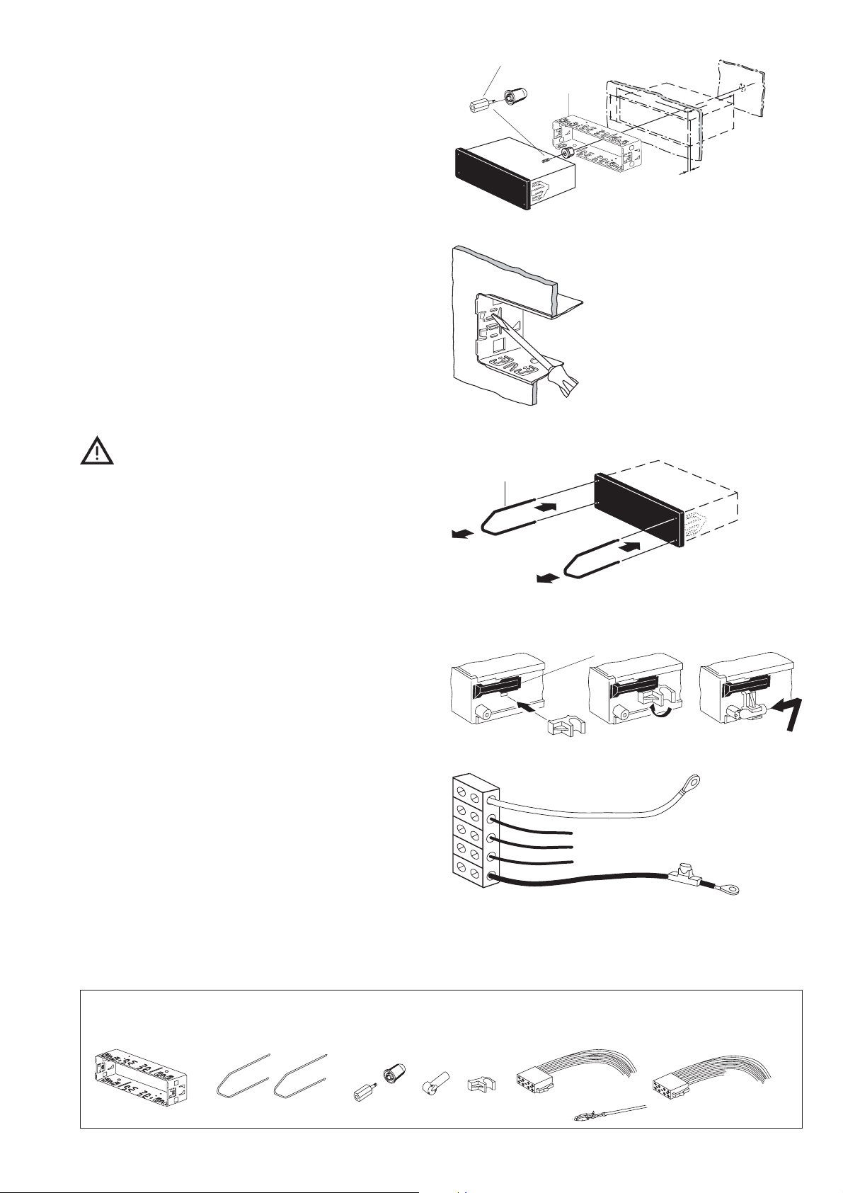
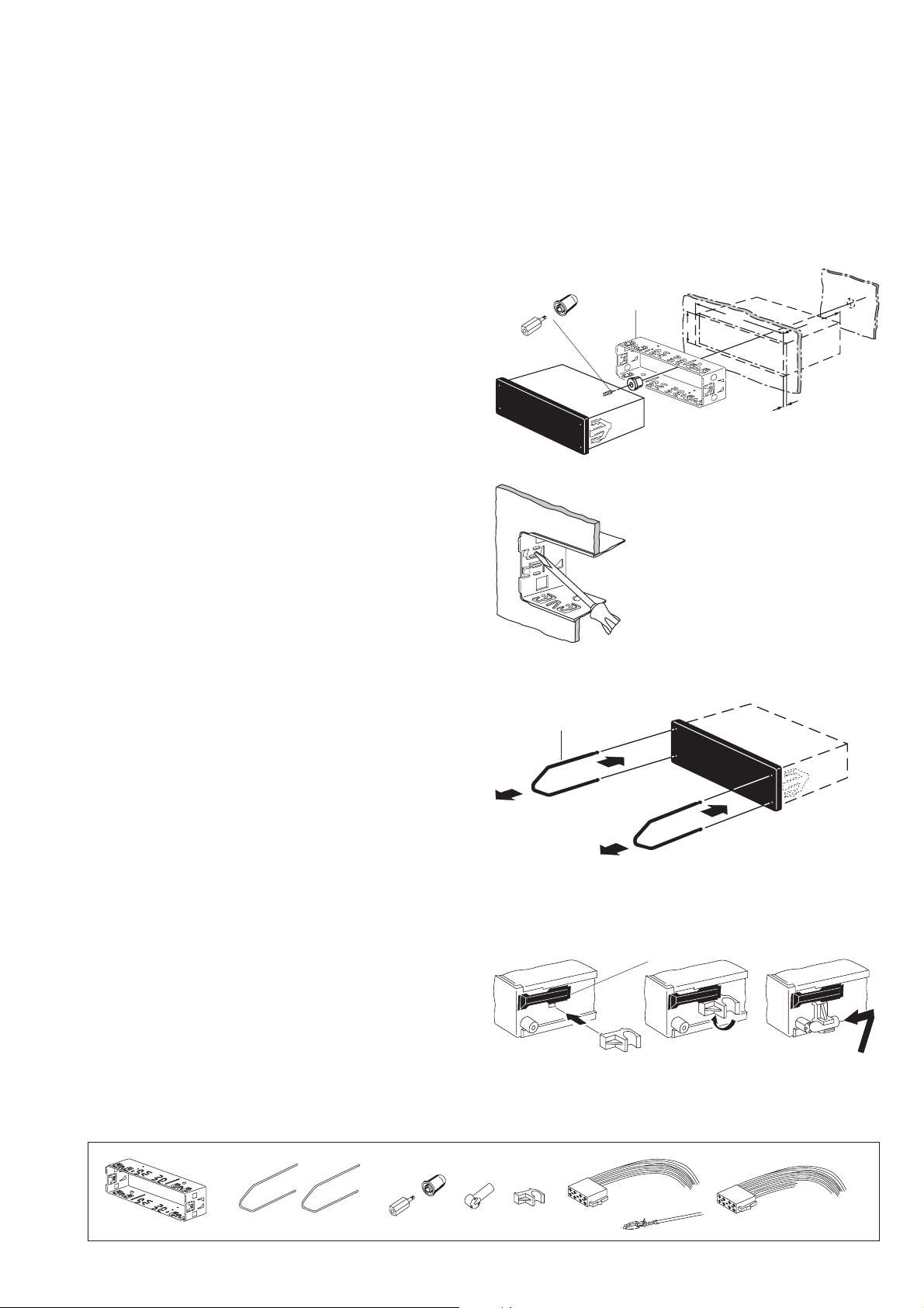
Einbau der Halterung
Die zum Lieferumfang dieses Autoradios gehörende Halterung
ermöglicht den Einbau in Fahrzeugen mit DIN- Autoradioausschnitt von 182 x 53 mm, 165 mm Einbauraum und einer Instrumententafeldicke im Bereich der Befestigungslaschen von 1 20 mm, siehe Fig. 1.
Halterung in den Ausschnitt schieben und prüfen, welche Befestigungslaschen der Halterung mit einem Schraubendreher
umgebogen werden können (siehe Fig. 1 u. 2).
Hinweis: Möglichst alle Befestigunglaschen umbiegen.
Autoradioeinbau
Alle Stecker so weit in die Kammern einschieben, bis die
seitlichen Rastnasen einrasten.Das Autoradio von vorn in die
Halterung einsetzen. Durch sanften Druck auf beide Rahmenenden einschieben, bis die seitlichen Rastfedern rechts und links
arretieren (deutliches Knacken hörbar) (siehe Fig. 3).
Beim Einschub nicht auf Display, Knöpfe oder Schalter drücken!
Autoradioausbau
Bügel links und rechts in die vorhandenen Löcher der Blende
stecken und so weit eindrücken, bis deutliches Knacken zu
hören ist (seitliche Federn entriegelt).
Gerät an den beiden Bügeln vorsichtig herausziehen. Jetzt
können die Anschlußkabel durch seitlichen Druck auf die jeweilige Rastnase herausgezogen werden (siehe Fig. 3).
Hinweis: Eingerastete Bügel können nur nach Herausziehen
des Gerätes entfernt werden.
Der Führungsbolzen wird mit oder ohne Distanzstück auf das
Schraubgewinde der Geräterückwand gesteckt.
8 601 310 742
182
53
Fig.1
Fig.2
8 601 910 002
1
2
1
2
Fig.3
165
1-20
Telefonantenne
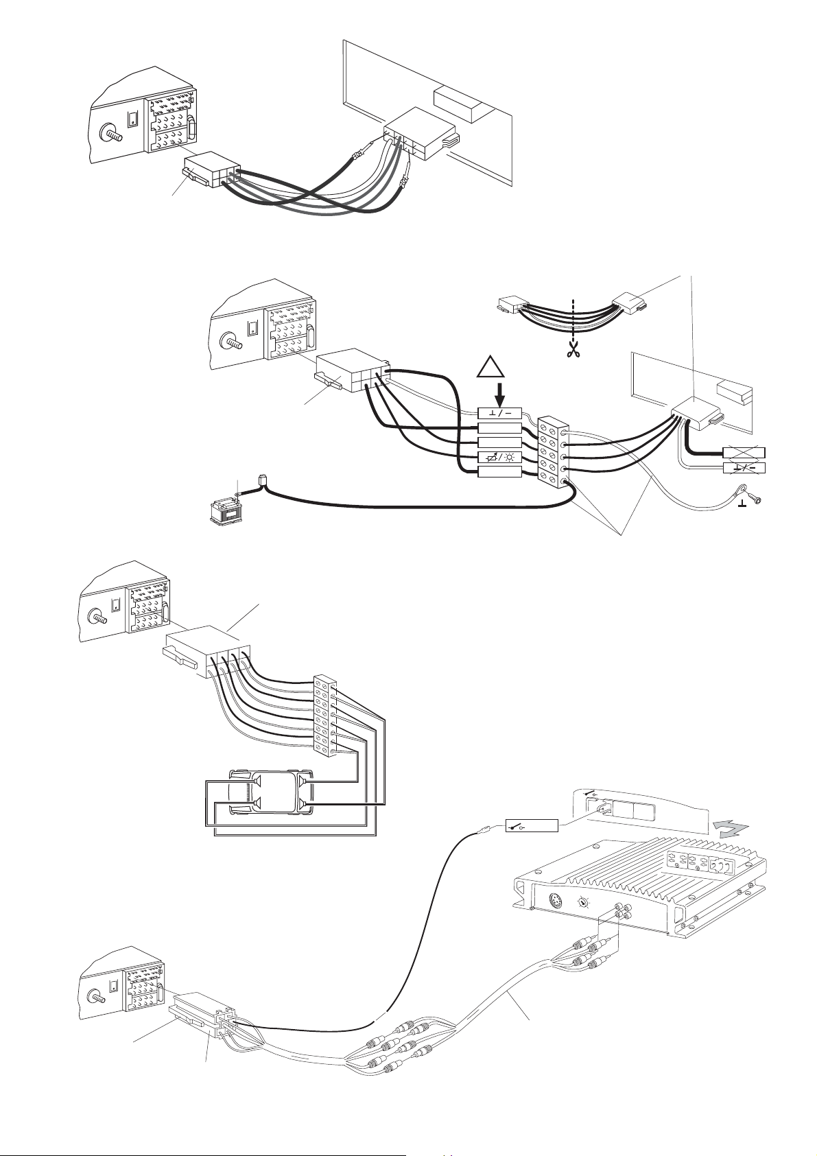
Anschlußzeichnungen
Anschluß in Fahrzeugen ohne jegliche Vorrüstung .......Fig. 4
Strom-Anschluß an Fahrzeugseitige ISO-Norm SteckerFig. 5
Strom-Anschluß an Kfz.-spezifische Stecker. ................Fig. 6
Lautsprecheranschluß 4 AL (4 Ω/35 W)........................Fig. 7
LF = links vorn, RF = rechts vorn,
Fig.3a
LR = links hinten, RR = rechts hinten.
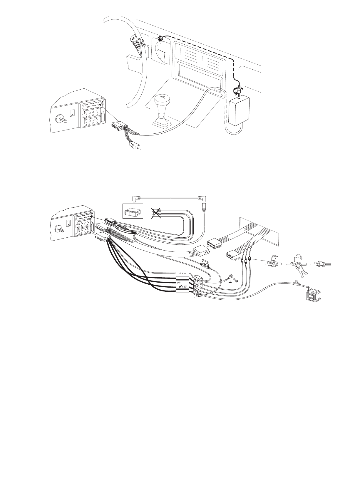
Equalizer oder Amplifieranschluß (CINCH)....................Fig. 8
Anschluß mit Freisprechmikrofon..................................Fig. 9
Anschluß mit Telefonhörer (Handset 7 607 570 512) ..Fig. 10
Anschluß CD- Player CDC- A06/072 ............................Fig. 11
Anschluß IR- Fernbedienung RCT 07...........................Fig. 12
Anschluß CD-Player CDC-A05/071 ..............................Fig. 13
Anschluß CD-Player CDC-F05 .....................................Fig. 14
Universal-Spannungsversorgungskabel,Universal power
cable,Câble d‘alimentation électrique universel, Cavo di
adattamento universale, Universele voedingskabel, Universalspänningskabeln,cable de alimentación universal , comércio
especializado Nr. 7 607 884 093
15A
Mitgelieferte Montage- und Anschlußteile - Supplied Mounting Hardware - Materiel de montage fourni - Ferretería de
montaje suministrada - Componenti di fissaggio comprese nella fornitura - Meegeleverde montagematerialen Medföljande monteringsdetaljer - Elementos de fixação fornecidos.
Radioantenne
- 3 -
8 622 401 055
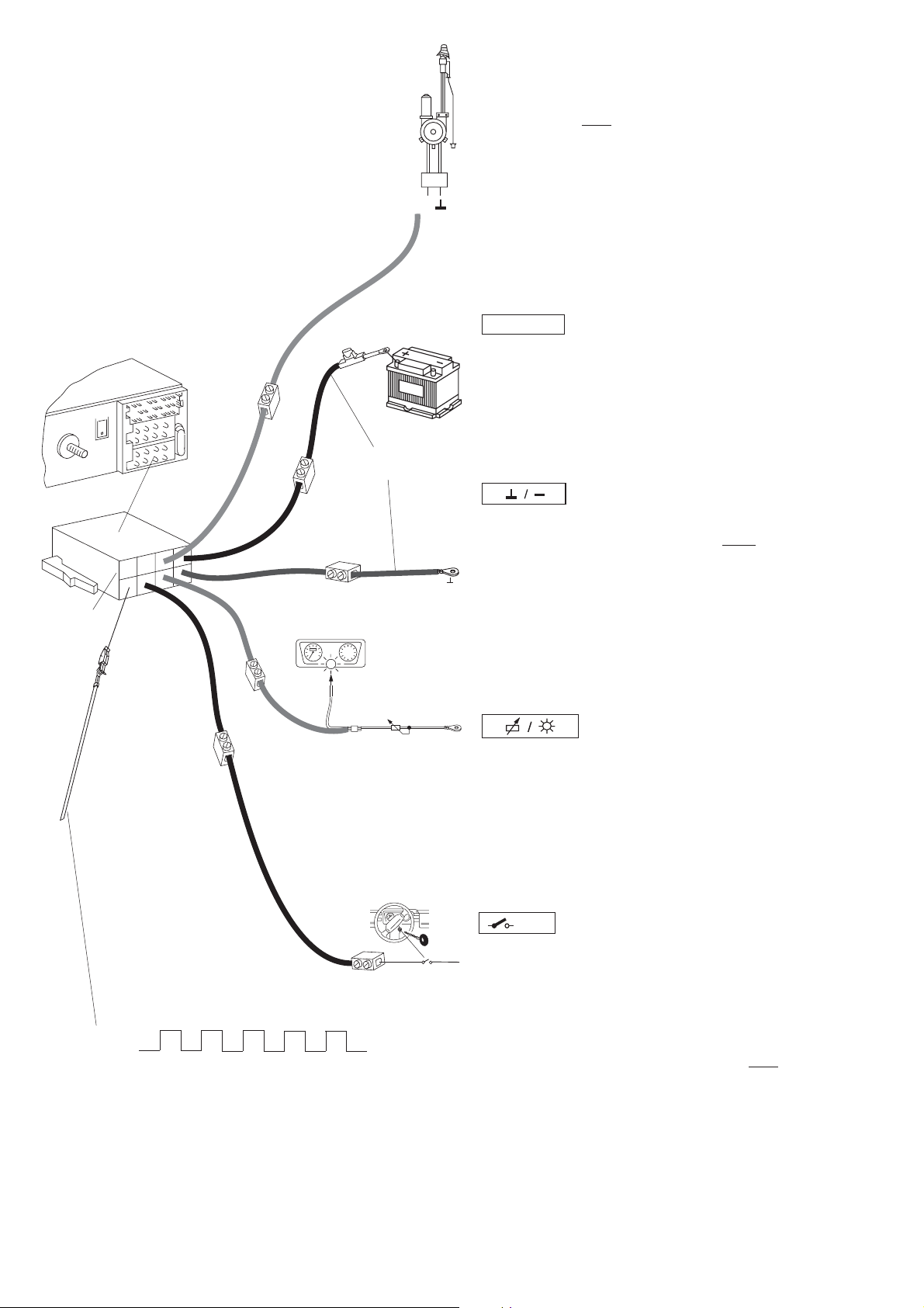
8 604 390 045
10A
gelb/grün
braun
orange
rot
Relais
+12V
12V
UniversalSpannungsversorgungskabel
7 607 884 093
Steuerkabel (Power Antenna +)
Das Steuerkabel ist der geschaltete Plusausgang für
externe Komponenten z.B.: Motorantenne,
(maximale Belastung < 150 mA).
Das Steuerkabel
nicht an Klemme 15 (Plus geschaltet) oder
Klemme 30 (Dauerplus) anschließen.
per. +12V
Dauerplusanschluß (Kl.30 Batterie + 12 V)
Pluskabel (rot) mit starkem Querschnitt (min.1,5 mm2) zur
Batterie verlegen (Kabel nicht unmittelbar an Kabelbäumen
verlegen). Sicherungshalter zur Absicherung des Plus-
kabels anschließen und am Pluspol der Batterie anklemmen.
Masseanschluß (Ground)
2
Massekabel (min. Querschnitt 1,5 mm
) nicht am Minuspol
der Batterie anklemmen.
Massekabel zu einem geeigneten Massepunkt verlegen
(Karosserieschraube, Karosserieblech). Massekabel abisolieren und Krallenkabelschuh anschlagen (ggf. nachlöten). Kontaktfläche des Massepunktes metallisch blank
kratzen und mit Graphitfett einfetten (wichtig für gute Masseverbindung). Massekabel anschrauben.
rot
Externer Alarm
1
345
2
< 1s
nur bei Zündung aus und aktivierten
externen Alarm
Anschluß an PIN 2 nur über ein Relais
(maximale Belastung < 100 mA). Dauer = 5 Klingeltöne
Kl.15 +12V
Beleuchtungsanschluß (Illumination) Beleuchtungsanschluß für Fahrzeuge mit regelbarer Instrumentenbeleuchtung (plusgeregelt). Bei nicht vorgerüsteten Fahrzeugen den Anschluß beim Kfz.-Händler erfragen.
+12V
Plusanschluß (über Zündung geschaltet)
Wird das Pluskabel am Sicherungshalter (Kl.15) hinter
der Sicherung angeschlossen, so ist das Ein- und Ausschalten des Autoradios über Zündung möglich. Außerdem schaltet das Gerät zum Schutz der Batterie automatisch nach einer Stunde aus.
" Zündtimer 00 " .Die Stunden-Logik wird
nicht aktiviert,
wenn Dauerplus (Kl.30) angeschlossen wird.
Fig.4
- 4 -
8 622 401 055
10A
7 607 621 126
Fig. 5
Kfz.-spezifisches Adapterkabel, adapterwiring
adaptateur, cavo di adattamento
adapterkabel, adapterkabelkabe
el cable adaptador, cabo de adaptação
10A
!
Fig. 4
8 604 390 045
Kl.15
12V
Antenne
15A
V
2
1
per.+12V
per.+12V
Universal-Spannungsversorgungskabel, connection wiring câble de
raccordement, câble de raccordement, aansluitkabel anslutningskabel, cable
de conexión, cabo de ligação
8 604 390 087
10A
LR
LF
RF
RR
+
-
+
-
+
-
+
-
RR
RF
LF
LR
(7 607 884 093)
Fig. 6
+12V
+12V
Fig. 7
gelb/yello/jaune
giallo/geel/gul
10A
7 607 893 093
0,3 m
- 5 -
Fig. 8
7 607 886 093
5 m
8 622 401 055
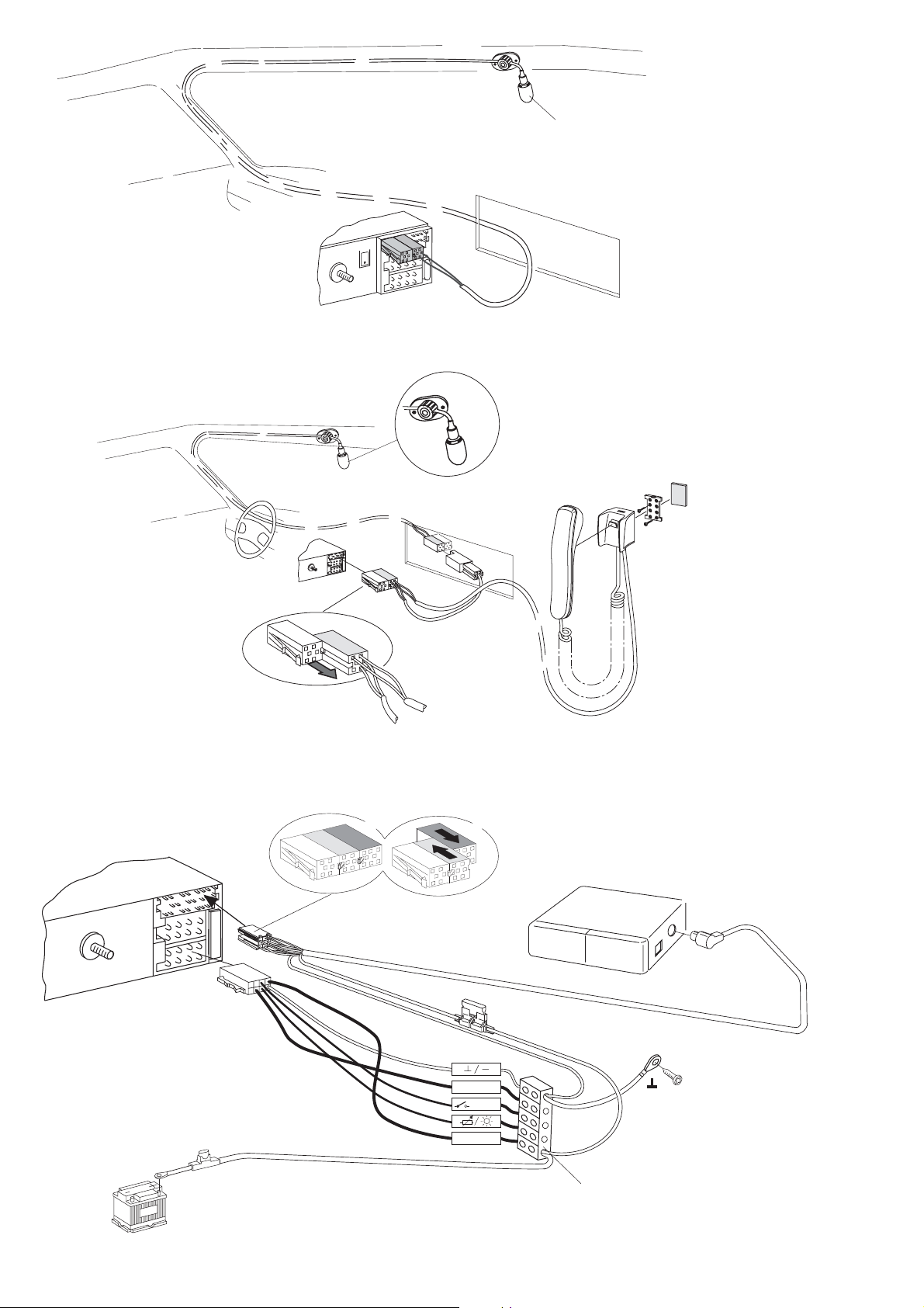
Fig. 9
Einbau in Spiegelnähe,
positionning near the interior miror,
Position près de la miroire intèrieure,
Monteras i närheten av spegeln.
Instalación cerca del espejo.
10A
10
10
Fig. 10
Fig. 11
3
2
10
10
br
1
3A
+12V/ kl15
+12V
CDC A06
A072
8 619 000 200 5m
rt
12V
per.+12V
15A
7 607 884 093
8 622 401 055
- 6 -
10A
Fig. 12
Fig. 13
CDC
CDC A05
10A
Power/Bus 5m
A071
7 607 889 093
7 607 647 093
+12V
+12V
per.+12V
1
15A
2
3
12V
7 607 884 093
Fig. 14
- 7 -
8 622 401 055Änderungen vorbehalten!

GB
Fittings instructions
Have the Radiphone installed in your vehicle and serviced by a trained service technician only. Faulty installation or
servicing can be dangerous and will result in the expiry of your guarantee.
If the vehicle is not adequately shielded against radio frequency signals, electronic injector systems, electronic ABS
systems, electronic cruise control systems or other electronic equipment may experience malfunctions.
Safety notes
Before starting to mount your car radio, read the mounting and
connection instructions carefully.
Disconnect the vehicle battery’s negative terminal before making
connections.
Be sure to observe the safety notes of the automobile manufacturer
(airbags, alarm systems, on-board computers, immobilisers).
Before drilling holes, look to see what is on the other side - making
holes into the battery, wiring looms or fuse box is not recommended!
The positive lead used must have a cross-section of at least 1.5
mm2. The set is protected by a quick-acting 10 A fuse.
During operation of the unit, the set’s side wall may heat up
considerably.
Be sure to keep all wires away from hot parts of the housing.
In some vehicles you will find a 20-pin connector pre-fitted in the
dashboard’s installation space. This connector must not be used
for connecting the car radio!
You must not connect your Helsinki car radio to an existing
8-pin +/- ISO connector in your car. Always use the adapter
cable. Our warranty shall be vain if the connection is made
inadequately.
Preparing for the installation
The following section gives you a brief installation overview.
What car radio components are installed in your car?
Car radio, loudspeakers with amplifier (active) or without amplifier
(passive), antenna with or without amplifier, power antenna, window
antenna.
What adapters are used for the existing car radio?
Are there standard ISO connectors (which are compatible with your
Helsinki car radio) or car specific adapters?
What cross-section do the existing cables have?
Vehicles without car radio
Are loudspeakers and power cables installed in your car? Are standard
ISO connectors or car-specific adapters used?
What cross-section do the existing cables have?
What does an standard ISO connector look like?
Take a look at the cables included in the delivery. Both cables are
equipped with standard ISO connectors. The two red wires and the
brown wire of the positive and negative cable have a cross-section of 1.5
mm2. The orange and the yellow/green wire have a cross-section of 1
mm2.
The pinning of standard ISO connectors may differ according to auto manufacturer.
While installing and mounting this equipment, you must
disconnect the negative terminal of the battery.
You must also comply with all safety instructions given by
the auto manufacturer (airbag, alarm system, board computer, vehicle immobilizer).
Helsinki RTM 127
• Connecting the power supply
Connection to standard ISO adapter installed in
your car.
You must not connect your Helsinki car radio to an existing
8-pin +/- ISO connector in your car. Always use the adapter
cable. Our warranty shall be vain if the connection is made
inadequately.
To prevent inadequate electrical connection in vehicles equipped with
ISO connectors, use the universal ISO adapter cable (P/N 7 607 621 126)
for constant power connection, negative connection, the positive connection via the ignition, illumination and +12V switching output for
external components such as a power antenna.
At present, the following vehicles with standard ISO connectors
can be adapted using the universal ISO adapter cable: Alfa Romeo,
Citroen, Fiat, Honda, Lancia, Mercedes, Peugeot, Porsche, Renault,
Skoda.
Attention! For all other car models with standard ISO connector use the
car-specific adapter cable. Make sure that the existing car radio terminal
in the your car is protected by a 10 A fuse.
Power supply to vehicle-specific connectors
If the existing car radio terminal in your car is protected by a 10 A fuse (see
operating instructins or fuse box in your car), you only need to have the
car-specific adapter cable which is available at your dealer (see Fig.
6,page 5).
If the fuse value is less than 10 A, follow the steps described under
„Connection in vehicles without car radio wiring“.
Connection in vehicles without car radio wiring
If your car is not equipped with any car radio wiring or if the cross-section
of the existing positive/negative wires is insufficient (< 1.5 mm2), install
the enclosed ISO +/- cable (one brown, orange, yellow/green wire and
two red wires) together with the universal power supply cable (available
at your specialist dealer; P/N 7 607 884 093); see Fig. 4 (page 10).
• Connecting the loudspeakers
Loudspeaker connection to the standard ISO adapter in your car
For this type of connection, first check whether you have passive or active
loudspeakers installed in your car. Active loudspeakers have an integrated amplifier, passive loudspeakers do not have an amplifier. For more
information contact your car dealer or audio dealer.
If your car is equipped with passive loudspeakers (4 ohms) you can adapt
the ISO connector installed in your car. Use ISO cable (7 607 647 093)
to prolong your wiring. If active loudspeakers are installed in your car, you
can order the necessary adapter cable for various vehicles from your
specialist dealer.
Loudspeaker connection in vehicles without
loudspeaker wiring
For subsequently installed loudspeakers use the ISO loudspeaker cable
included in the delivery. Use cable connectors to link the ISO loudspeaker cable to the loudspeakers (not included in the delivery); see Fig. 7
(page 5).
8 622 401 055
- 8 -
• Installing the antenna
PIN 2
8 601 910 002
2
2
1
1
A wide range of different antennas is available in the market.
Combination antennas, for example, are an
For more information please contact your Bosch dealer.
interesting solution.
Radio antenna
In new vehicles with antenna prefitting, e.g. VW, Seat, Audi, the power
is supplied to the antenna via the antenna cable (see user manual of your
car). If you wish to replace the original equipment for a conventional car
radio, you need to purchase an antenna duplexer (P/N 7 691 290 202)
from your specialist dealer. Information on how to install and connect
your antenna is provided in the antenna installation instructions. According
to the antenna type you wish to install, it may be necessary to use the
antenna adapter with holder included in the delivery (see Fig. 3a).
Telephone antenna
The Telephone ariel (GSM) shold be installed to 1m- distance from radio
one. After you have installed the antenna, tighten the connection at your
car radio by hand und add another 1/4 rotation using pliers.
Note: Make sure the telephone wires are not routed close to the
loudspeaker wiring.
• Installing the car radio
Install your car radio into the car radio compartment of your car.Uncover
the radio compartment (remove the shelf or the dummy panel) or cut the
car radio slot to a size of 182 x 53 mm. For the most common cars with
deviating installation places Blaupunkt offers specific 50-mm car radio
installation kits. Therefore, please check the car radio installation place
in your car. If required, use one of our car-specific installation kits.
Car radio sleeve or remote control installed in your
car
If your vehicle is equipped with a specific car radio mounting sleeve (e.g.
Opel), it is necessary to remove the original sleeve. Steering wheel
remote controls installed in some vehicles can be adapted by means of
an interface. Contact your specialist dealer for more information.
Installing the mounting sleeve
The mounting sleeve included with this car radio is designed for installation in vehicles with standard DIN installation compartment measuring
182 x 53 mm, 165 mm installation depth and a dashboard thickness of
1 to 20 mm in the area of the tab fasteners (see Fig. 1).Insert the car radio
into the sleeve and check which tabs on the sleeve can be bent with the
help of a screwdriver (see Fig. 1 and 2).
Note: Bend as many taps as possible.
Installing the car radio
Insert all connectors into the chambers until the side catches engage.
Place the car radio in the front of the sleeve and push it in gently on both
ends of the sleeve until the left and right side springs snap into place (you
will hear an audible click), see Fig. 3.
Advantage! Do not push on the display, keys or switches!
Removing the car radio
Insert the handles into the holes in the panel on the left and right side of
the radio and push them in until you hear an audible click (the side springs
unlock). Gently pull the unit out using both handles (see Fig. 3).
Note: Handles which have snapped into place can only be removed
after you have pulled the radio out of the compartment.
Connecting diagrams
Vehicles without car radio prefitting (page 10) .......................... Fig. 4
Power supply to standard ISO connectors (page 5) ................. Fig. 5
Power supply to car-specific connectors (page 5) .................... Fig. 6
Loudspeaker connection 4x 4Ω/35 watts (page 5) ................... Fig. 7
Equaliser or amplifier connection (page 5) ............................... Fig. 8
LF = left front, RF = right front
LR = left rear, RR = right rear
Handsfree microphone connection (page 6) ............................. Fig. 9
Handset connection (7 607 570 512) (page 6) ......................... Fig. 10
CD player connection (CDC A06/072) (page 6)........................ Fig. 11
IR remote control connection (RCT 07) (page 7) ...................... Fig. 12
CD player connection (CDC-A05/071) (page 7) ....................... Fig. 13
CD player connection (CDC-F05) (page 7)............................... Fig. 14
Fix the guide pin with or without spacer
on the stud at the car radio rear side.
8 601 310 742
182
53
165
1-20
Fig.2
Fig.3
Telephon antenna
Radio antenna
Fig.3a
Mounting and connection hardware included in the delivery
- 9 -
8 622 401 055
 Loading...