


DSP1100P
Table of contents
 Loading...
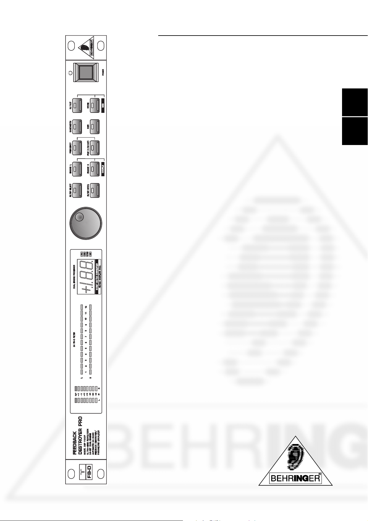
EUser´s Manual
Bedienungsanleitung
PRO DSP1100P
®
D
Version 1.0 October 1998
FEEDBACKDESTROYER
www.behringer.de
1

EG-Declaration of Conformity
acc. to the Directives
89/336/EWG and 73/23/EWG
We, BEHRINGER INTERNATIONAL GmbH
Hanns-Martin-Schleyer-Straße 4
D - 47877 Willich
Name and address of the manufacturer or the introducer of the product on the market who is established in the EC
herewith take the sole responsibility to confirm that the product:
FEEDBACKDESTROYERPRO DSP1100P
Type designation and, if applicable, Article-N
o
Spezielle Studiotechnik GmbH
which refers to this declaration, is in accordance with the following standards or standardized documents:
x EN 60065 x EN 61000-3-2
x EN 55020 x EN 61000-3-3
x EN 55013 x EN 55022
The following operation conditions and installation arrangements have to be presumed:
acc. to Operating Manual
B. Nier, President
Name, address, date and legally binding signature of the person responsible
Willich, 01.10.1998
2
SAFETY INSTRUCTIONS
CAUTION: To reduce the risk of electrical shock, do not remove
the cover (or back). No user serviceable parts inside;
refer servicing to qualified personnel.
WARNING: To reduce the risk of fire or electrical shock, do not
expose this appliance to rain or moisture.
This symbol, wherever it appears, alerts
you to the presence of uninsulated
dangerous voltage inside the enclosure
- voltage that may be sufficient to constitute a risk of shock.
DETAILED SAFETY INSTRUCTIONS:
All the safety and operation instructions should be read before the appliance is operated.
Retain Instructions:
The safety and operating instructions should be retained for future reference.
Heed Warnings:
All warnings on the appliance and in the operating instructions should be adhered to.
Follow instructions:
All operation and user instructions should be followed.
Water and Moisture:
The appliance should not be used near water (e.g. near a bathtub, washbowl, kitchen sink, laundry tub, in a wet
basement, or near a swimming pool etc.).
Ventilation:
The appliance should be situated so that its location or position does not interfere with its proper ventilation.
For example, the appliance should not be situated on a bed, sofa rug, or similar surface that may block the
ventilation openings, or placed in a built-in installation, such as a bookcase or cabinet that may impede the
flow of air through the ventilation openings.
Heat:
The appliance should be situated away from heat sources such as radiators, heat registers, stoves, or other
appliance (including amplifiers) that produce heat.
Power Source:
The appliance should be connected to a power supply only of the type described in the operating instructions
or as marked on the appliance.
Grounding or Polarization:
Precautions should be taken so that the grounding or polarization means of an appliance is not defeated.
Power-Cord Protection:
Power supply cords should be routed so that they are not likely to be walked on or pinched by items placed
upon or against them, paying particular attention to cords and plugs, convenience receptacles and the point
where they exit from the appliance.
Cleaning:
The appliance should be cleaned only as recommended by the manufacturer.
Non-use Periods:
The power cord of the appliance should be unplugged from the outlet when left unused for a long period of time.
Object and Liquid Entry:
Care should be taken so that objects do not fall and liquids are not spilled into the enclosure through openings.
Damage Requiring Service:
The appliance should be serviced by qualified service personnel when:
- The power supply cord or the plug has been damaged; or
- Objects have fallen, or liquid has been spilled into the appliance; or
- The appliance has been exposed to rain; or
- The appliance does not appear to operate normally or exhibits a marked change in performance; or
- The appliance has been dropped, or the enclosure damaged.
Servicing:
The user should not attempt to service the appliance beyond that is described in the Operating Instructions. All
other servicing should be referred to qualified service personnel.
This symbol, wherever it appears, alerts
you to important operating and maintenance instructions in the accompanying
literature. Read the manual.
E
3

FEEDBACKDESTROYERPRO
Ultra-high performance 2-channel digital Feedback Destroyer / Parametric EQ powered by a 24-bit high-speed DSP
DSP1100P
s 20-bit A/D and D/A converters with 64/128 times oversampling for ultra-high headroom and resolution
s Automatically and intelligently searches out and destroys up to 12 frequencies per channel
s 24 fully programmable Parametric Filters that can be set manually or via MIDI
s Set-and-forget default setting enables immediate and super-easy Feedback Destroyer performance
s Single-Shot mode automatically searches and destroys feedback and locks the filter until you reset them
manually
s Auto mode continuously monitors the mix, resetting programmed filters automatically
s Manual mode allows for setting up to 2 x 12 fully parametric filters including Frequency, Bandwidth and
Gain
s Single-Shot, Auto and Manual modes are assignable for each filter
s Free FEEDBACK DESTROYER software allows for total remote control via PC (download at
www.behringer.de)
s Two software engines give you independent or coupled functions on left and right channels
s Internal 24-bit processing with professional 46kHz sampling rate
s Servo-balanced Inputs and Outputs on gold-plated XLR and TRS Jack connectors for high signal integrity
s Full MIDI capability and user preset memories to store programs for instant recall
s Accurate eight-segment LED level meters simplify level setting for optimum performance
s Future-proof software-upgradeable architecture
s High-quality components and exceptionally rugged construction ensures long life and durability
s Internal power supply design for professional applications
s Manufactured under the ISO9000 management system
4

FOREWORD
Dear Customer,
Welcome to the team of FEEDBACKDESTROYERPRO users and thank you very much for expressing your
confidence in BEHRINGER products by purchasing this unit.
It is one of my most pleasant tasks to write this letter to you, because it is the culmination of many months of
hard work delivered by our engineering team to reach a very ambitious goal: making an outstanding device
better still. The FEEDBACKDESTROYERhas for some time been a standard tool used by numerous studios
and P.A. rental companies. The task to improve one of our best-selling products certainly meant a great deal
of responsibility, which we assumed by focusing on you, the discerning user and musician. It also meant a lot
of work and night shifts to accomplish this goal. But it was fun, too. Developing a product usually brings a lot
of people together, and what a great feeling it is when everybody who participated in such a project can be
proud of what weve achieved.
It is our philosophy to share our joy with you, because you are the most important member of the BEHRINGER
family. With your highly competent suggestions for new products youve greatly contributed to shaping our
company and making it successful. In return, we guarantee you uncompromising quality (manufactured under
ISO9000 certified management system) as well as excellent technical and audio properties at an extremely
favorable price. All of this will enable you to fully unfold your creativity without being hampered by budget
constraints.
We are often asked how we can make it to produce such high-grade devices at such unbelievably low prices.
The answer is quite simple: its you, our customers! Many satisfied customers means large sales volumes
enabling us to get better conditions of purchase for components, etc. Isnt it only fair to pass this benefit back
to you? Because we know that your success is our success, too!
I would like to thank all people whose help on Project FEEDBACKDESTROYERPRO has made it all
possible. Everybody has made very personal contributions, starting from the designers of the unit via the many
staff members in our company to you, the user of BEHRINGER products.
E
My friends, its been worth the trouble!
Thank you very much,
Uli Behringer
5

TABLE OF CONTENT
1. INTRODUCTION.....................................................................................................................7
1.1 The design concept ......................................................................................................................... 7
1.2 Before you begin ............................................................................................................................. 7
1.3 Hook up & go .................................................................................................................................. 8
1.4 Control elements ............................................................................................................................. 9
1.4.1 Front panel control elements ................................................................................................. 9
1.4.2 Rear panel ...........................................................................................................................11
2. OPERATION .......................................................................................................................... 11
2.1 Activating/deactivating the filters ................................................................................................... 12
2.2 Manual filters / parametric equalizer .............................................................................................. 12
2.3 Automatic filters ............................................................................................................................ 12
2.4 Working with programs ................................................................................................................. 12
2.4.1 Recalling programs ............................................................................................................. 12
2.4.2 Choice of mode ................................................................................................................... 13
2.4.3 Editing filter parameters ...................................................................................................... 13
2.4.4 Storing programs................................................................................................................. 14
2.5 MIDI control ................................................................................................................................... 14
3. APPLICATIONS .....................................................................................................................15
3.1 Level setting .................................................................................................................................. 16
3.2 Using the FEEDBACK DESTROYER PRO in the monitor path ..................................................... 16
3.3 Using the FEEDBACK DESTROYER PRO in the main mix bus ................................................... 16
3.4 Using the FEEDBACK DESTROYER PRO in single channels and sub-groups ............................. 18
3.5 Using the FEEDBACK DESTROYER PRO in a studio environment .............................................. 18
3.6 Using the FEEDBACK DESTROYER PRO as an effects device ................................................... 18
3.7 Special remarks ............................................................................................................................ 19
3.7.1 Digital overflow .................................................................................................................... 19
3.7.2 Tuning in P.A. and monitor systems.................................................................................. 19
4. TECHNICAL BACKGROUND .............................................................................................. 19
4.1 Feedback ...................................................................................................................................... 21
4.2 Graphic equalizers ........................................................................................................................ 22
4.3 Parametric equalizers ................................................................................................................... 23
4.4 The FEEDBACK DESTROYER PRO ............................................................................................ 23
4.5 Digital audio processing ................................................................................................................ 24
5. INSTALLATION ..................................................................................................................... 25
5.1 Rack mounting .............................................................................................................................. 25
5.2 Mains connection .......................................................................................................................... 25
5.3 Audio connections ........................................................................................................................ 26
5.4 MIDI connections .......................................................................................................................... 27
5.5 Operating level Switch ................................................................................................................... 28
6. APPENDIX ............................................................................................................................. 28
6.1 Frequency chart ............................................................................................................................ 28
6.2 Preset table .................................................................................................................................. 29
6.3 MIDI implementation ..................................................................................................................... 30
6.4 Specifications................................................................................................................................ 31
7. WARRANTY .......................................................................................................................... 32
6

1. INTRODUCTION
With the FEEDBACK DESTROYER PRO you have purchased a highly useful device for the control of sound
reinforcement systems, which will enable you to focus your attention on what is essential: your music. The
fully featured FEEDBACK DESTROYER PRO not only suppresses feedback but also incorporates a wealth of
additional functions in one single unit. Its 24 separate filters can be edited in all parameters and automatically
detect and suppress feedback frequencies. With its pro-level internal signal processing circuitry, the unit can
also be used as a high-end equalizer for stage and studio applications. The MIDI interface allows for integrating
the FEEDBACK DESTROYER PRO into any MIDI system, and the open system architecture enables you to
update the system software whenever you want. In short: the BEHRINGER FEEDBACK DESTROYER PRO
was built for the next millennium.
+ The following operational manual will introduce you to the BEHRINGER
FEEDBACKDESTROYERPRO and its various functions. After reading the manual carefully,
make sure it is always on hand for future reference.
1.1 The design concept
Despite extensive computing work which is done in the DSP1100P by a dual-engine 24-bit processor, the
FEEDBACKDESTROYERPRO can be operated easily and conveniently. All parameter edits are performed
with the jog wheel (rotary control). 10 presets are available to store user-defined programs.
The philosophy behind BEHRINGER products guarantees a no-compromise circuit design and employs the
best choice of components. Top-quality 20-bit AD/DA converters which belong to the best components available owing to its outstanding specifications and excellent sonic characteristics. Two 24-bit DSPs are used as
the heart of the FEEDBACKDESTROYERPRO. These perform the precise calculations needed for the processing of the complex algorithms. Additionally, the FEEDBACKDESTROYERPRO uses high quality resistors and capacitors with very tight tolerances, high-grade switches, low-noise operational amplifiers (type
4580) as well other selected components.
E
The FEEDBACKDESTROYERPRO DSP1100P uses SMD technology (Surface Mounted Device). These
subminiature components known from aerospace technology allow for an extreme packing density, improving
the units reliability even further. Additionally, the unit is manufactured in compliance with a ISO9000 certified
management system.
1.2 Before you begin
Your BEHRINGER FEEDBACKDESTROYERPRO was carefully packed in the factory and the packaging
was designed to protect the unit from rough handling. Nevertheless, we recommend that you carefully examine
the packaging and its contents for any signs of physical damage, which may have occurred in transit.
+ If the unit is damaged, please do not return it to us, but notify your dealer and the shipping
company immediately, otherwise claims for damage or replacement may not be granted.
Shipping claims must be made by the consignee.
The BEHRINGER FEEDBACKDESTROYERPRO fits into one standard 19" rack unit of space (1 3/4"). Please
allow at least an additional 4" depth for the connectors on the back panel.
Be sure that there is enough space around the unit for cooling and please do not place the
FEEDBACKDESTROYERPRO on high temperature devices such as power amplifiers etc. to avoid overheating.
+ Before you connect your FEEDBACKDESTROYERPRO to the mains, please make sure that
your local voltage matches the voltage required by the unit! (see chapter 5 for details)
The mains connection of the FEEDBACKDESTROYERPRO is made by using a mains cable and a standard
IEC receptacle. It meets all of the international safety certification requirements. Please make sure that all
units have a proper ground connection.
+ Please ensure that only qualified persons install and operate the FEEDBACKDESTROYERPRO.
During installation and operation the user must have sufficient electrical contact to earth.
1. INTRODUCTION
7
Electrostatic charges might affect the operation of the FEEDBACKDESTROYERPRO!
For further information on correct installation see chapter 5 Installation.
As a standard the audio inputs and outputs on the BEHRINGER FEEDBACKDESTROYERPRO are fully
balanced. If possible, connect the unit to other devices in a balanced configuration to allow for maximum
interference immunity.
The automatic servo function detects unbalanced connections and compensates the level difference automatically (6dB correction). The MIDI links (IN/OUT/THRU) are made over standardized DIN patch cords. The data
communication is isolated from ground by opto couplers.
1.3 Hook up & go
We know you are anxious to get to work with your new FEEDBACKDESTROYERPRO, the band is probably
setting up now, youre half an hour behind schedule, it is hectic, dark and damp. If you promise to read the
whole manual tomorrow, or at least next week, we show you how to get up and go and get through this night
alive. If youve used a variety of PA gear, youll have the FEEDBACK DESTROYERPRO up and running after
quickly perusing the manual. If youre not so experienced, dont worry, it will come to you. In both cases, still
read the manual! The following may then help you get it happening with a minimum of fuss.
+ In order to use the full potential of your FEEDBACKDESTROYERPRO, please bear in mind the
following points:
1. No device will fully compensate for wrong microphone handling! Be aware that there are some actions on
stage may still result in feedback.
2. Allow some time for experimentation you may need to get used to the DSP1100P over several gigs.
3. The FEEDBACK DESTROYERPROs single shot filters are well suited to automatically attenuate
resonances which are most likely to cause feedbacks.
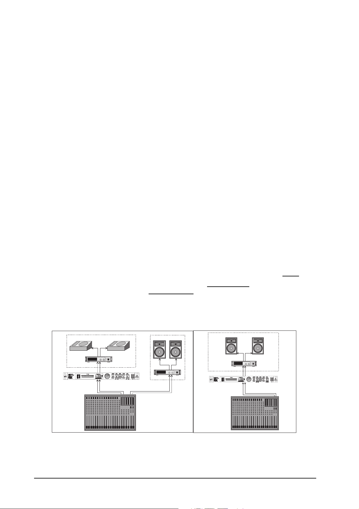
The most probable use for the FEEDBACKDESTROYERPRO is feedback suppression in a stage monitor
system or in a PA system. The unit should be placed between your console and the poweramplifiers.
1. First, connect the unit as seen below.
2. Check the operating level switch on the back panel. For most PAs, this should be set to +4dB.
3. On power-up, the Jog Wheel can select any of 10 programs. Programs 13 give you instant feedback
suppression for all 12 filters. Choose Program 8 or 10 for stereo processing of the master output.
+ Note that the Bypass switch can be either Off or On, but NOT flashing! When Bypass is flashing,
the whole unit is bypassed. But in the other two modes, filters set to Auto or Single Shot will
still operate.
Monitor System
Monitor Out
P.A. System
Master Out
P.A. System
Master Out
Fig. 1.1: Monitor application Fig.1.2: PA application
+ If you are using the FEEDBACKDESTROYERPRO for two separate monitor channels the L & R
Engines should not be coupled.
8
1. INTRODUCTION
On start-up; all active filters (AU/SI) are indicated by flashing LEDs. When feedback has been detected and
dealt with, the LED stops flashing. When all filters are set the oldest automatic filter starts flashing, indicating
that it will be the next filter to handle new feedback. Parametric filters are also indicated by a non-flashing LED.
In Single Shot mode the filter will not release a setting which has been achieved until you manually change it.
This is particularly useful with problems at discrete frequencies like turntable resonances and fixed microphone and monitor positions. If feedback is detected the filter will deal with that frequency and the status of that
filter will change to Locked (LO). It will only widen its bandwidth or increase the attenuation but it will not
release that setting to destroy a new feedback. In Auto mode the oldest filter will be released to destroy a new
feedback.
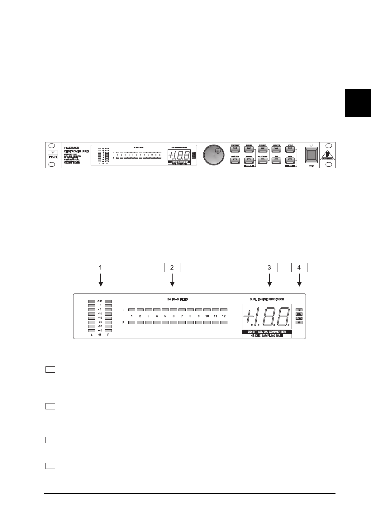
1.4 Control elements
Fig. 1.1: FEEDBACKDESTROYERPRO front panel
The BEHRINGER FEEDBACK DESTROYER PRO is equipped with ten parameters keys, one jog wheel
(rotary control) which is used to alter the selected parameter or preset and a numeric LED display. Each of the
24 filters has one LED assigned to it, which informs you about the status of the filter. By means of an 8-stage
LED meter each of the two fully independent channels can be monitored.
E
1.4.1 Front panel control elements
Fig. 1.2: Display section DSP1100P
1
The two LED chains read the output signal level indB, referenced to the internal digital maximum. If the
FEEDBACK DESTROYER PRO is set to Total Bypass mode, the level meter displays the input level.
+ Please note that the nominal level of the FEEDBACK DESTROYER PRO can be selected with
the +4dBu/-10dBV switch located on the back panel.
2
The FEEDBACK DESTROYER PRO features 24 filters which can be monitored conveniently with the
indicators next to the display. Twelve LEDs inform you about the status of the filters of each channel
(left/right). A bright LED announces that a filter has been set. Cyclically flashing LEDs idicate filters that
are searching in Single-Shot and Auto mode.
3
After power-up, the LED display reads the number of the preset last used. This clearly legible, 2½ digit
numeric display has plus/minus indicators to show that parameters are being incremented or decremented
in Edit mode.
4
The indicatorsHz,kHz, 1/60 anddB to the right of the display light up when you change the associated
parameters in Edit mode. For example, if you raise the level of a filter, the dB indicator lights up. A +
to the left of the preset number signals that the level is being increased.
1. INTRODUCTION
9
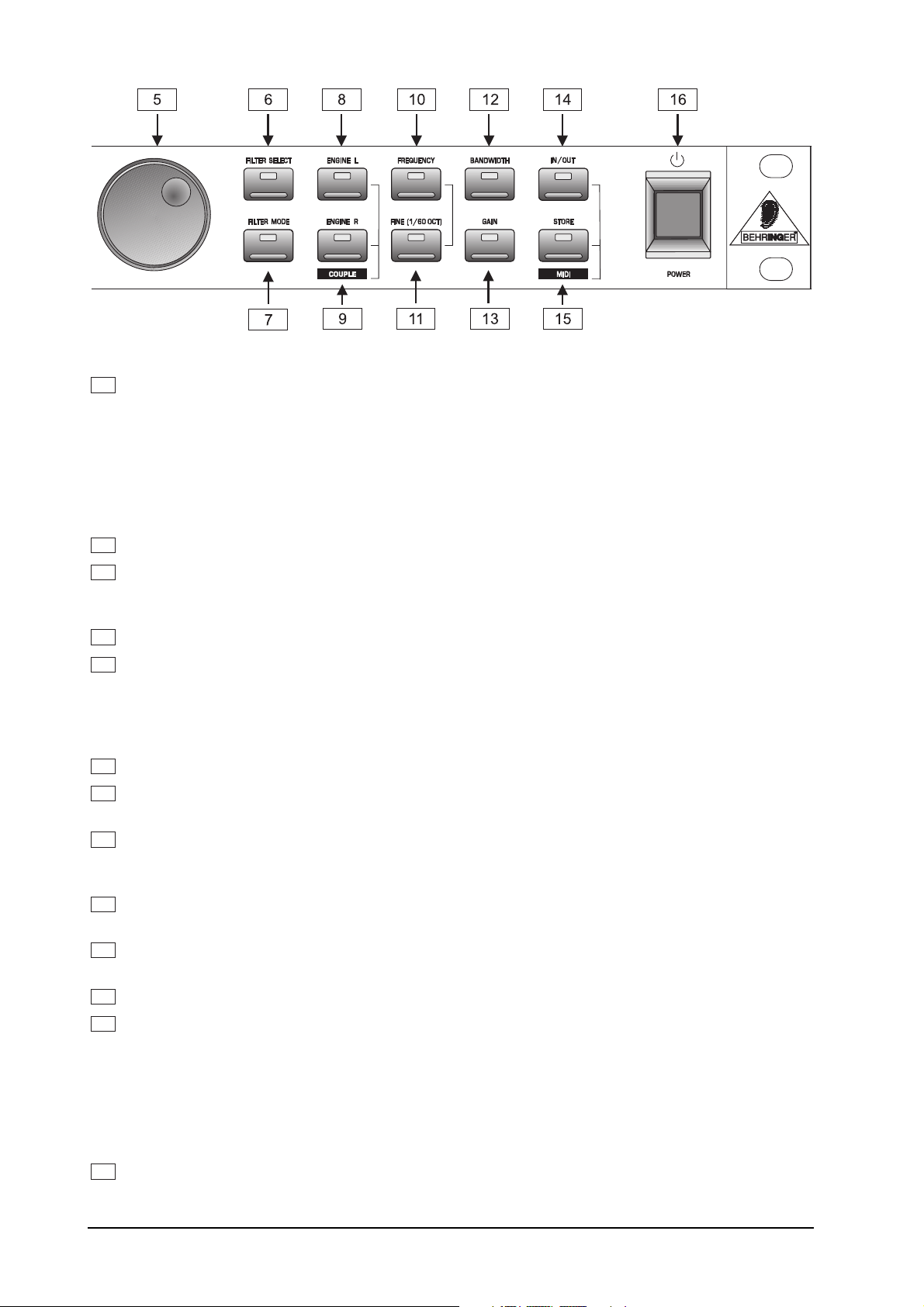
Fig. 1.3: Function keys and jog wheel
5
With the JOG WHEEL, a continuous rotary control, you can freely edit the selected parameters. Turn
the wheel clockwise to increase the values, or counterclockwise to reduce them.
+ As long as none of the edit functions to the right of the jog wheel has been selected, you can
use the wheel to select a program directly, which is shown by a dot lighting up in the display.
While this dot is on, you can select a program though its settings will not take immediate
effect. When the jog wheel has not been touched for one second, the LED in the display
disappears and the program is loaded.
6
With FILTERSELECT activated you use the jog wheel to select one of the 12 filters per channel.
7
The FILTERMODE key gives you access to the four operating modes: OF, Parametric EQ (PA),
Single-Shot (SI) and Auto Mode (AU). In addition you can edit the threshold of feedback suppression
(-3 to -9dB) by pressing the FILTERMODE and the GAIN key together for about 1 seconds.
11
Use the ENGINE L key to select the left audio channel.
12
Use the ENGINE R key to select the right audio channel. If you wish to process the left and right audio
channels simultaneously (COUPLE mode), press both ENGINE keys together. In couple mode both
engine LEDs light up. Whenever you edit one of the two audio channels and then switch to couple mode,
the parameters of the active channel will be copied to the other; i.e. if you press ENGINE L before
ENGINE R, left will be copied to right.
8
Use the ENGINEL key to select the left audio channel.
9
Use the ENGINER key to select the right audio channel. If you wish to process the left and right
channels simultaneously (Couple mode), press both Engine keys at the same time.
10
Press the FREQUENCY key to select the frequency you wish to process. The
FEEDBACKDESTROYERPRO splits up the adjustable frequency range (20Hz to 20kHz) into the 31
standard ISO values of a graphic EQ (see 6.1).
11
The FINE key allows you to fine tune the standard ISO frequencies (in 1/60-octave steps) within a tuning
range of 1/3 octave (-9/60 to +10/60).
12
BANDWIDTH determines the filter bandwidth of the selected filter. The adjustable value ranges from
2 octaves (120/60 octave) down to 1/60 octave.
13
The GAIN key sets the desired boost/cut of the selected filter indB (+16dB / -48dB).
14
The IN/OUT key allows for optional bypassing of the parametric filters or all filters. By shorty pressing
the IN/OUT key only the parametric filters will be deactivated and the green LED ends up lighting. Hold
down the IN/OUT key for about two seconds to deactivate all filters. A cyclically flashing LED will
indicate this Total-Bypass mode. One further pressing reactivates all filters. The LED flickers when
relevant MIDI data is received.
+ Please, use the Total-Bypass function only with utmost caution because by deactivation, the
FEEDBACK DESTROYER PRO possibly unlocks suppressed feedbacks.
15
Any modifications made to a preset can be stored with the help of the STORE key. Ten presets are
available on the FEEDBACK DESTROYER PRO. Press the IN/OUT and the STORE keys, the
FEEDBACK DESTROYER PRO automatically enters MIDI mode.
10
1. INTRODUCTION
Loading...