


Dialog+ SW 9.xx
S e r v i c e M a n u a l
E n g l i s h
Edition 1 -2010
M.KAY Dialog+ SW9xx SM EN 1-2010
|
S e r v i c e M a n u a l |
|
|
Dialog+ SW 9.xx |
1 / 2 0 1 0 |
I |
|
|
|
|
|
Contact your Local B. Braun Representative for Service Support
B. Braun Avitum AG
34209 Melsungen
Germany
Tel. No.: +49 5661 713500 (Günter Nissen) E-Mail: guenter.nissen@bbraun.com
BA-TE-DE08C M.KAY - Dialog+ SW9xx_sm_TOC_1-2010.doc/pdf <100329> yymmdd
B. Braun Avitum AG

|
S e r v i c e M a n u a l |
|
|
Dialog+ SW 9.xx |
1 / 2 0 1 0 |
II |
|
|
|
|
|
Valid for the following machine type:
|
|
|
|
|
|
|
|
|
|
|
|
|
|
|
|
|
|
|
|
|
|
|
|
|
|
|
|
|
|
|
|
|
|
|
|
|
|
|
|
|
|
|
|
|
|
|
|
|
|
|
For Software ≥ 9.xx |
|
|
||||||||||||||
|
|
|||||||||||||||
|
|
|||||||||||||||
|
|
|||||||||||||||
Dialog+: |
|
from serial no. 100000 |
||||||||||||||
Dialog+ HDF-Online: |
|
from serial no. 150000 |
||||||||||||||
Registration Number:
Service Manuals with a registration number are included in the update service!
BA-TE-DE08C M.KAY - Dialog+ SW9xx_sm_TOC_1-2010.doc/pdf <100329> yymmdd
B. Braun Avitum AG
|
S e r v i c e M a n u a l |
|
|
Dialog+ SW 9.xx |
1 / 2 0 1 0 |
III |
|
|
|
|
|
Copyright
Commissioning and Service
Prevent Electrical Shock Hazard
|
ESD Information |
|
! |
High Voltage |
|
in TFT Monitor |
||
|
Protective Conductor in TFT Housing
TSM Service Program
Software
Therapy Mode
Calibration
Tubing
Wiring
Prevent Chemical Burns and Scalding
Contaminated Machines
Cover in Rear Door
O-Rings
Figures
Fuses
Spare Parts
Disposal and Taking Back
of Spare Parts
System Configuration
Function Check
This document is the property of B. Braun Avitum AG with all rights reserved.
Only trained personnel must service the Dialog+, i.e. repair, maintenance, software installation, firmware update, retrofitting and commissioning of the Dialog+.
Servicing must only be performed with proper tools, calibration equipment and be in accordance with the most recent revision of this service manual/technical information, which must be clearly and thoroughly understood.
Switch off the Dialog+ and disconnect unit from mains if you have to open the machine for servicing. Do not touch any exposed wiring or conductive surfaces while the Dialog+ is opened. The voltages present when electrical power is connected to the Dialog+ can cause serious injury or death.
Pay attention to ESD information, because electronic components are sensitive to electrostatic discharges.
If a battery option is present in the machine:
High voltage can be present at the backlight inverter board BIB in the TFT monitor, even if the machine has been disconnected from mains. Pull out the battery compartment in the base platform and switch off the battery voltage before opening the machine.
If the TFT housing had to be opened during a service job, the tight seat of the protective conductors in the TFT housing must be checked.
Only activate the TSM service program for service activities. It is prohibited to connect a patient to the Dialog+ and to run a therapy if the TSM service program is activated in the Dialog+. If the TSM service program is activated the complete alarm system is disabled. The TSM service program is started in the service mode: digital board, service switch S1, position 2.
The software is installed in the software mode: digital board, service switch S1, position 3.
After completion of all procedures switch back to the therapy mode: digital board, service switch S1, position 0.
Only perform a calibration after the Dialog+ has reached working temperature and the machine was disinfected and decalcified. Save the calibration data (CFC) before you exit the TSM service program: TSM Main Menu, File Operations, Save Calibration Data.
Tubing must be replaced only by the same tubing type/length and identical installation manner.
Make sure that the tubings in the machine are not kinked or twisted after servicing (e.g. if sub-racks are pulled out and inserted again). The tubing must not touch moving/rotating components (e.g. motors of gear pumps).
Wiring must be replaced only by the same cable type/length and identical installation manner. The cables must not touch moving/rotating components (e.g. motors of gear pumps).
During servicing on running machines: prevent chemical burns and scalding of the skin due to the penetration of disinfectant or hot liquid.
Protective gear should be worn in case of servicing of assumed contaminated machines.
Servicing of mechanical assembly groups (components in contact with fluid): the cover for the switch mode power supply microcontroller SMPS-MC in the rear door must be assembled during servicing because it serves as a spray protection.
Always check o-rings from disassembled groups/components and replace if necessary.
The displayed figures can differ slightly from the machines on site, due to different hardware statuses.
If fuses are replaced they must exactly match the type and rating specified by the manufacturer in the spare parts list/technical information. Where applicable: fuses must be approved by UL/CSA.
Only use original spare parts manufactured and sold by B. Braun Avitum AG.
Dispose spare parts (e.g. boards or batteries) according to local disposal guidelines or send back to B. Braun Avitum AG free of charge (see chapter 7).
The system configuration saved on a diskette must be downloaded to an other Dialog+ machine only if:
•the hardware matches and
•the identical software version number is present.
Check the respective function of the assembly group/component after servicing. A complete function check must be performed after every service, according to the operating manual.
BA-TE-DE08C M.KAY - Dialog+ SW9xx_sm_TOC_1-2010.doc/pdf <100329> yymmdd
B. Braun Avitum AG

|
S e r v i c e M a n u a l |
|
|
Dialog+ SW 9.xx |
1 / 2 0 1 0 |
IV |
|
|
|
|
|
Table of Contents |
Page |
|
|
|
|
1. |
Installation and Commissioning |
1-1 |
|
|
|
2. |
Technical System Description |
2-1 |
|
|
|
3. |
Repair Instructions |
3-1 |
|
|
|
4. |
TSM Service Program |
4-1 |
|
|
|
5. |
Technical Safety Inspection with Preventive Maintenance |
5-1 |
|
|
|
6. |
Flow, Wiring and Tubing Diagrams |
6-1 |
|
|
|
7. |
Spare Parts List |
7-1 |
|
|
|
8. |
Appendix |
8-1 |
|
|
|
8.1 |
ESD/EMC Information |
8-2 |
|
|
|
8.1.1 |
Electrostatic Discharge ESD |
8-2 |
|
|
|
8.1.2 |
Electromagnetic Compatibility EMC |
8-4 |
|
|
|
8.2 |
Technical Information |
- |
|
|
|
8.3 |
Assembly Instructions |
- |
|
|
|
8.4 |
Field Service Information |
- |
|
|
|
8.5 |
Instruction Leaflets |
- |
|
|
|
9. |
Edition/Updates Service Manual |
9-1 |
BA-TE-DE08C M.KAY - Dialog+ SW9xx_sm_TOC_1-2010.doc/pdf <100329> yymmdd
B. Braun Avitum AG
|
S e r v i c e M a n u a l |
|
|
Dialog+ SW 9.xx |
1 / 2 0 1 0 |
V |
|
|
|
|
|
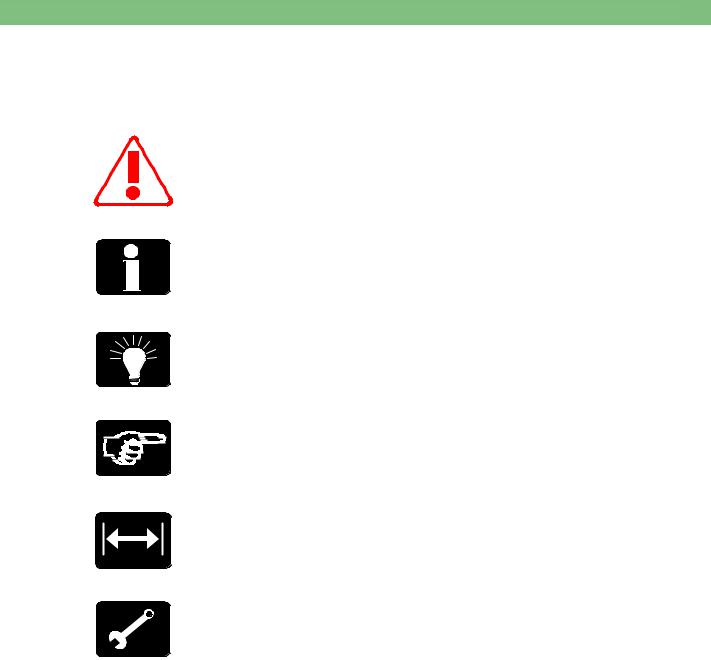
Conventions
Symbol |
Description |
Attention
The symbol gives information, which are safety relevant for the Dialog+ and must be observed.
Information
The symbol gives additional information, which should be observed.
Tips
The symbol gives additional hints, which can be helpful.
Handling
The symbol gives information for a handling at or in the machine, i.e. during a calibration, disassembly or assembly.
Calibration
The symbol appears for necessary calibration measures.
Calibration Equipment/Tools
The symbol gives remarks for necessary calibration equipment/tools, i.e. during a calibration, disassembly or assembly.
BA-TE-DE08C M.KAY - Dialog+ SW9xx_sm_TOC_1-2010.doc/pdf <100329> yymmdd
B. Braun Avitum AG

|
S e r v i c e M a n u a l |
|
|
Dialog+ SW 9.xx |
1 / 2 0 1 0 |
VI |
|
|
|
|
|
Service Manual
Service Training
Technical Safety Inspection
Instructions for Use
ESD/EMC Information
Spare Parts
Calibration Service
The edition of this service manual is for the maintenance and repair of the Dialog+ machine with a software ≥ 9.01. The service manual is subject to amendments.
A service training is essential to meet the B. Braun standard operating procedures for qualified service and support.
The user of this documentation should only use this documentation in combination with a participation in a B. Braun service training.
The user of this documentation should have the following qualifications and prerequisites:
1.Mechanics, digital/analogue techniques, optoelectronics, measurement and PC techniques.
2.Participation in a B. Braun service training to accomplish qualified maintenance, repair and service support.
3.Availability of approved and calibrated test equipment and tools given in this service manual.
Contact your local B. Braun representative or dealer for detailed information concerning training courses.
B. Braun Avitum AG
34209 Melsungen, Germany
Tel.: |
+49 5661 712718 |
Fax.: |
+49 5661 752718 |
E-Mail: |
marina.ritz-nickel@bbraun.com |
Perform regular technical safety inspections as described in chapter 5 of this service manual to ensure the safety of the machine.
An instructions for use can be ordered at your local B. Braun representative or dealer.
Please observe the ESD/EMC information (see appendix for additional information):
•ESD: electrostatic discharge
•EMC: electromagnetic compatibility
Only original spare parts manufactured and sold by B. Braun are applicable. Please provide part number and description respectively when ordering any spare parts. Please order your spare parts at your local B. Braun representative or dealer.
B. Braun Avitum AG
34209 Melsungen, Germany
Tel. No.: +49 5661 713662
E-Mail: heike.sinning@bbraun.com dialysetechnik.melsungen@bbraun.com
The main assembly groups are defined according to the spare parts list. The main assembly groups are especially:
•All pcb's (printed circuit boards)
•Pumps
•DF block
•Ultrafiltration
•Blood leak detector
•Safety air detector
•Heater
Tamper or repairs in these assembly groups are not permissible (due to calibration, ESD, multi-layer pcb's and the application of SMT (SMT = surface mounted technology).
All calibration devices must be approved and registered with an identification number. The calibration equipment is subject to the B. Braun calibration service and must be checked and recalibrated in regular intervals, to meet the B. Braun standard operating procedures SOPs. Only approved and registered calibration equipment must be applied for servicing.
BA-TE-DE08C M.KAY - Dialog+ SW9xx_sm_TOC_1-2010.doc/pdf <100329> yymmdd
B. Braun Avitum AG

|
1 . Commissioning |
|
|
Dialog+ SW 9.xx |
1 / 2 0 1 0 |
1 - 1 |
|
|
|
|
|
Copyright
Commissioning and Service
Prevent Electrical Shock Hazard
ESD Information |
|
|
High Voltage |
! |
|
in TFT Monitor |
||
|
Protective Conductor in TFT Housing
TSM Service Program
Software
Therapy Mode
Calibration
Prevent Chemical Burns and Scalding
Contaminated Machines
Cover in Rear Door
Tubing
Wiring
Fuses
Spare Parts
Instructions for Use
Check Machine
Commissioning
Electrical Installation
Mains Voltage Supply
Ambient Temperature
Water Installation
Water Quality
Central Hot Cleaning System
This document is the property of B. Braun Avitum AG with all rights reserved.
Only trained personnel must service the Dialog+, i.e. repair, maintenance, software installation, firmware update, retrofitting and commissioning of the Dialog+.
Servicing must only be performed with proper tools, calibration equipment and be in accordance with the most recent revision of this service manual/technical information, which must be clearly and thoroughly understood.
Switch off the Dialog+ and disconnect unit from mains if you have to open the machine for servicing.
Do not touch any exposed wiring or conductive surfaces while the Dialog+ is opened. The voltages present when electrical power is connected to the Dialog+ can cause serious injury or death.
Pay attention to ESD information, because electronic components are sensitive to electrostatic discharges.
If a battery option is present in the machine:
High voltage can be present at the backlight inverter board BIB in the TFT monitor, even if the machine has been disconnected from mains. Pull out the battery compartment in the base platform and switch off the battery voltage (remove fuse) before opening the machine.
If the TFT housing had to be opened during a service job, the tight seat of the protective conductors in the TFT housing must be checked.
Only activate the TSM service program for service activities. It is prohibited to connect a patient to the Dialog+ and to run a therapy if the TSM service program is activated in the Dialog+. If the TSM service program is activated the complete alarm system is disabled. The TSM service program is started in the service mode: digital board, service switch S1, position 2.
The software is installed in the software mode: digital board, service switch S1, position 3.
After completion of all procedures switch back to the therapy mode: digital board, service switch S1, position 0.
Only perform a calibration after the Dialog+ has reached working temperature, and the machine was disinfected and decalcified. You should save the calibration data to the hard disk drive before you exit the TSM service program: TSM Main Menu, File Operations, Save Calibration Data.
During servicing on running machines: prevent chemical burns and scalding of the skin due to the penetration of disinfectant or hot liquid.
Protective gear should be worn in case of servicing of assumed contaminated machines.
Servicing of mechanical assembly groups (components in contact with fluid): the cover in the rear door must be assembled during servicing because it serves as a spray protection for the SMPS-MC.
Tubing must be replaced only by the same tubing type/length and identical installation manner.
Make sure that the tubings in the machine are not kinked or twisted after servicing (e.g. if sub-racks are pulled out and inserted again). The tubing must not touch moving/rotating components (e.g. motors of gear pumps).
Wiring must be replaced only by the same cable type/length and identical installation manner. The cables must not touch moving/rotating components (e.g. motors of gear pumps).
If fuses are replaced they must exactly match the type and rating specified by the manufacturer in the spare parts list/technical information. Where applicable: fuses must be approved by UL/CSA.
Only use original spare parts manufactured and sold by B. Braun Avitum AG.
Please pay attention to the information in the instructions for use
Check completeness of machine and transport damages after unpacking.
Do not start machine if a safe operation is not guaranteed.
The electrical installation must correspond with national regulations for initial operation of the unit (e.g. IEC publications). The machine must not be operated in hazardous locations or rooms. The potential equalisation must be in accordance with national requirements (e.g. IEC publications)
The mains voltage supply must correspond with the mains voltage on the unit type plate!
Before the Dialog+ is switched on the machine must have room temperature (see instructions for use, chapter 15).
The installation must be in accordance with national regulations e.g. DVGW work sheet W503 for haemodialysis equipment and VDE 0753 (rules of application for haemodialysis equipment).
A pipe disconnector is not necessary if a water softener or water softener with built-in reverse osmosis system is installed. A nonreturn valve and a bleed pipe are adequate. Please see DVGW work sheet W 503, section 4.4 and VDE 0753 part 4 (Rules of application for haemodialysis equipment).
Only water of the highest quality should be applied. Please consider the following, especially for bicarbonate dialysis:
•Inlet water shall be free of Mg++ and Ca++.
If the machine is connected to a central hot cleaning system a high temperature tubing must be used for the water inlet.
BA-TE-DE08C M.KAY Dialog+ SW9xx_SM_Chapter 1-1_1-2010.doc/pdf <110301> yymmdd
B. Braun Avitum AG
|
1 . Commissioning |
|
|
Dialog+ SW 9.xx |
1 / 2 0 1 0 |
1 - 2 |
|
|
|
|
|
2
3
4

5

6
7
8
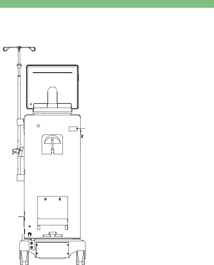
Fig.: Dialog+ Rear View
Legend
1. Type Plate
2. Canister Holder
3. Potential Equalisation Bolt
4. Main Cord
5. Central Concentrate Supply Option
1 6. Tubing Connection Water Inlet
•PVC tubing 10 x 3 mm (red)
(fasten with two single ear clamps 19.5)
•Tubing length: approx. 3 m
6.1Tubing Connection Water Inlet for Osmosis Device with Hot Disinfection of the Loop Line
•Silicone tubing 8 x 3.2 mm (high temperature tubing, red) (fasten with two single ear clamps 19.5)
7. Tubing Connection Dialysate Outlet
•PVC tubing 10 x 3 mm (black)
(fasten with a single ear clamp 19.5 and a tubing clamp 12-
20mm)
•Tubing length: approx. 3 m
•Drain height: max. 80 cm
8.Emergency Power Supply/Battery Option
BA-TE-DE08C M.KAY Dialog+ SW9xx_SM_Chapter 1-1_1-2010.doc/pdf <110301> yymmdd
B. Braun Avitum AG

|
1 . Commissioning |
|
|
Dialog+ SW 9.xx |
1 / 2 0 1 0 |
1 - 3 |
|
|
|
|
|
Table of Contents |
Page |
|
1.1 |
Commissioning Check List |
1-4 |
1.1.1 |
Measurement Circuits for the Measurement of the Electrical |
1-6 |
|
Safety According to EN 62353/60601-1 |
|
BA-TE-DE08C M.KAY Dialog+ SW9xx_SM_Chapter 1-1_1-2010.doc/pdf <110301> yymmdd
B. Braun Avitum AG
|
1 . Commissioning |
|
|
Dialog+ SW 9.xx |
1 / 2 0 1 0 |
1 - 4 |
|
|
|
|
|
1.1Commissioning Check List
For Dialog+ SW 9.xx |
The commissioning (putting into service) shall be performed and documented before the machine |
||||
|
is handed over to the responsible organisation (user), according to the specified check list, with |
||||
|
reference to the service manual and instructions for use. |
||||
|
REF {Type/Typ}:................................................. |
|
SN {Serien-No./Nr.}: ................................................ |
||
|
Year of Purchase: ....................... |
Responsible Organisation (User): ..................................................... |
|||
|
......................................................................................................................................................................... |
|
|||
|
Operating Hours: .................................... |
h |
Inventory No.: .................................................................. |
||
|
SW Version: ........................................... |
|
|
|
|
Manufacturer: |
B. Braun Avitum AG |
|
|
|
|
|
34209 Melsungen, Germany |
|
|
|
|
Check List |
|
|
|
||
|
|
|
OK |
|
|
Note: Text in { } brackets is information for the execution of the check list!
1. |
Visual Inspection |
|
|
1.1{Machine: clean/complete; no damages/moisture influences or loose assemblies; no moveable parts touching tubings or wires; casters are moveable; type plate legible}
1.2{Check tight seat and damages of mains supply (power supply cord, strain relief), potential equalisation cable, staff call/data lines (if present) and connectors}
2.Protective Earth Resistance According to EN 62353
2.1Protective Earth Resistance:
|
< 0.3 [Ω] |
{note highest value}: ................................................ |
[Ω] |
|
|
{(Machine incl. power supply cord. Move the power supply cord during the check. Thus possible loose connections can be detected. Data lines and |
|
||
|
potential equalisation cable must not be connected during the check of the of the protective earth resistance (see figure 1)} |
|
|
|
|
{Measurement points:} |
|
|
|
|
{Exterior: Potential equalisation bolt, rinsing bridge (dialyser inlet and outlet)} |
|
|
|
|
{Interior: Heater body (top), rear door (top left corner), frame (rear), housing cover (top left), front door (top left)} |
|
|
|
|
{Monitor: Monitor (one of the screws in the front panel/housing} |
|
|
|
|
|
|
|
|
3. |
Install Machine |
|
|
|
|
|
|
||
3.1{Connect water inlet to the metal tubing connector and fasten with single ear clamp. Connect dialysate outlet to plastic tubing connector and fasten with tubing clamp.}
3.2{Connect central supply for concentrate (central supply option) and deaerate tubings}
3.3{Assemble holder for disinfectant (if option present)}
3.4{Assemble dialyser holder}
3.5{Assemble filter holder. Insert DF filter (option)}
3.6{Assemble DF filter/HDF filter (if option present)}
4.Function Inspection
{ P a y a t t e n t i o n t o t h e f i l l i n g p r o c e d u r e o f t h e m a c h i n e t o p r e v e n t d r y r u n o f t h e h e a t e r ! } |
|
|
|
|||
|
|
|
|
|
|
|
4.1 |
Switch on machine, fill and rinse: |
- {Switch machine in Test 1.10 Degassing and Heating menu and fill with water until |
|
|
||
|
|
|||||
|
|
water flows out of the dialysate outlet. Then rinse in disinfection (approx. 5 minutes).} |
|
|
||
4.2 |
Automatic Blood Pressure Measurement ABPM |
|
Option present |
no |
yes |
|
4.2.1 |
ABPM Option: |
- Measurement on a test person is plausible |
|
|
|
|
4.3 |
Customer Specific System Setting: |
- {Switch machine in TSM Service Program: Execute Treatment Support (calibrate PE offset for |
|
|||
|
|
altitudes > 1000 m} |
|
|
|
|
BA-TE-DE08C M.KAY Dialog+ SW9xx_SM_Chapter 1-1_1-2010.doc/pdf <110301> yymmdd
B. Braun Avitum AG

|
|
1 . Commissioning |
|
|
|
|
Dialog+ SW 9.xx |
1 / 2 0 1 0 |
1 - 5 |
||
|
|
|
|
|
|
|
Check List |
|
|
|
|
|
|
OK |
|
||
|
Note: Text in { } brackets is information for the execution of the check list! |
............................................SN {Serien-No./Nr.} |
|
|
|
5.Setting into Service According to Instructions for Use with Electrical Safety Check According to EN 62353/EN 60601-1
5.1 |
Applied Accessories/Disposables: |
- Applied line system: |
|
|
|
|
Name: ...................................................................................................................................................................................... |
|
|
|
|
|
|
|
5.2 |
Switch on machine: |
- Self-test passed {and 15 minutes therapy with UF safety check} |
|
|
|
|
- Ultrafiltration comparison measurement 15 minutes with UF rate 500 ml/h: ......................... |
[ml] |
|
|
|
(125 ml UF volume ±15 ml) |
|
|
5.3 |
Temperature: |
- Comparison measurement {at dialyser coupling}, at 37 oC (-1.5; +0.5): ......................... |
[oC] |
|
5.4 |
Conductivity: |
- Comparison measurement {at dialyser coupling}, e.g. 14.3 mS/cm (±0.2): ................. |
[mS/cm] |
|
5.5Equipment Leakage Current:
{All water connections and data lines must be connected during the check of the equipment leakage current (see figure 2)}
≤ 0.5 [mA] |
- During heat-up phase {change mains polarity and note highest value}: ....................... |
[mA] |
5.6Patient Leakage Current:
{All water connections and data lines must be connected during the check of the patient leakage current (see figure 3)}
|
< 10 [µA] AC |
- Under normal conditions {at dialyser coupling}, conductivity at 13 – 15 mS/cm: ........................ |
[µA] |
5.7 |
Safety Air Detector (SAD): |
- Test alarm function (visual/audible) passed |
|
5.8 |
Disinfection: |
- Start |
|
Applied Measurement Equipment:
Electrical Safety: ........................................................................................ |
* ID/Serial No.: ................................. |
Conductivity: ............................................................................................... |
* ID/Serial No.: ................................. |
Temperature: ............................................................................................... |
* ID/Serial No.: ................................. |
Pressure: ....................................................................................................... |
* ID/Serial No.: ................................. |
Balance: ........................................................................................................ |
* ID/Serial No.: ................................. |
Pressure Manometer: ............................................................................... |
* ID/Serial No.: ................................. |
Other Measurement Device: ................................................................... |
* ID/Serial No.: ................................. |
......................................................................................................................... |
* ID/Serial No.: ................................. |
* If applicable, please enter the type and identification number of the equipment used.
Comments:
..........................................................................................................................................................................................................................................................
..........................................................................................................................................................................................................................................................
..........................................................................................................................................................................................................................................................
Next Inspection Date:
The commissioning was performed and the machine was hand over to the responsible organisation (user).
............................................................................................................................................................
Name Service Technician: |
Name of Company: |
................................................................................... |
|
...................................................................................Date/Signature |
................................................................. |
|
BA-TE-DE08C M.KAY Dialog+ SW9xx_SM_Chapter 1-1_1-2010.doc/pdf <110301> yymmdd
B. Braun Avitum AG
Dialog+ SW 9.xx 1 . Commissioning
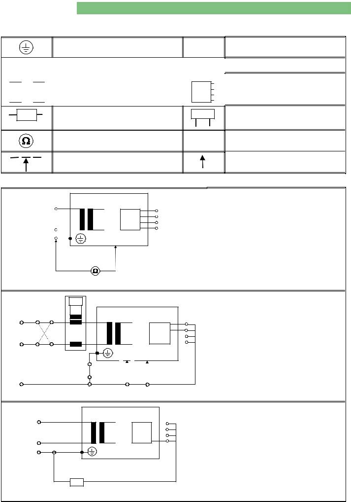
1.1.1Measurement Circuits for Measurement of Electrical Safety According to IEC 62353/60601-1
Protective earth (ground)
L, N |
|
Supply mains terminals |
PE |
|||
|
|
|
|
|
||
|
|
|
|
|
||
|
MP |
|
Mains part |
AP |
||
|
|
|
|
|
|
|
|
|
|
|
|
|
|
MD |
Measuring device |
M |
|
Resistance measurement equipment
Part of enclosure not protectively earthed
1 / 2 0 1 0 |
1 - 6 |
Protective earth terminal
Applied part
Residual current meter with frequency response as MD
Connection to accessible conductive parts
Table 1: Legend of Abbreviations and Symbols
L |
MP |
AP |
|
|
|
||
N |
|
|
|
PE |
|
|
|
Fig. 1: Protective Earth Resistance |
|
|
|
M |
|
|
|
L(N) |
MP |
AP |
|
L |
|||
|
|
||
N |
|
|
|
N(L) |
|
|
|
PE |
|
|
|
Fig. 2: Equipment Leakage Current |
|
|
|
L |
MP |
AP |
|
|
|
||
N |
|
|
|
PE |
|
|
|
MD |
|
|
|
Fig. 3: Patient Leakage Current |
|
|
Protective Earth Resistance
Test current: ≥ 200 mA
The test current must be measured in both directions.
Equipment Leakage Current:
•Differential Measurement
Patient Leakage Current
BA-TE-DE08C M.KAY Dialog+ SW9xx_SM_Chapter 1-1_1-2010.doc/pdf <110301> yymmdd
B. Braun Avitum AG

|
2 . Technical System Description |
|
|
Dialog+ SW 9.xx |
1 / 2 0 1 0 |
2 - 1 |
|
|
|
|
|
Table of Contents |
Page |
|
General Information |
2-4 |
|
2.1 |
Overview Sub-Racks |
2-5 |
2.1.1 |
Legend Overview Sub-Racks |
2-5 |
2.2 |
Top Level Sub-Rack |
2-6 |
2.2.1 |
Legend Top Level Sub-Rack |
2-6 |
2.3 |
Basic Board BB |
2-7 |
2.3.1 |
Legend Basic Board |
2-7 |
2.4 |
Power Board Valves PBV |
2-8 |
2.4.1 |
Legend Power Board Valves |
2-8 |
2.5 |
Power Board Motors PBM |
2-9 |
2.5.1 |
Legend Power Board Motors |
2-9 |
2.6 |
Digital Board DB |
2-10 |
2.6.1 |
Legend Digital Board |
2-10 |
2.7 |
Analog Board AB |
2-11 |
2.7.1 |
Legend Analog Board |
2-11 |
2.8 |
HDF Online Board HOB |
2-12 |
2.8.1 |
Legend HDF Online Board |
2-12 |
2.9 |
UF Sub-Rack |
2-13 |
2.9.1 |
Legend UF Sub-Rack |
2-13 |
2.10 |
UF Sub-Rack HDF Online |
2-14 |
2.10.1 |
Legend UF Sub-Rack HDF Online |
2-14 |
2.11 |
DF Sub-Rack |
2-15 |
2.11.1 |
Legend DF Sub-Rack |
2-15 |
2.12 |
Water Sub-Rack |
2-16 |
2.12.1 |
Legend Water Sub-Rack |
2-16 |
2.13 |
Rinsing Bridge |
2-17 |
2.13.1 |
Legend Rinsing Bridge |
2-17 |
2.14 |
Rear Door |
2-18 |
2.14.1 |
Legend Rear Door |
2-18 |
2.15 |
Switch Mode Power Supply Microcontroller SMPS-MC |
2-19 |
2.15.1 |
Legend Switch Mode Power Supply Microcontroller |
2-19 |
2.16 |
TFT Monitor |
2-20 |
2.16.1 |
Legend TFT Monitor |
2-20 |
2.17 |
Front Door |
2-21 |
2.17.1 |
Legend Front Door |
2-21 |
BA-TE-DE08C M.KAY Dialog+ SW9xx_sm_Chapter 2_1-2010.doc/pdf <100329> yymmdd
B. Braun Avitum AG

|
2 . Technical System Description |
|
|
Dialog+ SW 9.xx |
1 / 2 0 1 0 |
2 - 2 |
|
|
|
|
|
2.18 |
Level Regulation Module |
2-22 |
2.18.1 |
Legend Level Regulation Module |
2-22 |
2.18.2 |
Flow Diagram Level Regulation Module |
2-23 |
2.19 |
Flow Diagrams |
2-24 |
2.19.1 |
Dialog+ |
2-24 |
2.19.2 |
Dialog+ with BIC Option and DF Filter Option |
2-25 |
2.19.3 |
Dialog+ HDF Online |
2-26 |
2.19.4 |
Legend Flow Diagram |
2-27 |
2.20 |
Description Flow Diagram |
2-29 |
2.20.1 |
Water Inlet Section with Water Block |
2-29 |
2.20.2 |
Degassing Circuit with Temperature System |
2-30 |
2.20.3 |
Dialysate Processing |
2-31 |
2.20.4 |
Central Bicarbonate and Concentrate Supply (Option) |
2-32 |
2.20.5 |
BIC Cartridge Holder (Option) |
2-32 |
2.20.6 |
Balance Chamber System |
2-33 |
2.20.7 |
Working Principle Balance Chamber System |
2-33 |
2.20.8 |
Ultrafiltration and Rinsing Bridge |
2-35 |
2.20.9 |
Chemical Thermal Disinfection Program |
2-36 |
2.21 |
Block Diagram |
2-38 |
2.21.1 |
Legend Block Diagram |
2-39 |
2.22 |
Switch Mode Power Supply Microcontroller SMPS-MC |
2-42 |
2.22.1 |
Block Diagram SMPS-MC |
2-42 |
2.22.2 |
System Integration SMPS-MC |
2-43 |
2.22.3 |
Component Layout SMPS-MC |
2-44 |
2.22.4 |
Wiring Diagram SMPS-MC with Battery Option |
2-45 |
2.22.5 |
Description SMPS-MC |
2-46 |
2.22.6 |
Fuses |
2-48 |
2.22.7 |
Signals |
2-49 |
2.22.8 |
Internal Signals |
2-49 |
BA-TE-DE08C M.KAY Dialog+ SW9xx_sm_Chapter 2_1-2010.doc/pdf <100329> yymmdd
B. Braun Avitum AG

|
2 . Technical System Description |
|
|
Dialog+ SW 9.xx |
1 / 2 0 1 0 |
2 - 4 |
|
|
|
|
|
General Information
Top Level System
Low Level System
Operation is accomplished via a touch screen (TFT monitor). Two microprocessor systems control and monitor the machine.
The hardware concept consists of the following systems:
•Top Level System
•Low Level System
The top level system consists of the following components:
•Communication module
•Top level controller TLC (motherboard)
•Compact flash card CFC
•Options
The communication between the user and the machine is performed via the top level.
Example data exchange to communication module:
•Entry via input mask of the touch screen or keyboard
•Output via the output mask of the TFT monitor
Example data exchange to low level:
•Transmitting and receiving data from/to low level controller and supervisor on the digital board DB (LLD)
The low level system consists of the following components:
•Digital board DB (LLD)
•Analog board AB (LLA)
•Power board motors PBM
•Power board valves PBV
The low level controls and monitors all functions.
Data exchange to top level controller (motherboard):
•Transmitting and receiving data from/to low level supervisor
•Transmitting and receiving data from/to low level controller
Data exchange between low level controller to supervisor:
• Transmitting and receiving messages, data and commands
All sensor data are sent separately, via two serial bus systems, to the supervisor and controller via the analog board to the digital board. The actuators, motors and valves are driven via the power board valves PBV and power board motors PBM.
BA-TE-DE08C M.KAY Dialog+ SW9xx_sm_Chapter 2_1-2010.doc/pdf <100329> yymmdd
B. Braun Avitum AG

|
2 . Technical System Description |
|
|
|
|
|
|
|
|
|
|
|
|
|
|
|
|
|
|
|
|
|
|
|
|
|
|
|
|
|
|
|
|
|
|
|
|
|
|
|
|
|
|
|
||||||
Dialog+ SW 9.xx |
1 / 2 0 1 0 |
2 - 3 |
||||||||||||||||||||||||||||||||||||||||||||||||
|
|
|
|
|
|
|
|
|
|
|
|
|
|
|
|
|
|
|
|
|
|
|
|
|
|
|
|
|
|
|
|
|
|
|
|
|
|
|
|
|
|
|
|
|
|
|
|
|
|
|
|
|
|
|
|
|
|
|
|
|
|
|
|
|
|
|
|
|
|
|
|
|
|
|
|
|
|
|
|
|
|
|
|
|
|
|
|
|
|
|
|
|
|
|
|
|
|
|
|
|
|
For Software ≥ 9.xx
BA-TE-DE08C M.KAY Dialog+ SW9xx_sm_Chapter 2_1-2010.doc/pdf <100329> yymmdd
B. Braun Avitum AG
|
2 . Technical System Description |
|
|
Dialog+ SW 9.xx |
1 / 2 0 1 0 |
2 - 5 |
|
|
|
|
|
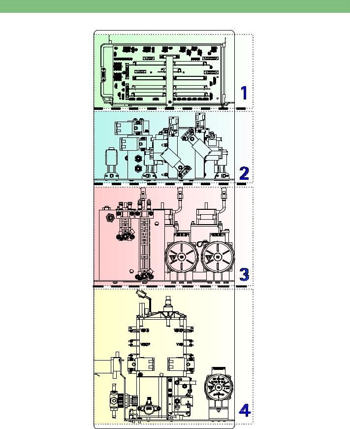
2.1Overview Sub-Racks
|
|
4 |
|
|
|
1 |
|
4 |
1 |
4 |
1 |
Fig. : Overview Sub-Racks Rear View Dialog+
2.1.1Legend Overview Sub-Racks
1 |
Top Level Sub-Rack |
3 |
DF Sub-Rack |
2 |
UF Sub-Rack |
4 |
Water Sub-Rack |
BA-TE-DE08C M.KAY Dialog+ SW9xx_sm_Chapter 2_1-2010.doc/pdf <100329> yymmdd
B. Braun Avitum AG
|
2 . Technical System Description |
|
|
Dialog+ SW 9.xx |
1 / 2 0 1 0 |
2 - 6 |
|
|
|
|
|
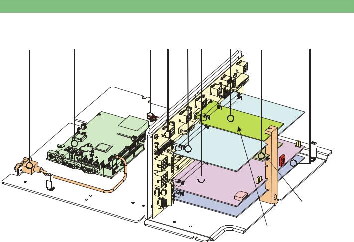
2.2Top Level Sub-Rack
1 |
2 |
3 4 5 6 |
7 |
8 |
9 |
Motherboard
USB: |
|
JP2 |
Service |
Power Board |
S1 |
SW |
||
|
Valves |
|
 Digital Board JP1
USB:
SW
Power Board Motors
Basic Board Analog Board
HDF Online Board
Fig. : Top Level Sub-Rack
2.2.1Legend Top Level Sub-Rack
1USB Port:
Service (FSU)/Software Installation TLC
2LX800 Motherboard
3Temperature Switch TS (closes at 50 ± 3 oC, opens at 35 ± 6 oC)
4Basis Board BB
5Power Board Valves PBV
6Digital Board DB (LLD):
USB Port: Software Installation LLC/LLS; Service-Switch S1; Jumper JP1/JP2
7HDF Online Board HOB
8Power Board Motor PBM
9Analog Board AB (LLA)
BA-TE-DE08C M.KAY Dialog+ SW9xx_sm_Chapter 2_1-2010.doc/pdf <100329> yymmdd
B. Braun Avitum AG
|
2 . Technical System Description |
|
|
Dialog+ SW 9.xx |
1 / 2 0 1 0 |
2 - 7 |
|
|
|
|
|
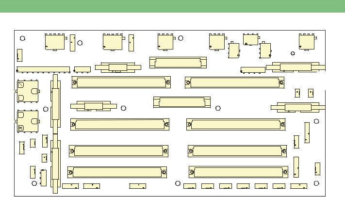
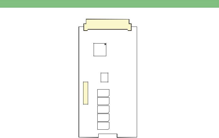
2.3Basic Board BB
|
|
P47 |
|
P9 |
|
P3 |
P2 |
P1 |
P4 |
P20 |
|
|
P48 |
|
|
|
|
P26 |
P8 |
P16 |
|
|
|
|
|
P11 |
P13 |
|
|
|
|
|
P5 |
|
1 |
|
P10 |
1 |
P59 |
|
|
|
1 |
P15 |
|
|
||
|
|
|
|
|
|
|
|
||||||
1 |
|
|
|
|
P21 |
|
|
|
P22 |
|
|
P57 |
P60 |
|
|
|
|
|
|
|
|
|
|
|
|||
P17 |
|
P24 |
|
|
|
|
|
|
|
|
|||
|
|
|
|
|
|
|
|
|
|
|
|||
|
|
|
|
P23 |
|
P25 |
|
|
|
|
|
P14 |
|
|
|
|
|
|
|
|
|
|
|
|
|
||
1 |
|
|
|
|
|
|
|
|
|
|
|
|
|
P54 |
|
|
|
P18 |
|
|
|
P19 |
|
|
|
P12 |
|
|
|
|
|
|
|
|
|
|
|
|
|
||
|
P58 |
P49 |
|
|
|
|
|
|
|
|
|
P27 |
|
P50 |
|
|
|
|
|
|
|
|
|
|
|
|
|
|
|
P51 |
P6 |
|
P33 |
|
|
|
P34 |
|
|
P42 |
|
|
|
|
|
|
|
|
|
|
|
|
|
|
|
|
P31 |
|
|
|
|
|
|
|
|
|
|
|
P36 |
|
P32 |
|
|
P40 |
|
|
|
P41 |
|
|
|
|
|
|
|
1 |
|
|
|
|
|
|
|
|
|
||
|
|
|
P39 |
P45 |
P38 |
P7 |
P30 |
P29 |
P28 |
P35 |
P37 |
P44 |
|
Fig. : Basic Board
2.3.1Legend Basic Board
P1 |
Degassing Pump EP |
P27 |
Membrane Position Sensors Balance Chamber MSBK |
P2 |
Venous Blood Pump BPV |
P28 |
Temperature Sensor Dialysate TSD |
P3 |
Arterial Blood Pump BPA |
P29 |
Temperature Sensor Heater Inlet TSHE |
P4 |
Outlet Flow Pump FPA |
P30 |
Degassing Temperature Sensor TSE |
P5 |
Safety Air Detector SAD |
P31 |
Level Sensor Upline Tank NSVB |
P6 |
Heparin Pump HP (HEP) |
P32 |
Blood Leak Detector BL |
P7 |
Air Separator Level Sensor LAFS |
P33/P34 |
Digital Board DB |
P8 |
BIC Pump BICP |
P35 |
Temperature Sensor BIC TSBIC |
P9 |
Concentrate Pump KP |
P36 |
Temperature Sensor Dialyser Inlet TSDE |
P10 |
All Valves (+ Option BIC) VALVES |
P37 |
Temperature Sensor Dialysate Supervisor TSD-S |
P11 |
Level Regulation LR |
P38 |
Pressure Sensor Dialysate Outlet PDA |
P12 |
DIABUS |
P39 |
Blood Side Pressure Sensor PBLOOD |
P13 |
HDF Online Board HOB |
P40/P41 |
Analog Board AB (LLA) |
P14 |
Front Panel Board FPB |
P42 |
END Conductivity Sensor (Controller/Supervisor) ENDLF+S |
P15 |
Valves Balance Chamber VCH |
P44 |
BIC Conductivity Sensor BICLF |
P16 |
UF Pump UFP |
P45 |
Pressure Sensor Degassing PE |
P17 |
Power Supply 1 PS1 |
P47 |
Speed/Rotation Direction Venous Blood Pump DZ/DR BPV |
P18 |
Not Applicable |
P48 |
Speed/Rotation Direction Arterial Blood Pump DZ/DR BPA |
P19 |
Not Applicable |
P49 |
BIC and Concentrate Sensors for Suction Rods BIC-K |
P20 |
Inlet Flow Pump FPE |
P50 |
Rinsing Bridge Sensors SBS |
P21/P22 |
Power Board Valves PBV |
P51 |
BIC Cartridge Holder Sensor BKUS |
P23 |
Staff Call PERS-R |
P54 |
Power Supply 2 PS2 |
P24 |
Control SMPS-MS (NT) |
P57 |
Power Supply Bedside Link BSL-PWR |
P25 |
Power Board Motors PBM |
P58/P60 |
Power Supply Hall Sensors |
P26 |
Disinfection Valve VD |
|
|
BA-TE-DE08C M.KAY Dialog+ SW9xx_sm_Chapter 2_1-2010.doc/pdf <100329> yymmdd
B. Braun Avitum AG
|
2 . Technical System Description |
|
|
Dialog+ SW 9.xx |
1 / 2 0 1 0 |
2 - 8 |
|
|
|
|
|
2.4Power Board Valves PBV
P1 |
|
P2 |
|
|
|
U3
U4
U6
U9
U13
U18
U23
Fig. : Power Board Valves
2.4.1 |
Legend Power Board Valves |
|
|
P1 Valves: |
P2 Valves: |
|
Inlet Upline Tank Valve VVBE |
Valve Balance Chamber VDEBK1/2, VDABK1/2, VEBK1/2, VABK1/2 |
|
Degassing Inlet Valve VEB |
Valves Level Module VBT, VPV, VPE, VPU, VPD, VPA |
Air Separator Valve Luftabscheider VLA
Dialyser Inlet Valve VDE
Dialyser Outlet Valve VDA
Bypass Valve VBP
Option BIC Cartridge Valves VBICP, VBKS, VBKO, VVB
Disinfection Valve VD
Circulation Valve VZ
Venous Tubing Clamp SAKV
Arterial Tubing Clamp SAKA
BA-TE-DE08C M.KAY Dialog+ SW9xx_sm_Chapter 2_1-2010.doc/pdf <100329> yymmdd
B. Braun Avitum AG
|
2 . Technical System Description |
|
|
Dialog+ SW 9.xx |
1 / 2 0 1 0 |
2 - 9 |
|
|
|
|
|
2.5Power Board Motors PBM
P1
U10
U2 U4 U6
C19
U13 |
U9 |
|
|
C26 |
|
U12
U19
C38
Fig. : Power Board Motors
2.5.1Legend Power Board Motors
P1 BIC Piston Pump BICP Concentrate Piston Pump KP UF Piston Pump UFP
Level Regulation Pump (Diaphragm Pump) LRP (PPR)
BA-TE-DE08C M.KAY Dialog+ SW9xx_sm_Chapter 2_1-2010.doc/pdf <100329> yymmdd
B. Braun Avitum AG
|
2 . Technical System Description |
|
|
Dialog+ SW 9.xx |
1 / 2 0 1 0 |
2 - 10 |
|
|
|
|
|
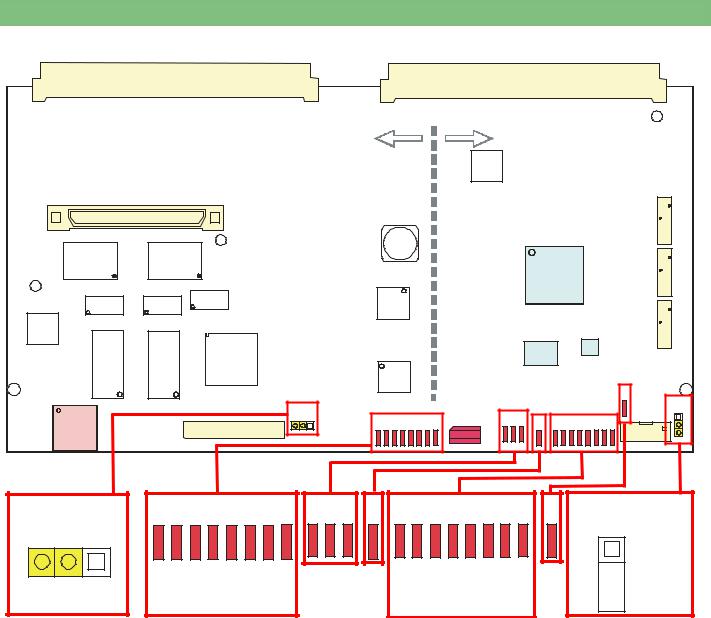
2.6Digital Board DB
P1 |
|
P2 |
|
|
|
|
|
Controller |
|
|
|
|
|
|
|
|
|
Supervisor |
|
|
||||||||||
|
|
|
|
|
|
|
|
|
|
|
|
U7 |
|
|
|
|
|
|
|
|
|
|
|
|
|
P4 |
|
|
|
|
|
|
|
|
|
|
|
|
|
|
|
|
|
|
|
|
|
|
P5 |
|
|
|
|
|
|
|
|
|
|
|
|
|
|
|
|
|
|
|
|
|
|
|
|
|
|
|
|
|
|
L33 |
|
|
|
|
|
|
|
|
|
|
|
|
|
|
|
|
|
|
|
U28 |
|
|
|
|
|
|
|
|
|
|
|
|
|
|
|
|
|
|
|
|
|
|
|
|
|
|
|
|
|
|
|
|
|
|
|
|
|
|
|
|
U30 |
|
|
|
|
|
|
P6 |
|
|
|
|
|
|
|
|
|
|
|
|
|
|
|
|
FPGA |
|
|
|
|
|
||||
|
|
U33 |
|
|
|
|
|
|
|
|
|
|
|
|
|
|
|
|
|
|
||||
U35 |
U36 |
|
U27 |
|
|
|
|
|
|
|
|
|
|
|
|
|
|
|
|
|
|
|||
|
|
|
|
|
|
|
|
|
|
|
|
|
|
|
|
|
|
|
|
|||||
|
|
|
|
|
|
|
|
|
|
|
|
|
|
|
|
|
|
|
|
|
|
|
||
U39 |
|
|
|
|
|
|
|
|
|
|
|
|
|
|
|
|
|
|
|
|
|
|
|
P7 |
|
|
|
|
|
|
|
|
|
|
|
|
|
|
|
|
|
|
|
|
|
|
|
|
|
|
|
|
|
|
|
|
|
|
|
|
|
|
|
|
U46 |
|
|
|
U45 |
|
|
|
||
U55 |
U56 |
U43 |
|
|
|
|
|
|
|
|
|
|
|
|
|
|
|
|
|
|
|
|
||
|
|
|
|
|
|
|
|
|
|
|
|
|
|
|
|
|
|
|
|
|
|
|||
|
|
|
|
|
|
|
|
|
|
|
|
|
|
|
|
|
|
|
|
|
|
|
||
|
|
|
|
U53 |
|
|
|
|
|
|
|
|
|
|
|
|
|
|
|
|
|
|
|
|
|
|
|
|
|
|
|
|
|
|
|
S1 |
|
|
|
|
|
|
|
|
|
|
|
|
D13 |
P11 |
|
JP1 |
|
|
|
|
|
|
|
|
D24 |
D25 |
D26 |
|
|
|
|
|
|
|
|
|
JP2 |
|
|
D16 |
D17 |
D18 |
D19 |
D20 |
D21 |
D22 |
D23 |
D27 |
D28 |
D29 |
D30 |
D31 |
D32 |
D33 |
D34 |
D35 |
P14 |
||||||
|
P13 |
|
|
|
|
|
|
|
|
|
|
|
|
|
|
|
|
|
|
|
|
|
||
JP1 |
D16 |
D17 |
D18 |
D19 |
D20 |
D21 |
D22 |
D23 |
D24 |
D25 |
D26 |
D27 |
D28 |
D29 |
D30 |
D31 |
D32 |
D33 |
D34 |
D35 |
D13 |
|
|
|
|
|
|
|
|
|
|
|
|
|
|
|
|
|
|
|
|
|
|
CWP |
01234567 |
|
|
|
|
0123456 |
7 |
|
|||||||||||||
Controller |
|
|
|
|
|
Supervisor |
|
|
|||||||||||||
Fig. : Digital Board DB (LLD) with Controller and Supervisor
JP2
 SWP
SWP
2.6.1Legend Digital Board
Calibration Data
All calibration data are stored on the digital board. The calibration data must be stored additionally on the compact flash card CFC.
12 Bit AD Converter
Both supervisor and controller have a 12 bit AD converter with a range of 0 to 4095.
P4/P5/P6/P7/P13/P14: not applicable
P11 USB Type A for SW installation with USB stick
Supervisor Sensors:
BICPOS, KPPOS, UFPOS
Controller/Supervisor Sensors:
BKUS, SBS1, SBS2, BPS_IMP, BPA_DIR, BPV_IMP, BPV_DIR
Pumps:
BPA, BPV, EP, FPA, FPE
Controller Sensors:
NSVB, BICSS, KSS, MSBK1/2, RDV, SAD, BPADS, BPVDS, BL (Controller/Supervisor Sensor Analog Board)
Jumper JP1:
Default: Controller Write Protect CWP (for controller firmware)
Controller LEDs D13 – D20:
Status 0 – 7 for installation of LLC software
FPGA LEDs V7 – V9: always ON Voltages for FPGA (U30) and periphery
(FPGA: Field Programmable Gate Array – configurable logical circuit)
LED V10: flashes permanently
Cycle time, system is running
Supervisor LEDs V11 – V18:
Status 0 – 7 for installation of LLS software
LED V5: always ON after loading
The content of the memory (U45) is loaded to FPGA (U30) during switch-on. The therapy program and the service program is stored in the RAM (U45).
Jumper JP2:
Default: Supervisor Write Protect SWP (for supervisor firmware)
S1 Service Switch:
Position 0: Therapy Mode
Position 2: TSM Service Program Mode
Position 3: Software Installation/Update Mode
BA-TE-DE08C M.KAY Dialog+ SW9xx_sm_Chapter 2_1-2010.doc/pdf <100329> yymmdd
B. Braun Avitum AG
|
2 . Technical System Description |
|
|
Dialog+ SW 9.xx |
1 / 2 0 1 0 |
2 - 11 |
|
|
|
|
|
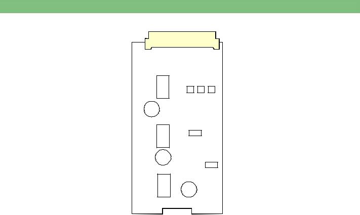
2.7Analog Board AB
P1 |
|
P2 |
|
|
|
|
|
|
|
|
|
|
|
|
|
|
|
|
|
|
|
|
|
U21 |
|
|
|
|
|
||
|
|
|
|
|
|
|
|
|
|
|
|
|
|
|
|
|
|
|
|
|
|
|
|
|
|
|
|
|
|
|
|
|
|
|
|
|
|
|
|
|
|
|
|
|
|
|
|
|
|
|
|
|
|
|
|
|
|
|
|
|
|
|
|
|
|
|
|
|
|
|
|
|
|
|
|
U28 |
|
|
|
|
|
|
|
|
|
|
|
|
|
|
|
|
|
|
|
U29 |
|
|
|
||||
|
|
|
|
|
|
|
|
|
|
|
|
|
|
|
|
|
|
|
|
|
|
|
|||
|
|
|
|
|
|
|
|
|
|
|
|
|
|
|
|
|
|
|
|
|
|
|
|
|
|
|
|
|
|
|
|
|
|
|
|
|
|
|
|
|
|
|
|
|
|
|
|
|
|
|
|
|
|
|
|
|
|
|
U32 |
|
|
|
|
|
|
|
|
|
|
|
|
|
|
|
|
|
|
|
|
|
|
|
|
|
|
|
|
|
|
|
|
|
|
|
|
U33 |
|
|
|
|
|
||
|
|
|
|
|
|
|
|
|
|
|
|
|
|
|
|
|
|
|
|
|
|||||
|
|
|
|
|
|
|
|
|
|
|
|
|
|
|
|
|
|
|
|
|
|
|
|
|
|
|
|
|
|
|
|
|
|
|
|
|
|
|
|
|
|
|
|
|
|
|
|
|
|
|
|
|
|
|
|
|
|
|
|
|
|
|
|
|
|
U39 |
|
|
|
|
|
|
|
|
|
||
|
|
|
|
|
|
|
|
|
|
|
|
|
|
|
|
|
U38 |
|
|
|
|
|
|||
U35 |
|
U36 |
|
U37 |
|
|
|
|
|
|
|
|
|
|
|
|
|
|
|
|
|
|
|
|
|
|
|
|
|
|
|
|
|
|
|
|
|
|
|
|
|
|
|
|
|
|
|
|
|||
|
|
|
|
|
|
|
U40 |
|
U42 |
|
|
|
|
U43 |
|
|
|
U44 |
|
|
U45 |
||||
|
|
|
|
|
|
|
|
|
|
|
|
|
|
|
|
|
|
|
|
|
|
|
|
|
|
|
|
|
|
|
|
|
|
|
|
|
|
|
|
|
|
|
|
|
|
|
|
|
|
|
|
|
|
|
|
|
|
|
|
|
|
|
|
|
|
|
|
|
|
|
|
|
|
|
|
|
|
|
|
|
|
|
|
|
U41 |
|
|
|
|
|
|
|
|
|
|
|
|
|
|
|
|
|
|
|
|
|
|
|
|
|
|
|
|
|
|
|
|
U47 |
|
|
|
U48 |
|
|
U49 |
||||
|
|
|
|
|
|
|
|
|
|
|
|
|
|
|
|
|
|
|
|
|
|||||
|
|
|
|
|
|
|
|
|
|
|
U46 |
|
|
|
|
|
|
|
|
|
|
|
|
|
|
|
|
|
|
|
|
|
|
|
|
|
|
|
|
|
|
|
|
|
|
|
|
|
|
|
|
|
|
|
|
|
|
|
|
|
|
|
|
|
|
|
|
|
|
|
U50 |
|
|
|
|
||
Fig. : Analog Board AB (LLA)
2.7.1Legend Analog Board
P1/P2
Controller Sensors:
PBS, TSHE, TSE, TSBIC, TSD, TSDE, BICLF, ENDLF, PE, LAFS
Supervisor Sensors:
TSD-S, ENDLF-S
Controller/Supervisor Sensors:
BL, PBE, PA, PV, PDA
BA-TE-DE08C M.KAY Dialog+ SW9xx_sm_Chapter 2_1-2010.doc/pdf <100329> yymmdd
B. Braun Avitum AG
|
2 . Technical System Description |
|
|
Dialog+ SW 9.xx |
1 / 2 0 1 0 |
2 - 12 |
|
|
|
|
|
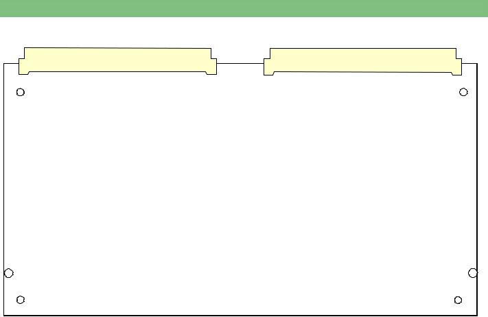
2.8HDF Online Board HOB
P1
U2
U5
P4
Fig. : HDF Online Board
2.8.1Legend HDF Online Board
P1: Sensors: PSABFS, PSAUS, PSPOSS, FEHDFS, FEDFFS |
P4: Valves VBE, VDFF, VSAA, VSAE, VSB |
BA-TE-DE08C M.KAY Dialog+ SW9xx_sm_Chapter 2_1-2010.doc/pdf <100329> yymmdd
B. Braun Avitum AG
|
2 . Technical System Description |
|
|
Dialog+ SW 9.xx |
1 / 2 0 1 0 |
2 - 13 |
|
|
|
|
|
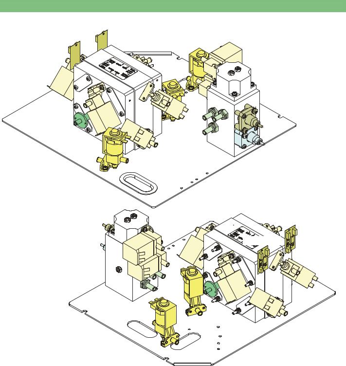
2.9UF Sub-Rack
MSBKB1/2
VDEBK1 |
VDA |
VLA |
|
|
|
|
VEBK1 |
|
|
|
LA |
VABK2 |
VBP |
DDE |
VDEBK2 |
VABK1 |
|
MSBK2 |
|
|
|
|
|
|
VDABK2 |
RVFPA |
|
|
|
VEBK2 |
|
|
DDE |
LA |
VABK1 |
VDEBK2 |
|
|
|
MSBKB1/2 |
RVFPA VLA |
|
|
VABK2 |
|
|
|
|
VBP |
|
|
VDEBK1 |
|
|
|
|
|
|
VEBK1 |
VDABK1 |
|
|
|
|
|
VDA |
|
|
Fig. : UF Sub-Rack
2.9.1 |
Legend UF Sub-Rack |
|
|
Balance Chamber BK1/2 |
Outlet Balance Chamber Valve VABK2 |
|
Bypass Valve VBP |
Outlet Dialyser Balance Chamber Valve VDABK1 |
|
Throttle Dialyser Inlet DDE |
Outlet Dialyser Balance Chamber Valve VDABK2 |
|
Air Separator LA |
Inlet Dialyser Balance Chamber Valve VDEBK1 |
|
Membrane Position Sensor Balance Chamber Board MSBKB1/2 |
Inlet Dialyser Balance Chamber Valve VDEBK2 |
|
Membrane Position Sensor Balance Chamber MSBK1/2 |
Inlet Balance Chamber Valve VEBK1 |
|
Non-Return Valve Outlet Flow Pump RVFPA |
Inlet Balance Chamber Valve VEBK2 |
|
Outlet Balance Chamber Valve VABK1 |
Air Separator Valve VLA |
BA-TE-DE08C M.KAY Dialog+ SW9xx_sm_Chapter 2_1-2010.doc/pdf <100329> yymmdd
B. Braun Avitum AG
|
2 . Technical System Description |
|
|
Dialog+ SW 9.xx |
1 / 2 0 1 0 |
2 - 14 |
|
|
|
|
|
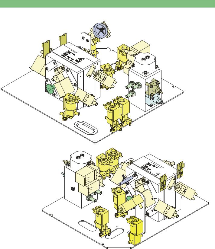
2.10UF Sub-Rack HDF Online
|
VBE |
|
|
MSBKB1/2 |
|
|
|
HFB |
VEBK2 |
|
|
|
|
|
|
VSB |
|
|
VLA |
VDEBK1 |
|
|
|
VEBK1 |
|
|
|
|
|
|
LA |
VABK2 |
|
VBP |
DDE |
VDEBK2 VDABK2 |
VABK1 |
|
|
MSBK2 |
|
|
|
RVFPA
VDA
VSAE
VSAA
|
VSAE |
|
|
|
VSAA |
|
VDEBK2 |
DDE |
LA |
VABK1 |
|
|
|
|
MSBKB1/2 |
RVFPA VLA |
HFB |
|
VABK2 |
|
|
||
VBP |
|
VBE |
VDEBK1 |
|
|
||
|
|
|
VEBK1 VDABK1
VDA |
VSB |
Fig. : UF Sub-Rack HDF Online
2.10.1 |
Legend UF Sub-Rack HDF Online |
|
|
Balance Chamber BK1/2 |
Outlet Dialyser Balance Chamber Valve VDABK1/2 |
|
Bypass Valve VBP |
Inlet Dialyser Balance Chamber Valve VDEBK1/2 |
|
Throttle Dialyser Inlet DDE |
Inlet Balance Chamber Valve VEBK1/2 |
|
Hydrophobic Vent Filter HFB |
Air Separator Valve VLA |
|
Air Separator LA |
Additional Components for HDF Online: |
|
Membrane Position Sensor Balance Chamber Board MSBKB1/2 |
Substitute Bypass Valve VSB |
|
Membrane Position Sensor Balance Chamber MSBK1/2 |
Substitute Connection Outlet Valve VSAA |
|
Non-Return Valve Outlet Flow Pump RVFPA |
Substitute Connection Inlet Valve VSAE |
|
Outlet Balance Chamber Valve VABK1/2 |
Filter Vent Valve VBE |
BA-TE-DE08C M.KAY Dialog+ SW9xx_sm_Chapter 2_1-2010.doc/pdf <100329> yymmdd
B. Braun Avitum AG

|
2 . Technical System Description |
|
|
Dialog+ SW 9.xx |
1 / 2 0 1 0 |
2 - 15 |
|
|
|
|
|
2.11DF Sub-Rack
A |
BICLF |
RVB |
|
|
BICP |
||
|
|
|
|
|
RVK |
UFP |
|
ENDLF |
|
TSDS |
KP |
|
|
|
|
FPE
FPA
RVFPE
RFUFP
KP
UFP
BICP
A
ENDLF
RVK
 BICLF
BICLF
RVB
TSBIC
FPE |
FPA |
TSD
Fig. : DF Sub-Rack
2.11.1 |
Legend DF Sub-Rack |
|
|
BIC Pump BICP |
Non-Return Valve Flow Pump Inlet RVFPE |
|
Degassing Pressure Sensor PE |
Non-Return Valve Concentrate RVK |
|
END Conductivity/Supervisor ENDLF/ENDLF-S |
Non-Return Valve UF Pump RFUFP |
|
Outlet Flow Pump FPA (Motor Cover A) |
Bicarbonate Temperature Sensor TSBIC |
|
Inlet Flow Pump FPE (Motor Cover A) |
Dialysate Temperature Sensor TSD |
|
Concentrate Pump KP |
Dialysate Supervisor Temperature Sensor TSD-S |
|
Bicarbonate Conductivity Sensor BICLF |
UF Pump UFP |
|
Bicarbonate Non-Return Valve RVB |
|
BA-TE-DE08C M.KAY Dialog+ SW9xx_sm_Chapter 2_1-2010.doc/pdf <100329> yymmdd
B. Braun Avitum AG
|
2 . Technical System Description |
|
|
Dialog+ SW 9.xx |
1 / 2 0 1 0 |
2 - 16 |
|
|
|
|
|
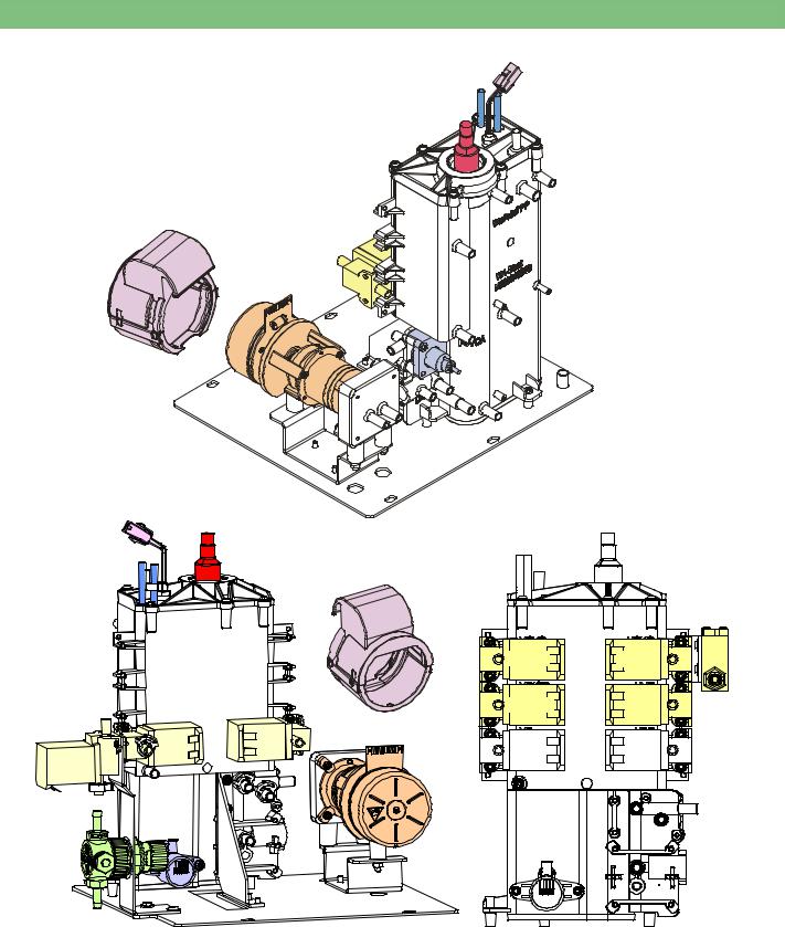
2.12Water Sub-Rack
NSVB
WT
H
WAB
A
VEB
EP |
RVDA |
NSVB |
H |
WT |
|
A
WA-Block
VVBE |
VZ VEB |
|
EP |
||
|
DMV PE
DBK
VBKS VBKO
VBICP VVB
VZ VEB
PE
Fig. : Water Sub-Rack Fig. : Water Block with Valves for BIC Option
2.12.1 |
Legend Water Sub-Rack |
|
|
Water Block WAB (with integrated Degassing Chamber EK, Upline Tank |
Upline Tank Inlet Valve VVBE |
|
VB and Heat Exchanger WT) |
Upline Tank VB |
|
Pressure Reducer DMV |
|
|
Degassing Pressure Sensor PE |
|
|
Degassing Chamber EK |
Additional Components for Option BIC Cartridge: |
|
Degassing Pump EP (Motor Cover A) |
Throttle BIC Cartridge Holder DBK |
|
Heater H |
BIC Concentrate Suction Rod Valve VBKS |
|
Degassing Temperature Sensor TSE |
Top BIC Cartridge Valve VBKS |
|
Heater Temperature Sensor TSH |
BIC Pump Valve VBICP |
|
Heater Inlet Temperature Sensor TSHE |
Upline Tank Valve VVB |
BA-TE-DE08C M.KAY Dialog+ SW9xx_sm_Chapter 2_1-2010.doc/pdf <100329> yymmdd
B. Braun Avitum AG
|
2 . Technical System Description |
|
|
Dialog+ SW 9.xx |
1 / 2 0 1 0 |
2 - 17 |
|
|
|
|
|
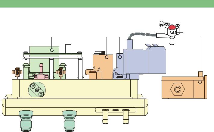
2.13Rinsing Bridge
1 |
2 |
3 |
4 |
5 |
VD |
|
|
TSDE |
|
|
PDA |
|
VDE |
|
BL
Fig. : Rinsing Bridge
2.13.1Legend Rinsing Bridge
1 |
Disinfection Valve VD |
4 |
Temperature Sensor Dialyser Inlet TSDE |
2 |
Pressure Sensor Dialysate Outlet PDA |
5 |
Blood Leak Detector BL |
3 |
Dialyser Inlet Valve VDE |
|
|
BA-TE-DE08C M.KAY Dialog+ SW9xx_sm_Chapter 2_1-2010.doc/pdf <100329> yymmdd
B. Braun Avitum AG
 Loading...