


 Loading...
Infusomat P
Service-Manual
Version 2.0 English
Software: IFPC02001
IFPC02002
IFPe02003
IFPE13002
IFPE13003

0
This Service-Manual is valid for
The complete Service-Manual contains the following pages:
Voltage 230 V: |
Ord. No. |
Infusomat P, German . . . . . . . . . . . . . . . . . . . . . . . . . . . . 871 2174
Infusomat P, French . . . . . . . . . . . . . . . . . . . . . . . . . . . . . 871 2182
Infusomat P, Dutch. . . . . . . . . . . . . . . . . . . . . . . . . . . . . . 871 2190
Infusomat P, Italian . . . . . . . . . . . . . . . . . . . . . . . . . . . . . 871 2204
Infusomat P, Danish . . . . . . . . . . . . . . . . . . . . . . . . . . . . . 871 2298
Infusomat P, Norwegian . . . . . . . . . . . . . . . . . . . . . . . . . 871 2301
Infusomat P, Swedish. . . . . . . . . . . . . . . . . . . . . . . . . . . . 871 2310
Infusomat P, Finnish. . . . . . . . . . . . . . . . . . . . . . . . . . . . . 871 2336
Infusomat P, Czech. . . . . . . . . . . . . . . . . . . . . . . . . . . . . . 871 2344
Infusomat P, Polish. . . . . . . . . . . . . . . . . . . . . . . . . . . . . . 871 2352
Voltages 200 V / 230 V / 240 V, switchable:
Infusomat P, English. . . . . . . . . . . . . . . . . . . . . . . . . . . . . 871 2212
Infusomat P, English. . . . . . . . . . . . . . . . . . . . . . . . . . . . . 871 2379
Infusomat P, Spanish . . . . . . . . . . . . . . . . . . . . . . . . . . . . 871 2263
Infusomat P, Portuguese . . . . . . . . . . . . . . . . . . . . . . . . . 871 2271
Infusomat P, Turkish. . . . . . . . . . . . . . . . . . . . . . . . . . . . . 871 2280
Voltages 100 V / 110 V / 120 V, switchable:
Infusomat P, English. . . . . . . . . . . . . . . . . . . . . . . . . . . . . 871 2387
Infusomat P, Dutch. . . . . . . . . . . . . . . . . . . . . . . . . . . . . . 871 2395
Infusomat P, Spanish . . . . . . . . . . . . . . . . . . . . . . . . . . . . 871 2409
Infusomat P, Portuguese . . . . . . . . . . . . . . . . . . . . . . . . . 871 2417
Page 0-1 to Page 0-8
Page 1-1 to Page 1-10
Page 2-1 to Page 2-6
Page 3-1 to Page 3-12
Page 4-1 to Page 4-20
Page 5-1 to Page 5-2
Page 6-1 to Page 6-2
Page 7-1 to Page 7-2
Page 8-1 to Page 8-6
Page 9-1 to Page 9-2
Page 10-1 to Page 10-4
Page A-1 to Page A-4
0 - 2 |
Infusomat P 2.0gb |

Table of Contents 0
Important Information on this Manual |
Service Work |
Page |
0 - 5 |
|
Technical Safety Inspections |
Page |
0 - 5 |
|
Current Versions |
Page |
0 - 5 |
|
Revision Service |
Page |
0 - 5 |
|
Non-Liability |
Page |
0 - 5 |
|
ISO 9000 ff/EN 46 000 ff |
Page |
0 - 6 |
|
Repair and Inspection only |
|
|
|
by Trained Technicians |
Page |
0 - 6 |
|
Spare Parts and Test Equipment |
Page |
0 - 6 |
|
Setting Off |
Page |
0 - 6 |
General Information |
Technical Training |
Page |
0 - 7 |
|
Entry for the Product Training |
Page |
0 - 7 |
|
Ordering of Spare Parts and Test Equipment |
Page |
0 - 7 |
|
Return of Spare Parts |
Page |
0 - 7 |
|
Service Hotline |
Page |
0 - 7 |
|
Safety Officer |
Page |
0 - 7 |
|
Translation |
Page |
0 - 7 |
System Overview |
Design |
Page |
1 - 1 |
|
Operation Flow Chart |
Page |
1 - 2 |
|
Function |
Page |
1 - 3 |
|
Voltage Supply |
Page |
1 - 4 |
|
Signal Table |
Page |
1 - 5 |
|
Mains Operation |
Page |
1 - 6 |
|
Battery Operation |
Page |
1 - 7 |
|
Alarm Circuit |
Page |
1 - 7 |
|
Pump Unit |
Page |
1 - 7 |
|
Computer Interface |
Page |
1 - 8 |
|
Braun fluid manager system (fm system) |
Page |
1 - 9 |
|
Internal Assignment |
Page |
1 - 9 |
|
Accessories |
Page |
1 - 10 |
Software |
Software Update |
Page |
2 - 1 |
|
Approved Software Versions |
Page |
2 - 2 |
|
Error Messages and Alarms |
Page |
2 - 3 |
|
Software Default Values |
Page |
2 - 5 |
Service Program |
Structure of the Service Program |
Page |
3 - 1 |
|
Additional Functions with |
|
|
|
Inserted Service Plug |
Page |
3 - 2 |
|
Start / Quit the Service Program |
Page |
3 - 3 |
|
Unit Data |
Page |
3 - 3 |
|
History Data |
Page |
3 - 5 |
|
Test |
Page |
3 - 6 |
|
Unit Modifications |
Page |
3 - 7 |
|
Calibration |
Page |
3 - 10 |
Unit Elements |
Mains Fuses |
Page |
4 - 1 |
|
Battery |
Page |
4 - 1 |
|
Door Lock |
Page |
4 - 2 |
|
Pump Cover |
Page |
4 - 3 |
|
Pump Housing |
Page |
4 - 4 |
|
Housing and Handle |
Page |
4 - 5 |
Infusomat P 2.0gb |
|
|
0 - 3 |
0 |
Table of Contents |
|
|
|
Controller Board |
Page |
4 |
- 6 |
|
Rear Panel |
Page |
4 |
- 8 |
|
Front Panel |
Page |
4 - 11 |
|
|
Pump Unit |
Page |
4 - 13 |
|
|
Occlusion Sensor |
Page |
4 - 15 |
|
|
Air Sensor |
Page |
4 - 18 |
|
|
Operating Unit |
Page |
4 - 19 |
|
|
Barcode Label |
Page |
4 - 20 |
|
|
Frame with Seal |
Page |
4 - 20 |
|
Checks after Repair |
|
Page |
5 |
- 1 |
Maintenance |
|
Page |
6 |
- 1 |
Technical Safety Inspection TSI |
|
Page |
7 |
- 1 |
Procedural Instructions for Inspection |
1. Visual Inspection |
Page |
8 |
- 1 |
|
2. Electrical Safety Inspection as |
|
|
|
|
per IEC/EN60 601-1 |
Page |
8 |
- 1 |
|
3. Functional Inspection |
Page |
8 |
- 2 |
|
4. Pump Unit Inspection |
Page |
8 |
- 3 |
Test Equipment and Special Tools |
Test Equipment and Special Tools |
Page |
9 |
- 1 |
Spare Parts List |
Unit Elements |
Page |
10 |
- 1 |
|
Colours |
Page |
10 |
- 2 |
|
Miscellaneous |
Page |
10 |
- 2 |
|
Accessories |
Page |
10 |
- 3 |
|
Software Update |
Page |
10 |
- 3 |
Appendix |
ESD Recommendations |
Page |
A - 1 |
|
|
Workstation |
Page |
A - 1 |
|
|
Revision Service-Documentation |
Page |
A - 2 |
|
|
Current Information |
Page |
A - 2 |
|
|
Order Form |
Page |
A - 2 |
|
0 - 4 |
Infusomat P 2.0gb |

Important Information on this Manual 0
The following notes should be observed: |
|
Service Work |
The present manual is for your information only. The possession of |
|
this manual does not authorize the performance of service work. |
|
Service tasks may only be executed by persons, who |
|
- have received appropriate training on the system from B. |
|
Braun |
|
- are included in the revision service |
|
- possess the necessary test equipment and mechanical aids, |
|
and |
|
- fulfil the personal requirements (training and knowledge). |
Technical Safety Inspections |
B. Braun also recommends training on the technical safety in- |
|
spections, or to perform at least the steps indicated in the current |
|
version of the manual, as: |
|
- the TSI requires that the instructions in the manuals are ob- |
|
served |
|
- the manuals are a reference for measurements |
|
- depending on the unit type, the service program must be |
|
called up which may lead to a dangerous unit condition in the |
|
case of an inappropriate operation. Furthermore, a special |
|
service connector may be necessary. |
Current Versions |
This manual version corresponds to the state when the manual |
|
was written. Technical changes, especially software modifications |
|
must always be expected. The state of the revision is indicated by |
|
the index number on the title page. |
Revision Service |
The possession of this manual does not automatically mean inclu- |
|
sion in the revision service. You will be included in the revision |
|
service after: |
|
- technical training by B. Braun Melsungen or |
|
- a written order placed with the sales department of B. Braun |
|
(incurred costs). |
Non-Liability |
B. Braun Melsungen AG does not assume any responsibility for in- |
|
juries to persons, property damages or other damages caused by: |
|
- the use of a wrong manual, or a manual which does not cor- |
|
respond to the revision state for maintenance, repair, and |
|
service tasks |
|
- the non-inclusion of the service technician in the revision |
|
service |
|
- technicians who have not participated in a technical training |
|
course for the specific B. Braun unit. |
Infusomat P 2.0gb |
0 - 5 |

0 |
Important Information on this Manual |
|
|
ISO 9000 ff/EN 46 000 ff |
B. Braun is certified in accordance with DIN ISO 9001 and DIN EN |
|
|
46 001. This certification also includes maintenance and service. |
|
|
The Infusomat P complies with the IEC/EN60601-1 and |
|
|
IEC/EN60601-2-24 standards and is certified with the CE label ac- |
|
|
cording to the EC directive 93/42/EC. |
|
Repair and Inspection only |
Training may only be performed by B. Braun. The possession of the |
|
by Trained Technicians |
manual does not authorize the performance of repairs. The in- |
|
|
structions on electrostatic sensitive components (ESD standards) |
|
|
must be observed. |
|
|
An electrical check must be performed following each repair (see |
|
|
„Checks after Repair“ pg. 5 - 1). |
|
Spare Parts and Test Equipment |
Only use original spare parts from the manufacturer. Do not |
|
|
tamper with assembly groups which can only be exchanged com- |
|
|
pletely. The spare parts required are listed in the repair instruc- |
|
|
tions. |
|
|
The inspection personnel is responsible for the calibration of the |
|
|
test equipment. Original test equipment can be calibrated at the |
|
|
works of B. Braun. Further information is available upon request. |
|
Setting Off |
Additional notes and warnings are set off as follows: |
|
|
|
|
|
Note |
|
|
Gives additional or special notes on information and working |
|
|
steps. |
|
|
|
|
|
|
|
|
CAUTION |
|
|
Is used for working steps which may result in damage to the unit, |
|
|
system or to a connected device. |
|
|
|
|
|
|
|
|
WARNING |
|
|
IS USED FOR WORKING STEPS WHICH MAY RESULT IN PERSONAL |
|
|
INJURY. |
|
|
|
|
0 - 6 |
Infusomat P 2.0gb |

General Information 0
Technical Training |
B. Braun Melsungen AG |
|
|
|
Stadtwald Haus 6 |
|
|
|
D-34 212 Melsungen |
|
|
|
Germany |
|
|
|
Responsibility |
|
|
|
Dieter Gundlach |
Tel.: |
+49 5661 71 - 37 74 |
|
|
Fax: |
+49 5661 71 - 28 81 |
Entry for the Product Training |
Only via the responsible representative |
|
|
Ordering of Spare Parts and Test Equipment |
B. Braun Melsungen AG |
|
|
|
P.O. Box 11 20 |
|
|
|
D-34209 Melsungen |
|
|
|
Germany |
|
|
|
Hospitals and Suppliers |
Tel.: |
+49 800 2 27 28 24 |
|
of Hospitals |
Fax: |
+49 5661 71 37 98 |
|
Dealer and |
Tel.: |
+49 5661 71 36 28/29 |
|
Medical Houses |
Fax: |
+49 5661 71 35 50 |
Return of Spare Parts |
B. Braun Melsungen AG |
|
|
|
Schwarzenberger Weg 73-79 |
|
|
|
Wareneingang Werk C |
|
|
|
D-34 212 Melsungen |
|
|
|
Germany |
|
|
Service Hotline |
Mr. Tippel, Mr. Clobes |
|
|
|
Tel.: +49 56 61 71 - 35 25 |
|
|
|
Fax: +49 56 61 71 - 35 26 |
|
|
|
E-Mail: karl.tippel@bbraun.com |
|
|
|
E-Mail: christian.clobes@bbraun.com |
|
|
Safety Officer |
Dr. Wilhelm Wucherpfennig |
|
|
|
Fax: +49 56 61 71 - 46 36 |
|
|
|
E-Mail: wilhelm.wucherpfennig@bbraun.com |
||
Translation |
Brückner GmbH, Germany |
|
|
Infusomat P 2.0gb |
0 - 7 |

0 |
General Information |
|
|
For your notes:
0 - 8 |
Infusomat P 2.0gb |

System Overview 1
Design |
The Infusomat P is a compact volumetric peristaltic infusion |
|
pump. |
|
Standard delivery rate range 0.1 to 999.9 ml/h |
|
The unit is operated via a membrane keypad. It is equipped with |
|
an LCD (liquid crystal display) for the display of the delivery rate |
|
and the operating support of the user. Two control LEDs display |
|
alarms, and the running of the infusion pump. |
Guide for Short Pole Clamp |
Drop Sensor |
Peristaltic Pump |
|
|
|
||
Handle |
|
Flow Inhibitor |
|
|
|
|
|
|
|
MFC-Socket |
|
Door Lock |
|
|
|
LCD Display |
|
|
|
Softkeys |
Optical |
|
|
|
|
|
|
|
Interface |
|
|
Keypad |
fm Recessed Plug |
|
|
Potential Equalization |
|
||
|
|
||
|
Bolt |
|
Air Sensor |
|
Drop Sensor Socket |
|
|
Barcode Label |
|
IP 003 |
|
|
|
||
Mains Connection |
|
|
|
Control LEDs |
|
|
|
Fig.: 1 - 1 Unit Design Infusomat P |
|
|
|
A barcode label is attached to the left front side of new Infusomat P unit versions which can be retrofitted on previous devices. This barcode label is used to read the serial and DIANET type number via a scanner when the Infusomat P is operated in an fm-system.
Infusomat P 2.0gb |
1 - 1 |

1 |
System Overview |
|
|
Operation Flow Chart
Switch On
Tube Selection 5
|
|
|
|
|
Standard Operation |
|
|
Service Plug, |
|
Special Functions ... 3 |
|
|||||||
|
|
|
|
|
|
|
Inserted ... 1 |
|
|
|||||||||
|
|
|
|
|
|
|
|
|
|
|
|
|
|
|
|
|||
|
|
|
|
|
|
|
|
|
|
|
|
|
|
|
|
|
|
|
|
|
|
|
|
|
|
|
|
|
|
|
|
|
|
|
|
||
|
|
|
|
|
|
|
|
|
|
|
|
|
|
- |
Dose Calculation 5 |
|||
|
|
|
|
|
|
|
|
|
|
|
|
|
|
- |
Bolus Function |
|||
Set Delivery Rate |
|
|
|
Preselected Volume |
|
|
Preselected Time |
- |
Standby Function |
|||||||||
|
|
|
|
|
|
|
|
|
|
|||||||||
|
|
|
|
|
|
|
|
|
|
|
|
|
|
- |
Drug Change |
|||
|
|
|
|
|
|
|
|
|
|
|
|
|
|
|
|
CC Mode 4 |
||
|
|
|
|
|
|
|
|
|
|
|
|
|
|
- |
||||
|
|
|
|
|
|
|
|
|
|
|
|
|
|
- |
Occlusion Pressure |
|||
|
|
|
|
|
|
|
|
Rate Calculation |
|
|
- |
Drop Control |
||||||
|
|
|
|
|
|
|
|
|
|
|
|
|
Piggyback 5 |
|||||
|
|
|
|
|
|
|
|
|
|
|
|
|
|
- |
||||
|
|
|
|
|
|
|
|
|
|
|
|
|
|
|||||
Start Infusion |
|
|
|
|
|
|
|
|
|
|
|
|
- |
Battery Capacity |
||||
|
|
|
|
|
|
|
|
|
|
|
|
|
|
|
|
|
||
|
|
|
|
|
|
|
|
|
|
|
|
|
|
- |
Data Lock |
|||
|
|
|
|
|
|
|
|
|
|
|
|
|
|
- |
Alarm Tone 6 |
|||
|
|
|
|
|
|
|
|
|
|
|
|
|
|
|||||
|
|
Stop Infusion |
|
|
|
|
|
|
|
|||||||||
|
|
|
|
|
|
|
|
|
- |
Contrast Setting |
||||||||
|
|
|
|
|
|
|
|
|
|
|
|
|
|
- |
Clock 5 |
|||
|
|
|
|
|
|
|
|
Change Delivery Rate |
|
|||||||||
|
|
|
|
|
|
|
|
|
||||||||||
|
|
|
|
|
|
|
|
|
|
|
|
|
|
|||||
|
|
|
|
|
|
|
|
|
|
|
|
|
|
|
|
|
|
|
Recall Info
1 See service program diagram
2 Only when preselected time or preselected volume has expired
3 Please pay attention to the activation in service program
Call up Bolus
4 Only available with IFPC
5 From software IFPe, IFPE
6 From software IFPE
KOR Mode 2
Fig.: 1 - 2
See Instructions for Use for detailed information.
1 - 2 |
Infusomat P 2.0gb |
System Overview |
1 |
|
|
Function |
Two independent software-controlled microprocessor systems |
|
control and monitor the hardware. On the basis of their functions, |
|
they are defined respectively as a control and a function proces- |
|
sor. Both systems work with independent clock frequencies and |
|
have access to different program and data memories. All safety- |
|
relevant functions are handled by both processors and the results |
|
are counter checked (CFand FC-latch). |
The input via the keypad is fed to both processors. Additionally the acknowledgement signal of the ON/OFF key is fed to the mains power supply logic (voltage E/A-TAS). The function processor has also access to this logic via E/A-INT.
Description |
of |
the |
voltage |
signals |
(see |
„Signal |
Table“ |
|
pg. 1 - 5). |
|
|
|
|
|
|
|
|
Fig.: 1 - 3 |
|
|
|
|
|
|
|
|
Infusomat P 2.0gb |
1 - 3 |
1 |
System Overview |
|
|
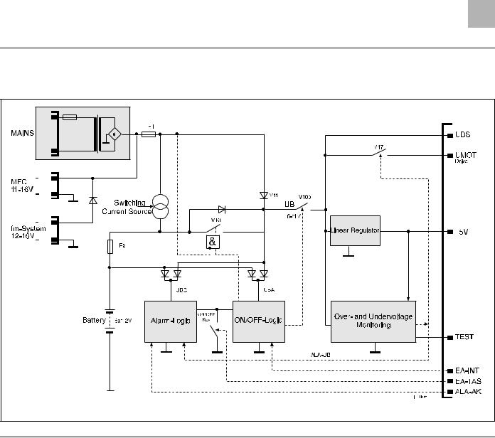
Voltage Supply |
The voltage supply is generated either directly from mains, via the |
|
FM plug (14 V connection to the fluid manager system), or via the |
|
MFC connector (11 to 16 V) and as an internal supply via the in- |
|
ternal 7.2 V NiCD battery. The mains module is available in three |
|
versions: 230 V, 220 / 230 / 240 V and 100 / 110 / 120 V. The rated |
|
voltage has a tolerance of + 10% to – 15 %. |
|
A voltage of 11 V to 18 V is available after transformation and rec- |
|
tification. This voltage is fed to the battery charge circuit and the |
|
unit supply. This is also valid for an external 12 V supply from the |
|
MFC or FM plug. The FET V10 switches between the external and |
|
the internal voltage supply. The transistor V10b works as an ON/ |
|
OFF switch for the operating voltages UBS, UMOT and +5V. The |
|
+5V supplies the complete electronics including the double chan- |
|
nel microprocessor system. A window comparator constantly |
|
monitors the +5V for undervoltage or overvoltage. The function is |
|
checked during switch-on. The operating voltage UBS supplies the |
|
stepper motor and the UMOT, the stepper motor drive. |
|
The transistor V47 switches the operating voltage UMOT. In case |
|
of an alarm the motor is switched off by V47. Additionally the |
|
switching function of the transistor is checked during the switch- |
|
on test. |
|
The circuit has two separate assembly groups with separate sup- |
|
ply voltages UBA and UBB. The ON/OFF circuit has a retriggerable |
|
delay switch-off. A follow-up charging circuit drives the transis- |
|
tor V10b. |
|
The alarm logic (operating voltage UBB) is an RS latch. This is set |
|
when the unit is running and activates the alarm circuit. The |
|
alarm buzzer and drive are also driven by UBB. The ON/OFF circuit |
|
is activated and the voltage supply is switched on by pressing the |
|
ON/OFF key. The alarm latch is reset simultaneously. A function |
|
test of the voltage monitoring, motor circuit and alarm activation |
|
is performed. The voltage supply is maintained by cyclic self-hold- |
|
ing pulses fed to the logic. The alarm latch is also activated. |
1 - 4 |
Infusomat P 2.0gb |
System Overview |
1 |
Fig.: 1 - 4 |
|
Signal Table |
|
|
|
|
Signal |
Meaning |
|
Signal |
Meaning |
|
||||
|
|
|
|
|
+5V |
Voltage Supply Electronic |
|
PKS2 |
Pump Head Sensor 2 |
5V-HT |
Overvoltage Test |
|
PKSS |
Pump Head Sensor Control |
5V-LT |
Undervoltage Test |
|
PRS |
Staff Call Relay Control |
AK-I |
Battery Charge and Discharge Current |
|
PRS-F |
Staff Call Relay Function Channel |
AK-LAD |
Battery Capacity ON/OFF |
|
PKSS |
Pump Head Sensor Control |
AK-Test |
Battery Test |
|
PRS.RUF |
Staff Call Relay Control |
ALA-UB |
Operating Voltage Alarm |
|
RDE |
Rate Display Enable |
CS |
Chip Select |
|
RES |
Power on Reset |
DI |
Data Input |
|
RES-F |
Reset Function Channel |
DO |
Data Output |
|
RES-K |
Reset Control Channel |
E/A-INT |
ON/OFF by Microprocessor |
|
RTS |
Return to Send (DIANET) |
E/A-ST |
ON/OFF Status |
|
Rx |
Receive Data |
Table 1 - 1 |
Signal Table (Part 1 of 2) |
|
|
|
|
|
|
||
Infusomat P 2.0gb |
|
|
1 - 5 |
|

1 |
System Overview |
|
|
Signal |
Meaning |
Signal |
Meaning |
|
|
|
|
E/A-TAS |
ON/OFF Key |
SCK |
Serial Data Lock |
EDB |
Electronic Occlusion Pressure |
TD-A0 |
Text Display Address 0 |
FMC-F |
FM Connection Function Channel |
TD-A1 |
Text Display Address 1 |
FMC-K |
FM Connection Control Channel |
TD-A2 |
Text Display Address 2 |
UEXT-N |
External 12V Supply (-) |
TD-A3 |
Text Display Address 3 |
UEXT-P |
External 12V Supply (+) |
TD-E |
Text Display Enable |
UFM-P |
External 12V Supply (FM) |
TD-R/W |
Text Display Read/Write |
LFCL |
Air Sensor Clock |
TD4 |
Text Display Data 4 |
LFDA |
Air Sensor Data |
TD5 |
Text Display Data 5 |
LFS |
Air Sensor Signal |
TD6 |
Text Display Data 6 |
LFSEL |
Air Sensor Selection |
TD7 |
Text Display Data 7 |
LFT |
Air Sensor Reset |
TSA |
Drop Sensor Output |
MISO |
Serial Data Output Interface |
TSCL |
Drop Sensor Clock |
MOSI |
Serial Data Input Interface |
TSE |
Drop Sensor Receiver |
MOTEIN |
Motor ON |
TSR |
Drop Sensor Regulation |
MS |
Motor Control |
TSS |
Drop Sensor Control |
P-ENA |
Port Enable |
Tx |
Transmit Data |
PH0 |
Phase 0 |
UBA, UBB |
Supply Voltage for Alarm, On/Off Logic, RTC |
PH1 |
Phase 1 |
UBS |
Switched Operating Voltage UB |
PH2 |
Phase 2 |
UBS-M |
UBS Measurement Line |
PH3 |
Phase 3 |
UMOT |
Supply Voltage of Motor Drive |
PKS |
Pump Cover Sensor |
UMOT-M |
UMOT Measurement Line |
PKS1 |
Pump Head Sensor 1 |
URTC |
Supply Voltage Clock Module |
Table 1 - 1 |
Signal Table (Part 2 of 2) |
|
|
|
|
||
|
|
||
Mains Operation |
When the unit is connected to mains the unit supply voltage is |
||
|
|
switched on for the duration of the switch-off delay time. If the |
|
|
|
microprocessor recognizes a sufficient mains voltage for the |
|
|
|
charging, the voltage supply is maintained. In this case only a bat- |
|
|
|
tery balance is carried out, because a key was not pressed. The ac- |
|
|
|
tual battery capacity and the battery operting hours are displayed |
|
|
|
in the LCD. The unit is switched off when the ON/OFF key is |
|
|
|
pressed for at least 2 seconds. Thereby the self-holding is trig- |
|
|
|
gered and the alarm latch is reset with a delay. After another 20 |
|
|
|
seconds the unit is switched off, because the pulses are missing. |
|
|
|
If the Infusomat P is switched off in mains operation with the ON/ |
|
|
|
OFF key, the internal mains voltage is still present. |
|
|
|
In mains operation the battery function is checked during the |
|
|
|
switch-on test. Therefor the charge and discharge current is |
|
1 - 6 |
|
|
Infusomat P 2.0gb |

System Overview |
1 |
|
|
|
measured and the charging of the battery is interrupted for the |
|
duration of the measurement. |
|
|
Battery Operation |
The battery function is monitored by the following data: charge |
|
current, discharge current and time, and self-discharge time. In |
|
battery operation the battery function is checked during the |
|
switch-on test. The theoretical load condition is read from the |
|
clock module of the battery. Then the battery is connected to UBS |
|
and the voltage is measured. If the minimum requirements are not |
|
reached a battery alarm is activated. |
|
|
Alarm Circuit |
The alarm generation consists of: |
|
- Standstill of pump due to switch-off of MS (motor circuit) |
|
and UMOT (motor operating voltage) |
|
- Audible alarm due to the drive of the buzzer or the loud- |
|
speaker via ALA-AK (control channel) or via ALA-UB |
|
- Optical alarm. Is displayed in the LCD and a separate LED dis- |
|
play. Additionally the set rate flashes with AAA.A. |
|
- Staff call via the MFC staff call cable. |
|
The user must check the optical and audible alarm during the |
|
switch-on test. An alarm must be activated to test the staff call |
|
alarm of the Infusomat P, e.g. open pump cover during operation. |
|
|
Pump Unit |
The pump head is driven by a stepper motor. Each full step of the |
|
motor is realized by 5 microsteps. The motor is driven by an FET |
|
output stage. The function processor controls the motor with the |
|
MS signal. A slot disc which is mounted on the pump head axle is |
|
scanned by two light barriers (PKS1 and PKS2 signal). Thereby the |
|
control microprocessor monitors the direction of rotation and |
|
speed of the pump head. |
|
The pump head position is also determined with the PKS2 signal. |
|
The motor can therefore be accelerated during the withdrawal |
|
phase. Thus a nearly pluse-free flow is realized in the lower deliv- |
|
ery range (<100 ml/h). The total pump head cycles and running |
|
time are available in the service program under history data. |
Infusomat P 2.0gb |
1 - 7 |

1 |
System Overview |
|
|
Mechanical Occlusion Pressure:
The Infusomat P has a linear peristaltic pump. This pump has 12 slides which are driven by a camshaft.
When the pump cover is closed, the pump tube is squeezed (occlusion) by at least one of the slides, independent of the pump head position. The complete pump unit is mounted behind the front panel in the cabinet frame. The hinges and the locking bow for the pump cover are led through the front panel. The pump cover is automatically closed when the operating unit door is closed. The slides are pressed against the pump cover by a spring system in the pump unit. Thereby a delivery pressure is realized and mechanically limited by the springs.
If the pressure limit is exceeded there is no volume delivery. The drop sensor activates an alarm. If one of the springs fails, the spring system will ensure that an unsafe condition cannot occur (free flow). The two remaining springs ensure an appropriately high occlusion pressure.
Electronic Occlusion Pressure:
The electronic occlusion sensor is mounted on the output side of the pump. A spring pressure loaded slide is seated on the infusion line. An increase of pressure in the infusion line leads to a deflection of the coil core via the pressure slide. The depth of immersion is measured inductively. When a preset pressure threshold is reached the pump drive is switched off, and an alarm is activated. The electronic occlusion pressure is a single channel circuit. In case of a failure, the mechanically limited maximum pressure can be reached.
|
Motor Switch-Off by Both Processors: |
|
Function processor: MS signal to switch-off the motor drive. - |
|
Control processor: MOTEIN signal to switch-off the drive of the |
|
motor operating voltage. |
|
|
Computer Interface |
The Infusomat P is equipped with a computer interface. It can be |
|
connected to the optical interface or via the MFC service plug. To |
|
activate the computer operation please ask for a detailed descrip- |
|
tion from B. Braun. |
|
Until software version IFPC: DIANET |
|
From software version IFPe, IFPE DianetStar |
1 - 8 |
Infusomat P 2.0gb |
System Overview |
1 |
|
|
Braun fluid manager system (fm system)
The Infusomat P can be operated as a stand-alone unit or integrated in an intensive care unit, e.g. the B. Braun fluid manager system (fm system). It is integrated by simply snapping the unit into the system.
Mains supply and data communication are automatically connected. Thereby data acquisition and transmission to higher computer system levels are possible.
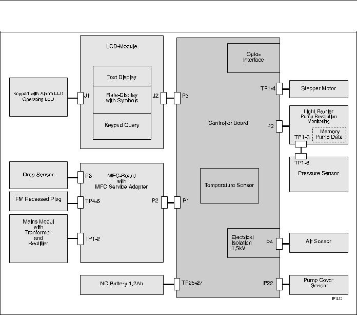
Internal Assignment
Fig.: 1 - 5 |
|
|
Infusomat P 2.0gb |
1 - |
9 |
1 |
System Overview |
|
|
Accessories |
General |
|
|
Designation |
Ord. No. |
|
Mounting clip for drop chamber ”TK 2000” . . . . . . . . |
3477 3223 |
|
Mounting clip for drop chamber ”Intrafix P” . . . . . . . |
3477 3215 |
|
Universal adapter for drop sensor . . . . . . . . . . . . . . . . |
0871 1747 |
|
Drop sensor, complete . . . . . . . . . . . . . . . . . . . . . . . . . . |
3450 578A |
|
Short infusion pole. . . . . . . . . . . . . . . . . . . . . . . . . . . . . |
0870 1644 |
|
Drop chamber holder . . . . . . . . . . . . . . . . . . . . . . . . . . . |
3477 3088 |
|
Mains lead (200-240V~) . . . . . . . . . . . . . . . . . . . . . . . . |
3450 2718 |
|
Mains lead (100-120V~) . . . . . . . . . . . . . . . . . . . . . . . . |
3450 5423 |
|
Mains lead USA / CAN . . . . . . . . . . . . . . . . . . . . . . . . . . |
3450 5393 |
Universal Clamp
Universal clamp, complete. . . . . . . . . . . . . . . . . . . . . . . 3450 5857
Pole Clamp (rotating) . . . . . . . . . . . . . . . . . . . . . . . . . . 0871 8482
1 - 10 |
Infusomat P 2.0gb |

Software 2
Software Update
Position |
1 |
2 |
3 |
|
4 |
|
5 |
6 |
|
7 |
8 |
9 |
|
|
Digit |
|
I |
F |
P |
E |
1 |
3 |
|
0 |
0 |
3 |
|
||
|
|
|
|
|
|
|
|
|
|
|
|
|
|
|
|
|
|
|
|
|
|
|
|
|
|
Revision Level |
|||
|
|
|
|
|
|
|
|
|
|
|
|
|||
|
|
|
|
|
|
|
|
Hardware Identification |
||||||
|
|
|
|
|
|
Software Group |
|
|
||||||
|
|
|
|
|
|
|
|
|
|
|
|
|
||
|
|
Infusomat P |
|
|
|
|
|
|
|
|||||
Fig.: 2 - 1 |
Coding |
|
|
|
|
|
|
|
|
|
|
|
|
|
|
|
|
|
|
|
|
|
|
|
|
|
|
|
|
Designation |
Ord. No. |
Update-Kit IFPC02002 . . . . . . . . . . . . . . . . . . . . . . . . . 3450 6462
Update-Kit IFPe02003 . . . . . . . . . . . . . . . . . . . . . . . . . . On request
Update-Kit IFPE13003 . . . . . . . . . . . . . . . . . . . . . . . . . On request (only units with controller
board with loudspeaker)
MFC interface line . . . . . . . . . . . . . . . . . . . . . . . . . . . . . .0871 1661
The higher digit always replaces the lower digit for the revision level, e.g. IFPE13003 replaces IFPE13002.
When the software group changes (IFPE13002) the unit functions are changed, too. Therefore unit users must be informed (e.g. instruct the user and exchange the instructions for use – software coding, e.g. IFPE is on the cover page of the instructions for use.)
Note
Mark the unit after having updated the software! The new software version must be clearly recognizable.
Only update from old to new software versions, never in reverse order (e.g. never update from IFPC02002 to IFPC02001!).
All units used in one ward should have the same software status and basic setup to avoid operator mistakes.
Note
Software updates must be reported to B. Braun for registration.
Observe the notes of the update program and the supplements!
Infusomat P 2.0gb |
2 - 1 |

2 Software
Approved Software Versions |
IFPC02001 |
|
- Basic software |
|
(Must not be used any more. Please contact the Technical |
|
Service of B. Braun). |
IFPC02002
- No optical staff call after power up (fluid manager system) - Optimized air sensor evaluation
- Manual bolus volume limited to 99.9 ml - Optimized special bolus function
IFPe02003
- Preselected volume and time counted down to 0 - Long-time compensation of delivery rate
- Interface changed to DIANET Star
(not compatible with Dianet)
- New special function Piggyback - New special function clock
- Storage of alarms in case of malfunctions, which can be recalled in the service program menu 230
- Tube selection menu
- Calibration occlusion sensor - Tube update
IFPE13002
Only controller board with loudspeaker (see „Controller Board“
pg. 4 - 6).
- Alarm volume can be set
- History function
IFPE13003
- Optimized dose calculation
2 - 2 |
Infusomat P 2.0gb |
Software 2
Error Messages and Alarms |
|
|
|
|
Alarms of the function processor 80c535 are displayed in the text |
|
7 Segment Display |
field of the LCD. Alarms of the control processor 68HC11 are dis- |
|
|
played in the 7 segment display. The alarms help to troubleshoot |
|
|
unit malfunctions. As not all malfunctions can be considered, unit |
|
|
malfunctions with different messages, which are not listed, can |
|
|
be displayed, or there may be no message. |
|
|
Detected unit alarms are displayed in the text field as ”Unit |
|
|
Alarms” in the selected language. Additionally the error number is |
|
|
displayed in the text field. |
Fig.: 2 - 2 |
Text Field |
|
|
|
|
Text Field |
Description |
|
100 |
defective RAM memory |
101 |
UMOT cannot be switched on |
102 |
UMOT still switched on despite overvoltage |
103 |
UMOT still switched on despite MOTEIN=0 |
104 |
UMOT still switched on despite undervoltage |
105 |
ON/OFF key pressed longer than 14 sec |
106 |
defective air sensor (calibration value?) |
107 |
defective program memory |
108 |
defective program flow |
109 |
different number of pump head cycles |
110 |
different keypad gaps between 80c838 and 68hc11 |
111 |
different program versions between 80c535 and 68hc11 |
112 |
defective program flow |
113 |
testbit!=0 out of switch-on test |
116 |
defective program memory - text |
117 |
defective program memory - text does not match with program |
118 |
reset during active operation |
119 |
defective program memory transit time ROM-test |
120 |
defective program memory tube parameters |
Table 2 - 1 |
|
Infusomat P 2.0gb |
2 - 3 |

2 Software
Control Microprocessor 68hc11
FFxx is displayed in the 7 segment display with flashing dots. FFxx
is the error code.
7 Segment Display |
Description |
FF01 |
dummy for test |
FF02 |
battery not present / missing battery current |
FF03 |
defective RAM memory |
FF04 |
defective program memory - ROM test error 1 |
FF05 |
defective program memory - ROM test error 2 |
FF06 |
calibration data error from EEPROM |
FF07 |
pump head cycle not plausible |
FF08 |
failure / inaccuracy of system clock |
FF09 |
failure 100msec system clock |
FF10 |
reset during active operation |
FF12 |
no dynamic pressure sensor signal (EDB) |
FF14 |
defective temperature sensor |
FF16 |
defective membrane keypad (from IFPe02003) |
FF17 |
defective program memory tube parameters |
Table 2 - 2 |
|
2 - 4 |
Infusomat P 2.0gb |

Software 2
Software Default Values |
|
Unit No.: _______________________ |
|
|
Menu Point |
Default |
Customer Setting |
|
|
|
|
Standard Function |
User Language |
Depending on Art. No. |
_______________________ |
|
Alarm Type |
Single stage |
_______________________ |
|
Staff Call |
Static without OFF Alarm, without |
_______________________ |
|
|
switch-on pulse |
|
|
Ward Identification |
”Ward Identification” |
_______________________ |
|
Drug 1 ... 9 |
Drug 1 ... 9 |
_______________________ |
|
Operating Alarms |
0 |
_______________________ |
|
Minimum Delivery Rate |
0.1 ml/h |
_______________________ |
|
Maximum Delivery Rate |
999.9 ml/h |
_______________________ |
|
Maximum Air Rate |
1.5 ml/h |
_______________________ |
|
Maximum Air Bubble |
0.30 ml |
_______________________ |
Special Functions |
Dose Calculation |
Deactivated |
_______________________ |
|
Bolus |
Deactivated |
_______________________ |
|
Standby |
Activated |
_______________________ |
|
Drug Selection |
Deactivated |
_______________________ |
|
CC Mode 2) |
Deactivated |
_______________________ |
|
Occlusion Pressure |
Activated |
_______________________ |
|
Drop Control |
Deactivated |
_______________________ |
|
Piggyback1) |
Deactivated |
_______________________ |
|
Battery Capacity |
Deactivated |
_______________________ |
|
Data Lock |
Deactivated |
_______________________ |
|
Alarm Tone 1) 3) |
Deactivated |
_______________________ |
|
Contrast |
Deactivated |
_______________________ |
|
Clock 1) |
Activated |
_______________________ |
SM Menu |
Interval Bolus Dose |
Off |
_______________________ |
|
Online Rate Setting |
On |
_______________________ |
|
Double Rate Entry |
Off |
_______________________ |
|
Tube Selection 1) |
Off |
_______________________ |
User Data |
Occlusion Pressure |
High |
_______________________ |
|
Contrast |
Optimum contrast |
_______________________ |
|
CC Address2) |
1 |
_______________________ |
|
Drug |
Blank |
_______________________ |
|
Data Lock |
Off |
_______________________ |
|
Standby Time |
24h 00min |
_______________________ |
1) From software IFPE
2) No longer available in software IFPe, IFPE
3) Not software IFPe
Infusomat P 2.0gb |
2 - 5 |

2 Software
|
Menu Point |
Default |
Customer Setting |
|
Drop Control |
On |
_______________________ |
|
Alarm Tone 1) 3) |
Stage 7 |
_______________________ |
|
Dianet Mode Display1) |
60sec |
_______________________ |
|
Bolus Key |
On |
_______________________ |
|
Bolus Rate |
999.9 ml/h |
_______________________ |
Calibration Data |
Air Sensor Calibration Value |
130 mV |
Must not be changed |
|
Tube group I |
|
|
|
(dependent on tube) |
|
|
|
Air Sensor Calibration Value |
130 mV |
Must not be changed |
|
Intrafix Air P |
|
|
|
(dependent on tube) |
|
|
|
Scale Factor |
50 (Intrafix Air) |
_______________________ |
|
(dependent on tube) |
|
|
|
Occlusion Level, Low |
6 |
_______________________ |
|
Occlusion Level, High |
12 |
_______________________ |
|
History Function |
Activated |
_______________________ |
Unit Specific Data |
DIANET Type No. |
Depending on unit |
_______________________ |
|
Unit No. |
Depending on unit |
_______________________ |
|
Operating Hours |
Depending on unit |
_______________________ |
|
Battery Hours |
Depending on unit |
_______________________ |
|
Number of Pump Head Cycles |
Depending on unit |
_______________________ |
1) From software IFPE
2) No longer available in software IFPe, IFPE
3) Not software IFPe
2 - 6 |
Infusomat P 2.0gb |
Loading...