


EZ-SCREEN® Safety Light Screen
Original
Features
•An optoelectronic safeguarding device
•Standard and cascadeable models available
•Compact package for smaller production machines, robust for large power presses
•Creates a screen of synchronized, modulated infrared sensing beams. Choose from two resolutions, sized in 150 mm (6″) increments:
14 mm (0.55″) resolution models with defined areas from 150 mm to 1.8 m (6″ to 71″)
30 mm (1.18″) resolution models with defined areas from 150 mm to 2.4 m (6″ to 94.5″)
•Optional remote Test input terminals for simulating a “blocked” condition (available on some emitter models)
•Easily configured Reduced Resolution (Floating Blanking)
•Three-digit display provides diagnostic information and indicates number of beams blocked
•Zone indicators identify blocked beams
•FMEA tested to ensure control reliability
•Receiver LEDs provide system status and emitter/ receiver alignment indications
•Highly immune to EMI, RFI, ambient light, weld flash, and strobe light
•Two-piece design with External Device Monitoring
•Aux. output option to monitor the state of the OSSDs
•Vibration-tolerant, factory burned-in emitter and receiver circuitry for toughness and dependability
•Up to four pairs of emitters and receivers of different lengths can be cascaded (SLSC.. models)
•Safety PLC input compatible (per OSSD specifications)
C R  US
US
Section Contents
Section 1 |
Introduction . . . . . . . . . . . . . . . . . . . . . . . . . . . . |
. Page 1 |
Section 2 System Components and Specifications . . . . . . |
. Page 6 |
|
Section 3 |
Installation and Alignment . . . . . . . . . . . . . . . . . . |
Page 21 |
Section 4 |
System Operation . . . . . . . . . . . . . . . . . . . . . . . . |
Page 41 |
Section 5 Troubleshooting and Maintenance . . . . . . . . . . . |
Page 46 |
|
Section 6 |
Checkout Procedures . . . . . . . . . . . . . . . . . . . . . |
Page 51 |
Section 7 |
Cascadeable EZ-SCREEN . . . . . . . . . . . . . . . . . |
Page 53 |
|
|
|
Printed in USA |
03/13 |
P/N 112852 rev. H |

Table of Contents |
EZ-SCREEN |
|
|
|
Instruction Manual |
1. System Overview . . . . . . . . . . . . . . . . |
. |
|
page 1 |
Important ... |
|||
|
|||||||
1.1 |
Introduction . . . . . . . . . . . . . . . . . |
1 |
|
||||
1.2 |
Applications and Limitations . . . . . . . . . . . |
. |
. . |
. . |
2 |
read this page before proceeding! |
|
1.3 |
Control Reliability: Redundancy and Self-Checking . . |
. |
. . |
. . |
2 |
||
|
|||||||
1.4 |
Operating Features . . . . . . . . . . . . . . |
. |
. . |
3 |
|
||
2.System Components and Specifications . . . . . . . . . Page 6
2.1Emitter and Receiver Models – 14 mm . . . . . . . . . . . . 7
2.2Emitter and Receiver Models – 30 mm . . . . . . . . . . . . 8
2.3 |
Cables . . . . . . . . . . . . . |
. |
. . |
. |
|
|
|
|
9 |
|
2.4 |
Accessories . . . . . . . . . . . |
. |
. . |
. |
. |
. |
|
|
|
10 |
2.5 |
Replacement Parts . . . . . . . . |
. |
. . |
. |
. |
. . |
. . |
|
16 |
|
2.6 |
Literature . . . . . . . . . . . . |
. |
. . |
. |
. |
|
|
|
|
16 |
2.7 |
Specifications . . . . . . . . . . |
. |
. . |
. |
. . |
|
. |
|
|
17 |
3. Installation and Alignment . . . . . . . . . . . . . . Page 21
3.1Mechanical Installation Considerations . . . . . . . . . . . . 21
3.2 |
Mechanical Mounting Procedure . . . . . . . . . . . . . . |
28 |
3.3 |
Initial Electrical Connections . . . . . . . . . . . . . . . |
. 29 |
3.4Light Screen Initial Checkout . . . . . . . . . . . . . . . . 30
3.5Electrical Interface to the Guarded Machine (Permanent
Hookup) . . . . . . . . . . . . . . . . . |
34 |
3.6 Preparing for System Operation . . . . . . . . . . . . . . |
38 |
3.7Sensor “Swapability” and the Optional Emitter Hookup . . . . . .38
4. System Operation . . . . . . . . . . . . . . . . . Page 41
4.1 |
Security Protocol . . . . . . . . . . . . . . . |
. |
. |
|
41 |
4.2 |
System Configuration Settings . . . . . . . . . . . . . . . 41 |
||||
4.3 |
Reset Procedures . . . . . . . . . . . . . . . |
. |
. |
|
42 |
4.4 |
Status Indicators . . . . . . . . . . . . . . . |
. |
. |
|
43 |
4.5 |
Normal Operation . . . . . . . . . . . . . . . |
. |
. |
|
46 |
4.6 |
Periodic Checkout Requirements . . . . . . . . . |
. |
. |
. . . |
46 |
5.Troubleshooting and Maintenance . . . . . . . . . . . Page 47
5.1Troubleshooting Lockout Conditions . . . . . . . . . . . . . 47
5.2 |
Test Mode . . . . . . . . . . . . . . . . . |
50 |
5.3 |
Electrical and Optical Noise . . . . . . . . . . . . . . . . |
51 |
5.4 |
Servicing and Maintenance . . . . . . . . . . . . . . . . |
51 |
6. Checkout Procedures . . . . . . . . . . . . . . . . |
|
Page 52 |
|||
6.1 |
Schedule of Checkouts . . . . . . . . . . . . . . |
. |
. |
. |
52 |
6.2 |
Commissioning Checkout . . . . . . . . . . . . . |
. . . . 52 |
|||
6.3 |
Shift/Daily Checkout . . . . . . . . . . . . . . . |
. |
. |
|
53 |
6.4 |
Semi-Annual (Six-Month) Checkout . . . . . . . . . |
. |
. |
. . |
53 |
7. Cascadeable EZ-SCREEN . . . . . . . . . . . . . . . Page 54
7.1 Overview of Cascading . . . . . . . . . . . . . . . . . 54
7.2Cascadeable Emitter and Receiver Models – 14 mm . . . . . . 55
7.3Cascadeable Emitter and Receiver Models – 30 mm . . . . . . 56
7.4Determining Interconnect Cable Lengths . . . . . . . . . . . 57
7.5Response Time for Cascaded Light Screens . . . . . . . . . 59
7.6Cascaded Sensor Configuration Settings . . . . . . . . . . . 61
7.7Programming for Cascaded Operation . . . . . . . . . . . . 61
7.8E-Stop Buttons and Rope/Cable Pulls . . . . . . . . . . . . 62
7.9Positive-Opening Safety Interlock Switches . . . . . . . . . . 63
Glossary of Terms . . . . . . . . . . . . . . . . . Page 65 Safety Standards and Regulations . . . . . . . . Inside Back Cover
In the United States, the functions that EZ-SCREEN is intended to perform are regulated by the Occupational Safety and Health Administration (OSHA). Outside of the United States, these functions are regulated by other agencies, organizations, and governments. Whether or not any particular EZ-SCREEN installation meets all applicable requirements depends upon factors that are beyond the control of Banner Engineering Corp. These factors include the details of how the EZ-SCREEN is applied, installed, wired, operated, and maintained. It is the responsibility of the purchaser and user to apply this EZ-SCREEN System in full compliance with all relevant applicable regulations and standards.
EZ-SCREEN can guard against accidents only when it is properly installed and integrated into the machine, properly operated, and properly maintained. Banner Engineering Corp. has attempted to provide complete application, installation, operation, and maintenance instructions. In addition, please direct any questions regarding application or use of EZ-SCREEN to the factory applications department at the telephone number or addresses shown on the back cover.
In addition to OSHA regulations, several other organizations provide information about the use of safeguarding devices. Refer to the American National Standards Institute (ANSI), the Robotics Industries Association (RIA), the Association for Manufacturing Technology (AMT), and others (see below). Banner Engineering Corp. makes no claim regarding a specific recommendation of any organization, the accuracy or
effectiveness of any information provided, or the appropriateness of the provided information for a specific application.
The user has the responsibility to ensure that all local, state, and national laws, rules, codes, and regulations relating
to the use of this safeguarding system in any particular application are satisfied. Extreme care is urged to ensure that all legal requirements have been met and that all installation and maintenance instructions contained in this manual are followed.
U.S. Standards Applicable to Use of EZ-SCREEN
OSHA 29CFR1910 Occupational Safety and Health Standards ANSI B11 Standards Safeguarding of Machine Tools ANSI/RIA R15.06 Safety Requirements for Robot Systems NFPA 79 Electrical Standard for Industrial Machinery
See inside back cover for information pertaining to applicable U.S., European and International standards, and where to acquire copies.
Banner Engineering Corp. • Minneapolis, U.S.A.
www.bannerengineering.com • Tel: 763.544.3164

EZ-SCREEN
Instruction Manual
Overview
1. System Overview
1.1 Introduction
The Banner EZ-SCREEN provides a redundant, microprocessorcontrolled, opposed-mode optoelectronic “curtain of light,” or “safety light screen.” It typically is used for point-of-operation safeguarding, and is suited to safeguard a variety of machinery.
EZ-SCREEN is extensively FMEA (Failure Mode and Effects Analysis) tested to establish an extremely high degree of confidence that when properly installed, no system component will (even if it should fail) cause a failure to danger.
In typical operation, if any part of an operator’s body (or any opaque object) of more than a pre-determined cross section is detected, the OSSD solid-state safety outputs will turn off.
These safety outputs are connected to the guarded machine’s Final Switching Devices (FSDs) that control the primary control elements (MPCEs), which immediately stop the motion of the guarded machine.
The OSSD (Output Signal Switching Device) safety outputs are capable of performing a “handshake” communication with the Muteable Safety Stop Interface (MSSI) or Universal Safety
Stop Interface (USSI) found on other Banner Engineering safety products.
Banner EZ-SCREEN is a two-piece (“two-box”) system – comprising an emitter and a receiver, but no external controller. The External Device Monitoring (EDM) function ensures the fault detection capability required by U.S. Control Reliability and ISO13849-1 Categories 3 and 4 without a third box, a controller or a “smart” (i.e., self-checking) safety module required of systems without EDM.
An auxiliary (aux.) output may be used to signal the state of the OSSDs to a process controller; see Section 1.4.3.
Emitters have a row of synchronized modulated infrared (invisible) light-emitting diodes (LEDs) in a compact rectangular metal housing. Receivers have a corresponding row of synchronized photodetectors. The dimensions of the light screen created by the emitter and receiver are called the “defined area”; its width and height are determined by the length of the sensor pair and the distance between them. The maximum range is dependent on the resolution; range decreases if corner mirrors are used. Emitter and receiver pairs with 14 mm (0.55") resolution have a maximum range of 6 m (20'), and pairs with 30 mm (1.18") resolution have a maximum range of 18 m (60').
Electrical connections are made through M12 (or Euro-style) quick-disconnects. Some emitter models have a 5-pin connector for power and the Test function. Other emitters and all receivers have an 8-pin connector for power, ground, inputs and outputs.
Functions such as Trip/Latch select, Display Invert, Cascading, Fixed Blanking, Reduced Resolution (Floating Blanking), Scan Code select, and External Device Monitoring are described in Section 1.4. All models require a supply voltage of +24V dc ±15%. See Section 2.4 for interfacing solutions.
Both emitter and receiver feature 7-segment Diagnostic Displays and individual LEDs to provide continuous indication of the EZ-SCREEN’s operating status, configuration and error conditions. See Section 1.4.7 for more information.
This manual contains numerous WARNING and CAUTION statements. Warnings refer to situations that could lead to significant or serious personal injury or death. Cautions refer to situations that could lead to slight personal injury or potential damage to equipment.
Figure 1-1. A typical EZ-SCREEN application: weld cell
Banner Engineering Corp. • Minneapolis, U.S.A.
www.bannerengineering.com • Tel: 763.544.3164 |
P/N 112852P/N133487 |
1 |
|

|
|
Overviei w |
|
|
|
|
|
|
EZ-SCREEN |
|
|
|
|
|
|
|
|
|
|
|
|
||
|
|
|
|
|
|
|
|
|
Instruction Manual |
|
|
|
|
1.2 Applications and Limitations |
|
|
|
||||||
|
|
|
WARNING . . . Read this Section Carefully |
|
|||||||
|
The Banner EZ-SCREEN is intended for point-of-operation |
|
Before Installing the System |
|
|||||||
|
|
|
|
|
|
|
|
||||
|
machine guarding applications and other safeguarding |
|
The user is responsible for satisfying all local, state, and national |
|
|||||||
|
applications. It is the user’s responsibility to verify whether the |
|
laws, rules, codes, or regulations relating to the installation and |
|
|||||||
|
safeguarding is appropriate for the application and is installed, |
|
use of this control system in any particular application. Take |
|
|||||||
|
as instructed by this manual, by a Qualified Person. |
|
extreme care to meet all legal requirements and follow all installation |
|
|||||||
|
Before installing the EZ-SCREEN, read this manual in its |
|
and maintenance instructions contained in this manual. |
|
|||||||
|
|
The user has the sole responsibility to ensure that the |
|
||||||||
|
entirety, paying particular attention to this section and all of |
|
|
||||||||
|
Section 3. The EZ-SCREEN’s ability to perform its safeguarding |
|
EZ-SCREEN is installed and interfaced to the guarded machine |
|
|||||||
|
function depends upon the appropriateness of the application |
|
by Qualified Persons in accordance with this manual and |
|
|||||||
|
and upon its proper mechanical and electrical installation |
|
applicable safety regulations. |
|
|||||||
|
and interfacing to the guarded machine. If all mounting, |
|
Carefully read this manual in its entirety, paying particular attention to |
|
|||||||
|
installation, interfacing, and checkout procedures are not |
|
Section 1.2 and all of Section 3, before installing the System. Failure |
|
|||||||
|
followed properly, the EZ-SCREEN cannot provide the |
|
to follow these instructions could result in serious bodily injury |
|
|||||||
|
protection for which it was designed. |
|
or death. |
|
|
|
|
|
|||
|
EZ-SCREEN is typically used, but is not limited to, the |
|
|
|
|
|
|
|
|||
|
|
|
|
|
|
|
|
||||
|
following applications: |
|
WARNING . . . Install EZ-SCREEN Only on |
|
|||||||
|
• Small assembly equipment |
|
Appropriate Applications |
|
|||||||
|
|
• Molding and power presses |
|
|
|||||||
|
|
|
|
|
|
|
|
|
|||
|
|
•Automated production equipment |
|
Banner EZ-SCREEN is for use only on machinery that can be |
|
||||||
|
|
• Robotic work cells |
|
stopped immediately after a stop signal is issued at any point in |
|
||||||
|
|
•Assembly and packaging machines |
|
the machine’s stroke or cycle, such as part-revolution clutched |
|
||||||
|
|
• Lean manufacturing systems |
|
machines. Under no circumstances may EZ-SCREEN be used |
|
||||||
|
|
EZ-SCREEN may NOT be used with the following machinery |
|
on full-revolution clutched machinery or in unsuitable applications |
|
||||||
|
|
|
as those listed at left. If there is any doubt about whether or |
|
|||||||
|
|
or unsuitable applications: |
|
|
|||||||
|
|
|
not your machinery is compatible with EZ-SCREEN, contact |
|
|||||||
|
|
•Any machine that cannot be stopped immediately after a stop |
|
|
|||||||
|
|
|
Banner’s Application Engineers at the factory. |
|
|||||||
|
|
signal is issued, such as single-stroke (or “full-revolution”) |
|
|
|
|
|
|
|
||
|
|
|
|
|
|
|
|
|
|||
|
|
clutched machinery. |
|
1.3 Control Reliability: Redundancy and Self-Checking |
|
|
|||||
|
|
•Any machine with inadequate or inconsistent machine |
|
|
|||||||
|
|
response time and stopping performance. |
|
Redundancy requires that EZ-SCREEN System circuit |
|
||||||
|
|
•Any machine that ejects materials or component parts through |
|
|
|||||||
|
|
|
components be “backed up” to the extent that, if the failure of |
|
|||||||
|
|
the defined area. |
|
a single component will prevent effective machine stopping |
|
||||||
|
|
• In any environment that is likely to adversely affect |
|
action when needed, that component must have a redundant |
|
||||||
|
|
photoelectric sensing efficiency. For example, corrosive |
|
counterpart which will perform the same function. The |
|
||||||
|
|
chemicals or fluids or unusually severe levels of smoke or |
|
EZ-SCREEN is designed with redundant microprocessors. |
|
||||||
|
|
dust, if not controlled, may degrade sensing efficiency. |
|
Redundancy must be maintained for as long as the EZ-SCREEN |
|
||||||
|
|
•As a tripping device to initiate or reinitiate machine motion |
|
is in operation. Because a redundant system is no longer |
|
||||||
|
|
(PSDI applications), unless the machine and its control system |
|
redundant after a component has failed, EZ-SCREEN is |
|
||||||
|
|
fully comply with the relevant standard or regulation (see |
|
designed to monitor itself continuously. A component failure |
|
||||||
|
|
OSHA 29CFR1910.217, ANSI/NFPA 79, ANSI B11, ANSI/ |
|
detected by or within the self-checking system causes a |
|
||||||
|
|
RIA R15.06, ISO 12100, IEC 60204-1, IEC 61496, or other |
|
“stop” signal to be sent to the guarded machine and puts the |
|
||||||
|
|
appropriate standard). |
|
EZ-SCREEN into a Lockout condition. |
|
||||||
|
|
If an EZ-SCREEN is installed for use as a perimeter guard |
|
Recovery from this type of Lockout condition requires: |
|
||||||
|
|
(i.e., where a pass-through hazard may exist), the dangerous |
|
replacement• |
of the failed component (to restore redundancy) |
|
|||||
|
|
machine motion can be initiated by normal means only |
|
|
|||||||
|
|
|
and |
|
|
|
|
|
|||
|
|
after the safeguarded area is clear of individuals and the |
|
|
|
|
|
|
|||
|
|
|
the appropriate• |
reset procedure (see Section 1.4.8). |
|
||||||
|
|
EZ-SCREEN has been manually reset. See Section 3.1.2. |
|
|
|||||||
|
|
|
|
|
|
The Diagnostic Display is used to diagnose causes of a Lockout |
|
||||
|
|
|
|
|
|
condition (see Section 5.1). |
|
||||
|
|
|
|
|
|
|
|
|
|
|
|
|
|
|
|
|
|
|
|
|
Banner Engineering Corp. • Minneapolis, U.S.A. |
|
|
2 |
|
P/N 133487 |
|
|
|
|
|
www.bannerengineering.com • Tel: 763.544.3164 |
|
||
|
|
|
|
|
|
|
|
|
|||
|
|
|
|
|
|
|
|||||
|
|
|
|
|
|
|
|
|
|
|
|

EZ-SCREEN |
|
|
Overview |
||
|
|
|
|
||
Instruction Manual |
|
|
|
|
|
|
1.4 Operating Features |
|
1.4.2 Emitter QD and Hookup Options |
|
|
The Banner EZ-SCREEN models described by this manual feature several standard selectable functions:
•Reduced Resolution (Floating Blanking),
•Trip or Latch Output,
•External Device Monitoring (EDM),
•Auxiliary Output,
•Scan Code setting,
•Fixed Blanking,
•Inverted Display, and
•Cascading (available on SLSC.. models).
These functions are configured within the sensors, behind the access cover on the front of each sensor and in the sensor wiring configuration; see Sections 3 and 4.2 for more information and configuration DIP switches.
The resolution and the maximum range can be determined by the model number on the emitter and receiver. See Section 2 for a list of model numbers.
1.4.1 Selectable Trip/Latch Output
The setting for Trip or Latch Output also determines whether the System will enter RUN mode automatically or if it will require a manual reset first (see Sections 1.4.8 and 4.2). If the System is set for Trip Output, other measures must be taken to prevent a pass-through hazard; see Section 3.1.2 and the warning below for more information.
An EZ-SCREEN emitter with an 8-pin connector can be connected to its own power supply or to the receiver cable color-for-color (see Figures 3-19 and 3-20). The color-for- color hookup allows the emitter and receiver positions to be interchanged without rewiring.
NOTE: An EZ-SCREEN emitter with 5-pin connector and Test function (see Section 1.4.4) is not capable of the color- for-color hookup.
1.4.3 External Device Monitoring (EDM)
This feature allows the EZ-SCREEN System to monitor the status of external devices, such as MPCEs. The choices are
1- or 2-channel monitoring, or no monitoring. EDM is used when the EZ-SCREEN OSSD outputs directly control the MPCEs or other external devices; see Sections 3.5.3 and 4.2 for more information.
Auxiliary (Aux.) Output
An aux. output function is available when the receiver is configured for 1-channel EDM (for receivers with date code 0834 or newer). This current sourcing (PNP) solid-state output (75 mA max.) is used for control functions that are not safetyrelated. A typical use is to signal the state of the OSSDs to a programmable logic controller (PLC). The aux. output follows the state of the OSSDs. Pin 2 (orange/black) supplies the connection; see Section 3.5.5 and Figure 3-23.
If Trip Output is selected, the OSSD outputs will turn ON after power is applied, and the receiver passes its internal self-test/ synchronization and recognizes that all beams are clear. The Trip Output will also automatically reset after all beams are cleared. If Latch Output is selected, the EZ-SCREEN requires a manual reset for the OSSD outputs to turn ON, after power is applied and all beams are clear (see Section 4.5).
 WARNING . . . Use of Trip/Latch Output
Application of power to the EZ-SCREEN components, the clearing of the defined area, or the reset of a Latch condition MUST NOT initiate dangerous machine motion. Machine control circuitry must be designed so that one or more initiation devices must be engaged (i.e., a conscious act) to start the machine – in addition to the EZ-SCREEN going into RUN mode. Failure to follow these instructions could result in serious bodily injury or death.
1.4.4 Remote Test Input
On 5-pin EZ-SCREEN emitter models (model numbers SLSE..-.. Q5; see Tables 2.1 and 2.2), a Test function is provided. A pair of wires is connected from the emitter (see Section 3.5.6) to an external switch, typically a normally open contact, held closed. Opening a switch connected between these two terminals “turns off” the emitter, simulating an interruption of one or more light beams. This remote Test input may be useful for EZ-SCREEN System setup and to verify machine control circuit operation.
1.4.5 Scan Code Configuration
The emitter and receiver may be configured to one of two Scan Code positions (1 or 2). Scan codes enable a receiver to recognize beams only from an emitter with the same Scan Code setting. This helps minimize the effects of crosstalk between multiple emitter/receiver pairs, and allows multiple pairs to operate in close proximity in certain situations. See Sections 3.1.5 and 3.1.8 for proper mounting configurations. The Scan Code is set using the selection switch in each sensor’s configuration port; see Section 4.2 for more information. Both the emitter and its corresponding receiver must be set to the identical setting.
Banner Engineering Corp. • Minneapolis, U.S.A.
www.bannerengineering.com • Tel: 763.544.3164 |
P/N 133487 |
3 |
|

|
|
Overviei |
w |
|
|
|
|
|
|
|
|
|
|
|
|
|
|
|
|
|
|
|
|
|
EZ-SCREEN |
|
||||||||||
|
|
|
|
|
|
|
|
|
|
|
|
|
|
|
|
|
|
|
|
|
|
|
|
|
|
|
|
|
|
|
|
|
||||
|
|
|
|
|
|
|
|
|
|
|
|
|
|
|
|
|
|
|
|
|
|
|
|
|
|
|
|
|
|
Instruction Manual |
|
|||||
|
|
1.4.6 Reduced Resolution (Floating Blanking) |
Resolution directly affects the minimum allowable distance |
|
||||||||||||||||||||||||||||||||
|
|
|
|
|
|
|
|
|
|
|
|
|
|
|
|
|
|
|
|
|
|
|
between the defined area of a light screen and the nearest |
|
||||||||||||
|
|
|
|
|
|
|
|
|
|
|
|
|
|
|
|
|
|
|
|
|
|
|
|
|||||||||||||
|
Reduced Resolution increases the minimum diameter of an |
hazard point (separation distance, see Section 3.1.1). The |
|
|||||||||||||||||||||||||||||||||
|
object that the light screen can reliably detect anywhere within |
green status indicator on the receiver flashes when Reduced |
|
|||||||||||||||||||||||||||||||||
|
its defined area. Reduced Resolution is generally used to allow |
Resolution is enabled. The ignored object size and resultant |
|
|||||||||||||||||||||||||||||||||
|
one or more objects (usually workpiece materials) to move |
Reduced Resolution are listed in Section 3.4.2. |
|
|
|
|
|
|
||||||||||||||||||||||||||||
|
through the defined area, at any point, without tripping the |
|
|
|
|
|
|
|
|
|
|
|
|
|
|
|||||||||||||||||||||
|
OSSD safety outputs. |
1.4.7 Status Indicators |
|
|
|
|
|
|
||||||||||||||||||||||||||||
|
Selecting two-beam Reduced Resolution will reduce the overall |
|
|
|
|
|
|
|||||||||||||||||||||||||||||
|
|
|
|
|
|
|
|
|
|
|
|
|
|
|
||||||||||||||||||||||
|
minimum object sensitivity, which allows multiple objects to |
Status indicators on both the emitter and receiver are clearly |
|
|||||||||||||||||||||||||||||||||
|
move through the defined area (see Section 3.4.2). The effect |
visible on each sensor’s front panel. |
|
|
|
|
|
|
||||||||||||||||||||||||||||
|
is that every two consecutive beams (except for the sync beam) |
• Emitter: |
|
|
|
|
|
|
||||||||||||||||||||||||||||
|
can be blocked, but not cause the OSSDs to turn OFF. This is |
Bi-color red/green Status indicator – shows whether power is |
|
|||||||||||||||||||||||||||||||||
|
also called “Multiple-Point Floating Blanking.” |
|
||||||||||||||||||||||||||||||||||
|
applied, and whether the emitter is in RUN mode, TEST mode, |
|
||||||||||||||||||||||||||||||||||
|
|
|
|
|
|
|
|
|
|
|
|
|
|
|
|
|
|
|
|
|
|
|
|
|||||||||||||
|
|
|
|
|
|
|
|
|
|
|
|
|
|
|
|
|
|
|
|
|
|
|
or Lockout condition. |
|
|
|
|
|
|
|||||||
|
|
|
|
|
|
|
|
|
|
|
|
|
|
|
|
|
|
|
|
|
|
|
1-Digit Diagnostic Display – indicates specific error or |
|
||||||||||||
|
|
|
|
|
|
|
|
|
|
|
|
|
|
|
|
|
|
|
|
|
|
|
|
|||||||||||||
|
|
|
|
|
|
|
|
|
|
|
|
|
|
|
|
|
|
|
|
|
|
|
configuration conditions. |
|
|
|
|
|
|
|||||||
|
|
|
|
|
|
|
|
|
|
|
|
|
Beams of |
|
|
|
|
|
|
• Receiver: |
|
|
|
|
|
|
||||||||||
|
|
|
|
|
|
|
|
|
|
|
|
|
Defined Area |
|
|
|
|
|
|
|
|
|
|
|
|
|||||||||||
|
|
|
|
|
|
|
|
|
|
|
|
|
|
|
|
|
|
|
|
|
|
|
Bi-color red/green Zone indicators – show status of a group of |
|
||||||||||||
|
|
|
|
|
|
|
|
|
|
|
|
|
|
|
|
|
|
|
|
|
|
|
|
|||||||||||||
|
|
|
|
|
|
|
|
|
|
|
|
|
|
|
|
|
|
|
|
|
|
|
beams: |
|
|
|
|
|
|
|||||||
|
|
|
|
|
|
|
|
|
|
|
|
|
|
|
|
|
|
|
|
|
|
|
- aligned and clear (green ON), or |
|
|
|
|
|
|
|||||||
|
|
|
|
|
|
|
|
|
|
|
|
|
|
|
|
|
|
|
|
|
|
|
- blocked and/or misaligned (red ON), or |
|
|
|
|
|
|
|||||||
|
|
|
|
|
|
|
|
|
|
|
|
|
|
|
|
|
|
|
|
|
|
|
- fixed blanked area (flashing green). |
|
|
|
|
|
|
|||||||
|
|
|
|
|
|
|
|
|
|
|
|
|
|
|
|
|
|
|
|
|
|
|
Yellow Reset indicator – shows System status: |
|
|
|
|
|
|
|||||||
|
|
|
|
|
|
|
|
|
|
|
|
|
|
|
|
|
|
|
|
|
|
|
- RUN mode (ON) or |
|
|
|
|
|
|
|||||||
|
|
|
|
|
|
|
|
|
|
|
|
|
|
|
|
|
|
|
|
|
|
|
- waiting for a reset (flashing). |
|
|
|
|
|
|
|||||||
|
|
|
|
|
|
|
|
|
|
|
|
|
|
|
|
|
|
|
|
|
|
|
Bi-color red/green Status indicator – shows System status: |
|
||||||||||||
|
|
|
|
|
|
|
|
|
|
|
|
|
|
|
|
|
|
|
|
|
|
|
- Reduced Resolution enabled (flashing green), |
|
||||||||||||
|
|
|
|
|
|
|
|
|
|
|
|
|
|
|
|
|
|
|
|
|
|
|
- outputs are ON or OFF (green ON or red ON), or |
|
||||||||||||
|
|
|
|
|
|
|
|
|
|
|
|
|
|
|
|
|
|
|
|
|
|
|
- the System is in Lockout condition (flashing red). |
|
||||||||||||
|
|
|
|
|
|
|
|
|
|
|
|
|
|
|
Workpiece |
|
|
|
|
|
|
|||||||||||||||
|
|
|
|
|
|
Press Break |
|
|
|
|
|
|
|
|
3-Digit Diagnostic Display – indicates specific error, |
|
||||||||||||||||||||
|
|
|
|
|
|
|
|
|
|
|
|
|
|
|||||||||||||||||||||||
|
|
|
|
|
|
|
Die |
|
|
|
|
|
|
|
|
|
|
|
|
|||||||||||||||||
|
|
|
|
|
|
|
|
|
|
|
|
configuration conditions, or total number of blocked beams. |
|
|||||||||||||||||||||||
|
|
|
|
|
|
|
|
|
|
|
|
|
|
|
|
|
|
|
|
|
|
|
|
|||||||||||||
|
|
|
|
|
|
|
|
|
|
|
|
|
|
|
|
|
|
|
|
|
|
|
|
|||||||||||||
|
Figure 1-2. Reduced Resolution |
|
See Sections 4.4 and 5.1 for more information about specific |
|
||||||||||||||||||||||||||||||||
|
|
|
|
|
|
|
|
|
|
|
|
|
|
|
|
|
|
|
|
|
|
|
|
|||||||||||||
|
|
|
|
|
|
|
|
|
|
|
|
|
|
|
|
|
|
|
|
|
|
|
indicator and Diagnostic Display code meanings. |
|
|
|
|
|
|
|||||||
|
|
|
|
|
|
|
|
|
|
|
|
|
|
|
|
|
|
|
|
|
|
|
|
|
|
|
|
|
|
|
|
|||||
|
|
|
|
|
|
|
|
|
|
|
|
|
|
|
|
|
|
|
|
|
|
|
|
|
||||||||||||
|
|
|
Receiver |
|
|
|
|
Emitter |
|
|
|
|
|
|
|
|
||||||||||||||||||||
|
|
|
|
|
|
|
|
|
|
|
|
|
|
|
|
|
|
|
|
|
|
|
|
|
|
|
|
|
|
|
|
|
|
|
|
|
|
|
|
|
|
|
|
|
|
|
|
|
|
|
|
|
|
|
|
|
|
|
|
|
|
|
|
|
|
|
|
|
|
|
|
|
|
|
|
|
|
|
|
|
|
|
|
|
|
|
|
|
|
|
|
|
|
3-digit |
|
|
|
|
|
|
|
|
|
|
|
|
|
|
||
|
|
|
|
|
|
|
|
|
|
|
|
|
|
|
|
|
|
|
|
|
|
|
|
|
|
|
|
|
|
1-digit |
|
|
|
|||
|
|
|
|
|
|
|
|
|
|
|
|
|
|
|
|
|
|
|
|
Diagnostic |
|
|
|
|
|
|
|
|
|
|
|
|||||
|
|
|
|
|
|
|
|
|
|
|
|
|
|
|
|
|
|
|
|
|
|
|
|
|
|
Diagnostic |
|
|
|
|||||||
|
|
|
|
|
|
|
|
|
|
|
|
|
|
|
|
|
|
|
|
Display |
|
|
|
|
|
|
|
|
|
|
|
|
|
|||
|
|
|
|
|
|
|
|
|
|
|
|
|
|
|
|
|
|
|
|
|
|
|
|
|
|
|
|
|
|
Display |
|
|
||||
|
|
|
|
|
|
|
|
|
|
|
|
|
|
|
|
|
|
|
|
|
|
|
|
|
|
|
|
|
|
|
|
|
|
|
||
|
|
|
|
|
|
|
|
|
|
|
|
|
|
|
|
|
|
|
|
|
|
|
|
|
|
|
|
|
|
|
|
|
|
|
|
|
|
|
|
|
|
|
|
|
|
|
|
|
|
|
|
|
|
|
|
|
|
|
|
|
|
|
|
|
|
|
|
|
|
|
|
|
|
|
|
Zone Indicators |
|
|
|
|
|
|
|
|
|
|
|
|
|
|
|
|
|
|
|
|
|
|
|
|
|
|
|
|
|
|
|
|||
|
|
(each shows |
|
|
|
|
|
|
|
|
|
|
|
|
|
|
|
|
|
|
|
|
|
|
|
|
|
|
|
|
|
|
|
|
||
|
|
status of approx. |
|
|
|
|
|
|
|
|
|
|
|
|
|
|
|
|
|
|
|
|
|
|
|
|
|
|
|
|
|
|
|
|
||
|
|
1/8 of the total |
|
|
|
|
|
|
|
|
|
|
|
|
|
|
|
|
|
|
|
|
|
|
|
|
|
|
||||||||
|
|
|
|
|
|
|
|
|
|
|
|
|
|
|
|
|
|
|
Yellow Reset |
|
|
|
|
|
|
|||||||||||
|
|
beams) |
|
|
|
|
|
|
|
|
|
|
|
|
|
|
|
|
Indicator |
|
|
|
|
|
|
|
|
|
|
|
|
|
|
|||
|
|
|
|
|
|
|
|
|
|
|
|
|
|
|
|
|
|
|
|
|
|
|
|
|
|
Status Indicator |
|
|||||||||
|
|
|
|
|
|
|
|
|
|
|
|
|
|
|
|
|
|
|
|
|
|
|
|
|
|
|||||||||||
|
|
|
|
|
|
|
|
|
|
|
|
|
|
|
|
|
|
|
|
|
Status Indicator |
|
|
|||||||||||||
|
|
|
|
|
|
|
|
|
|
|
|
|
|
|
|
|
|
|
|
|
(Red/Green) |
|
|
|
(Red/Green) |
|
||||||||||
|
|
|
|
|
|
|
|
|
|
|
|
|
|
|
|
|
|
|
|
|||||||||||||||||
|
|
|
|
|
|
|
|
|
|
|
|
|
|
|
|
|
|
|
|
|
|
|
|
|
|
|
|
|||||||||
|
|
|
|
|
|
|
|
Zone 1 Indicator |
|
|
|
|
|
|
|
|
|
|
|
|
|
|
|
|||||||||||||
|
|
|
|
|
|
|
|
(indicates beam synchronization status) |
|
|
|
|
|
|
|
|
|
|
|
|
|
|
|
|
|
|||||||||||
|
|
|
|
|
|
|
|
|
|
|
|
|
|
|
|
|
|
|
|
|
|
|
|
|
|
|
|
|
|
|
|
|
||||
|
|
|
|
|
|
|
|
|
|
|
|
|
|
|
|
|
|
|
|
|
|
|
|
|
|
|
|
|
|
|
|
|
|
|
|
|
|
Figure 1-3. EZ-SCREEN emitter and receiver status indicators |
|
|
|
|
|
|
|
|
|
|
|
|
|
|
|||||||||||||||||||||
|
|
|
|
|
|
|
|
|
|
|
|
|
|
|
|
|
|
|
|
|
|
|
|
|
|
|
|
|
|
|
|
|
|
|
|
|
|
|
|
|
|
|
|
|
|
|
|
|
|
|
|
|
|
|
|
|
|
|
|
|
|
|
|
|
|
Banner Engineering Corp. • Minneapolis, U.S.A. |
|
||||||
4 |
|
P/N 133487 |
|
|
|
|
|
|
|
|
|
|
|
|
|
|
|
|
|
|
|
|
|
|
|
www.bannerengineering.com • |
Tel: 763.544.3164 |
|
||||||||
|
|
|
|
|
|
|
|
|
|
|
|
|
|
|
|
|
|
|
|
|
|
|
|
|
|
|
|
|
|
|
|
|||||
|
|
|
|
|
|
|
|
|
|
|
|
|
|
|
|
|
|
|
|
|
|
|
|
|
|
|
|
|
|
|
||||||
|
|
|
|
|
|
|
|
|
|
|
|
|
|
|
|
|
|
|
|
|
|
|
|
|
|
|
|
|
|
|
|
|
|
|
|
|

EZ-SCREEN
Instruction Manual
1.4.8 Manual Resets and Lockout Conditions |
1.4.10 Inverted Display |
Overview
Reset Routine
The EZ-SCREEN requires a manual reset to clear a PowerUp Lockout or Latch condition, and after correcting the cause of a Lockout condition. This function is designed to provide a “monitored manual reset” (i.e., open-closed-open action), such
that a shorted or tied-down button cannot cause a reset. When a key-operated switch is used, this is typically called a key reset.
A push button, located under the access cover, can be used to invert the display. This is desirable when an emitter and receiver are mounted with the QD connector ends up. A replacement access cover with an inverted label is included with each emitter and receiver to accommodate inverted mounting. (See Section 4.4).
To perform a manual reset, close the normally open switch for at least 1/4 second, but no longer than 2 seconds, and then re-open the switch. See Sections 3.1.3 and 4.3 for further information.
A Lockout condition will cause the EZ-SCREEN OSSD outputs to turn OFF. A Lockout condition is indicated by a flashing Red Status indicator and an error number displayed on the Diagnostic Display. Internal Lockout conditions require a manual reset routine to return the system to RUN mode after
the failure has been corrected and the input has been correctly cycled. A description of possible lockouts, their causes, and troubleshooting hints are listed in Section 5.
Trip Output/Auto Reset
While the use of a reset switch is recommended, it is not required for receivers configured for Trip Output (automatic reset). Cycling the supply power (OFF for > 2 seconds, then ON) will also clear lockouts if their cause has been corrected. If a reset switch is not used, leave pin 8 (violet wire) not connected (open) and secure it against shorting to a source of power or ground.
1.4.9 Fixed Blanking
The fixed blanking feature allows for a stationary object(s), such as tooling, to be ignored while it remains positioned in the defined area. A flashing Green Zone indicator denotes the location of a blanked area. If the object is moved or removed, the System goes into a lockout mode. This ensures that an unexpected hole in the sensing field is not created.
Fixed blanking is easily programmed, simply by positioning the objects, flipping two DIP switches and resetting the System, as described in Section 3.4.3.
1.4.11 Cascadeable Models
Emitter and receiver models SLSC..* (see Section 7) are capable of interconnecting up to four emitter/receiver pairs – regardless of the resolution, the total number of beams, or the size of the defined area. EZ-SCREEN cascadeable models can also be used individually as stand-alone systems.
Special cabling is not required, but the double-ended 22 awg cordsets listed in Section 2.3 are recommended. See Section 7.4 for maximum cable lengths. Pigtail QD models may be used to reduce the number of required cables.
Response time is dependent on the number of beams in the light screen, and the light screen’s position in the cascade. Maximum system response time can be calculated easily for these cascaded systems, in two ways:
•Individually for each light screen in the cascade (separation distance is calculated for each light screen in the cascade), or
•Based on the worst-case maximum for the entire cascade (all light screens in the cascade have the same separation distance).
See Section 7.5 for more information.
*Models SLSC..-150.. not available.
Banner Engineering Corp. • Minneapolis, U.S.A.
www.bannerengineering.com • Tel: 763.544.3164 |
P/N 133487 |
5 |
|

ComponentsOverview andSpecifications
2. Components and Specifications
EZ-SCREEN
Instruction Manual
An EZ-SCREEN System includes a compatible emitter and receiver (equal length and resolution; available separately or in pairs), and two cables. Mounting hardware is included with each emitter and receiver. Interfacing solutions include IM-T-.. modules, redundant positively guided contactors, or an optional muting module; see Section 2.4.
Standard models (as listed in the following tables) feature a yellow painted aluminum housing. Other housing finishes are also available, including black, white, and silver (nickel-plated); contact the factory for more information.
Standard models are listed with integral QD fitting; for a 300 mm (12") pigtail with M12/ Euro-style 8-pin QD fitting, replace the “Q” in the model number with “P”. The 13 mm (0.5") minimum bend radius accommodates low-clearance installations. When used in a cascade installation, the pigtail models can reduce the number of cables and improve clearance and cable management.
Electro-static Dissipative Models
Electro-static dissipative (ESD-safe) versions with nickel-plated housing are also available, with a static-dissipative polymer coating which protects nearby components from damaging ESD voltages.
NOTE: ESD-safe models are not available with the pigtail QD option.
Receiver
Specified Test Piece
(2 diameters supplied
with each receiver)
Emitter
Status indicators |
|
and configuration |
Defined |
switches behind |
|
clear access panel |
Area |
QD Fitting 


QD Cordsets
Figure 2-1. Banner EZ-SCREEN: emitter, receiver, and two interconnecting cables
6 P/N 11285233487 rev. F
Banner Engineering Corp. • Minneapolis, U.S.A.
www.bannerengineering.com • Tel: 763.544.3164

EZ-SCREEN
Instruction Manual
Components and SpecificationsOverview
2.1 Standard Emitter and Receiver Models (Non-Cascadeable) – 14 mm Resolution
Order one 8-pin cable for each 8-pin emitter or receiver, or one 5-pin cable for each 5-pin emitter; see Table 2.3. For cascadeable emitter and receiver models, see Sections 7.2 and 7.3.
|
|
Standard 14 mm Resolution Models† |
|
||
Defined |
|
0.1 m to 6 m (4" to 20') range |
|
|
|
Area Height |
Emitter (8-pin)† |
Receiver |
Emitter/Receiver |
Number |
Response |
|
Pair† |
of Beams |
Time (Tr) |
||
|
|
|
|||
150 mm (5.9") |
SLSE14-150Q8 |
SLSR14-150Q8 |
SLSP14-150Q88 |
20 |
11 ms |
|
|
|
|
|
|
300 mm (11.8") |
SLSE14-300Q8 |
SLSR14-300Q8 |
SLSP14-300Q88 |
40 |
15 ms |
|
|
|
|
|
|
450 mm (17.7") |
SLSE14-450Q8 |
SLSR14-450Q8 |
SLSP14-450Q88 |
60 |
19 ms |
|
|
|
|
|
|
600 mm (23.6") |
SLSE14-600Q8 |
SLSR14-600Q8 |
SLSP14-600Q88 |
80 |
23 ms |
|
|
|
|
|
|
750 mm (29.5") |
SLSE14-750Q8 |
SLSR14-750Q8 |
SLSP14-750Q88 |
100 |
27 ms |
|
|
|
|
|
|
900 mm (35.4") |
SLSE14-900Q8 |
SLSR14-900Q8 |
SLSP14-900Q88 |
120 |
32 ms |
|
|
|
|
|
|
1050 mm (41.3") |
SLSE14-1050Q8 |
SLSR14-1050Q8 |
SLSP14-1050Q88 |
140 |
36 ms |
|
|
|
|
|
|
1200 mm (47.2") |
SLSE14-1200Q8 |
SLSR14-1200Q8 |
SLSP14-1200Q88 |
160 |
40 ms |
|
|
|
|
|
|
1350 mm (53.1") |
SLSE14-1350Q8 |
SLSR14-1350Q8 |
SLSP14-1350Q88 |
180 |
43 ms |
|
|
|
|
|
|
1500 mm (59") |
SLSE14-1500Q8 |
SLSR14-1500Q8 |
SLSP14-1500Q88 |
200 |
48 ms |
|
|
|
|
|
|
1650 mm (65") |
SLSE14-1650Q8 |
SLSR14-1650Q8 |
SLSP14-1650Q88 |
220 |
52 ms |
|
|
|
|
|
|
1800 mm (70.9") |
SLSE14-1800Q8 |
SLSR14-1800Q8 |
SLSP14-1800Q88 |
240 |
56 ms |
|
|
|
|
|
|
†Only standard 8-pin QD models are listed; 8-pin emitters/receivers feature “swapable” hookup; see Sections 3.3 and 3.7.
For other models:
5-pin emitters with Test input: Replace suffix “Q8” with “Q5”, (e.g., SLSE14-150Q5), and for the pair replace “Q88” with “Q85” (e.g., SLSP14-150Q85).
Pigtail QD (8-pin models only): Replace the “Q” in the model number with “P” (e.g., SLSE14-150P8).
ESD-safe models: Add “N” to the model number, prior to the QD option designation (e.g., SLSE14-150NQ8). ESD-safe models are not available with the pigtail QD option.
Optional housing finishes: Prior to the QD designation in the model number,
add “A” for a clear (brushed) anodized aluminum finish, black endcaps (e.g., SLSE14-150AQ8), add “S” for a nickel-plated (“silver”) finish, black endcaps (e.g., SLSE14-150SQ8),
add “B” for a black painted finish, black endcaps (e.g., SLSE14-150BQ8), add “W” for a white painted finish, black endcaps (e.g., SLSE14-150WQ8), or
add “SO” for a “safety orange” painted finish, black endcaps (e.g., SLSE14-150SOQ8).
Banner Engineering Corp. • Minneapolis, U.S.A.
www.bannerengineering.com • Tel: 763.544.3164 |
P/N 112852P/N133487rev. F |
7 |
|

|
|
Overview |
|
EZ-SCREEN |
|
|
andSpecifications |
||
|
|
|||
|
|
Instruction Manual |
||
|
|
Components |
||
|
|
|
|
|
2.2 Standard Emitter and Receiver Models (Non-Cascadeable) – 30 mm Resolution
Order one 8-pin cable for each 8-pin emitter or receiver, or one 5-pin cable for each 5-pin emitter; see Table 2.3. For cascadeable emitter and receiver models, see Sections 7.2 and 7.3.
|
|
Standard 30 mm Resolution Models† |
|
|||
Defined |
|
0.1 m to 18 m (4" to 60') range |
|
|
||
Area Height |
Emitter (8-pin)† |
Receiver |
Emitter/Receiver |
|
Number |
Response |
|
Pair† |
|
of Beams |
Time (Tr) |
||
|
|
|
|
|||
150 mm (5.9") |
SLSE30-150Q8 |
SLSR30-150Q8 |
SLSP30-150Q88 |
|
10 |
9 ms |
|
|
|
|
|
|
|
300 mm (11.8") |
SLSE30-300Q8 |
SLSR30-300Q8 |
SLSP30-300Q88 |
|
20 |
11 ms |
|
|
|
|
|
|
|
450 mm (17.7") |
SLSE30-450Q8 |
SLSR30-450Q8 |
SLSP30-450Q88 |
|
30 |
13 ms |
|
|
|
|
|
|
|
600 mm (23.6") |
SLSE30-600Q8 |
SLSR30-600Q8 |
SLSP30-600Q88 |
|
40 |
15 ms |
|
|
|
|
|
|
|
750 mm (29.5") |
SLSE30-750Q8 |
SLSR30-750Q8 |
SLSP30-750Q88 |
|
50 |
17 ms |
|
|
|
|
|
|
|
900 mm (35.4") |
SLSE30-900Q8 |
SLSR30-900Q8 |
SLSP30-900Q88 |
|
60 |
19 ms |
|
|
|
|
|
|
|
1050 mm (41.3") |
SLSE30-1050Q8 |
SLSR30-1050Q8 |
SLSP30-1050Q88 |
|
70 |
21 ms |
|
|
|
|
|
|
|
1200 mm (47.2") |
SLSE30-1200Q8 |
SLSR30-1200Q8 |
SLSP30-1200Q88 |
|
80 |
23 ms |
|
|
|
|
|
|
|
1350 mm (53.1") |
SLSE30-1350Q8 |
SLSR30-1350Q8 |
SLSP30-1350Q88 |
|
90 |
25 ms |
|
|
|
|
|
|
|
1500 mm (59") |
SLSE30-1500Q8 |
SLSR30-1500Q8 |
SLSP30-1500Q88 |
|
100 |
27 ms |
|
|
|
|
|
|
|
1650 mm (65") |
SLSE30-1650Q8 |
SLSR30-1650Q8 |
SLSP30-1650Q88 |
|
110 |
30 ms |
|
|
|
|
|
|
|
1800 mm (70.9") |
SLSE30-1800Q8 |
SLSR30-1800Q8 |
SLSP30-1800Q88 |
|
120 |
32 ms |
|
|
|
|
|
|
|
1950 mm (76.8") |
SLSE30-1950Q8 |
SLSR30-1950Q8 |
SLSP30-1950Q88 |
|
130 |
34 ms |
|
|
|
|
|
|
|
2100 mm (82.7") |
SLSE30-2100Q8 |
SLSR30-2100Q8 |
SLSP30-2100Q88 |
|
140 |
36 ms |
|
|
|
|
|
|
|
2250 mm (88.6") |
SLSE30-2250Q8 |
SLSR30-2250Q8 |
SLSP30-2250Q88 |
|
150 |
38 ms |
|
|
|
|
|
|
|
2400 mm (94.5") |
SLSE30-2400Q8 |
SLSR30-2400Q8 |
SLSP30-2400Q88 |
|
160 |
40 ms |
|
|
|
|
|
|
|
† Only standard 8-pin QD models are listed; 8-pin emitters/receivers feature “swapable” hookup; see Sections 3.3 and 3.7.
For other models:
5-pin emitters with Test input: Replace suffix “Q8” with “Q5”, (e.g., SLSE30-150Q5), and for the pair replace “Q88” with “Q85” (e.g., SLSP30-150Q85).
Pigtail QD (8-pin models only): Replace the “Q” in the model number with “P” (e.g., SLSE30-150P8).
ESD-safe models: Add “N” to the model number, prior to the QD option designation (e.g., SLSE30-150NQ8). ESD-safe models are not available with the pigtail QD option.
Optional housing finishes: Prior to the QD designation in the model number,
add “A” for a clear (brushed) anodized aluminum finish, black endcaps (e.g., SLSE30-150AQ8), add “S” for a nickel-plated (“silver”) finish, black endcaps (e.g., SLSE30-150SQ8),
add “B” for a black painted finish, black endcaps (e.g., SLSE30-150BQ8), add “W” for a white painted finish, black endcaps (e.g., SLSE30-150WQ8), or
add “SO” for a “safety orange” painted finish, black endcaps (e.g., SLSE30-150SOQ8).
Banner Engineering Corp. • Minneapolis, U.S.A.
8 |
P/N 11285233487 rev. F |
|
www.bannerengineering.com • Tel: 763.544.3164 |
|
|
||
|
|
|
|
EZ-SCREEN
Instruction Manual
2.3 Cables
Components and SpecificationsOverview
Machine interface cables provide power to the first emitter/receiver pair. Sensor interconnect cables provide power to subsequent emitters and receivers in the cascade.
Single-Ended (Machine Interface) Cables (one cable for each emitter and receiver)
Overmold and cables are PVC-jacketed. Cables are unterminated on one end to interface with guarded machine.
Model |
Length |
Wire |
Termination |
|
Banner Cable |
|
European M12 |
|
Connector |
||||
Number |
Pinout/Color Code |
|
Specification* |
|
(female face view) |
||||||||
|
|
|
|
|
|||||||||
For 8-Pin Emitters and Receivers** |
|
Pin |
Color |
Function |
Pin |
Color |
Function |
|
|
|
|||
|
|
|
|
|
|
|
|
|
|
|
|
|
|
|
|
|
|
1 |
Bn |
+24V dc |
1 |
Wh |
+24V dc |
|
|
|
|
QDE-815D |
4.5 m (15') |
|
8-pin Euro- |
2 |
Or/Bk |
EDM #2 (Aux) |
2 |
BN |
EDM #2 (Aux) |
|
1 |
2 |
|
|
3 |
Or |
EDM #1 |
3 |
Gn |
EDM #1 |
|
||||||
QDE-825D |
8 m (25') |
22 |
style female |
|
8 |
|
|||||||
4 |
Wh |
OSSD #2 |
4 |
Ye |
OSSD #2 |
7 |
3 |
||||||
QDE-850D |
15 m (50') |
connector on |
|
||||||||||
QDE-875D |
23 m (75') |
gauge |
one end; cut |
5 |
Bk |
OSSD #1 |
5 |
Gy |
OSSD #1 |
|
|
|
|
|
6 |
Bu |
0V dc |
6 |
Pk |
0V dc |
|
6 |
4 |
||||
QDE-8100D |
30 m (100') |
|
to length |
|
|||||||||
|
7 |
Gn/Ye |
Gnd/Chassis |
7 |
Bu |
Gnd/Chassis |
|
||||||
|
|
|
|
|
5 |
|
|||||||
|
|
|
|
8 |
Vi |
Reset |
8 |
Rd |
Reset |
|
|
|
|
For 5-Pin Emitters and Receivers*** |
|
Pin |
Color |
Function |
Pin |
Color |
Function |
|
|
|
|||
|
|
|
|
|
|
|
|
|
|
|
|
|
|
QDE-515D |
4.5 m (15') |
|
5-pin Euro- |
1 |
Bn |
+24V dc |
1 |
Bn |
+24V dc |
1 |
|
2 |
|
QDE-525D |
8 m (25') |
22 |
style female |
2 |
Wh |
Test #2 |
2 |
Wh |
Test #2 |
5 |
|||
QDE-550D |
15 m (50') |
connector on |
3 |
Bu |
0V dc |
3 |
Bu |
0V dc |
|
|
|
||
gauge |
|
|
|
||||||||||
QDE-575D |
23 m (75') |
one end; cut |
4 |
Bk |
Test #1 |
4 |
Bk |
Test #1 |
4 |
|
3 |
||
|
|
||||||||||||
QDE-5100D |
30 m (100') |
|
to length |
5 |
Gn/Ye |
Gnd/Chassis |
5 |
Shield |
Gnd/Chassis |
|
|
|
|
|
|
|
|
|
|
|
|
|
|
|
|
|
|
*The European M12 Specification pin assignment and color codes are listed as a customer courtesy. The user must verify suitability of these cables for each application.
**8-pin Systems require two 8-pin QD cables. Only pins 1, 6, and 7 are connected on 8-pin emitters (see Figure 3-16).
***5-pin EZ-SCREEN emitter, model numbers SLSE..-..Q5 (see Table 2.1) with Test function (see Figure 3-17). One 5-pin and one 8-pin QD cable required for complete system.
Double-Ended (Sensor Interconnect) Cables
Double-ended cables are generally used to interconnect multiple emitters (8-pin or 5-pin) or receivers (8-pin) within a cascaded system. They are also useful for extending either the branch or trunk cables of a model CSB splitter cordset (see page 10). When combining cables in a multiple-light-screen cascade, refer to Section 7.4 for maximum cable lengths.
Model Number |
Length |
Wire |
Termination |
|
|
|
|
|
|
|
|
|
|||||
For 8-Pin Emitters |
For 5-Pin Emitters |
|
|
|
|
|||
and Receivers |
|
|
|
|
|
|
|
|
|
|
|
|
|
|
|
|
|
DEE2R-81D |
DEE2R-51D |
0.3 m (1') |
|
|
|
|
|
|
|
|
|
|
|
|
|||
DEE2R-83D |
DEE2R-53D |
1 m (3') |
|
5- or 8-pin |
|
|
|
|
DEE2R-88D |
DEE2R-58D |
2.4 m (8') |
|
Double-ended |
|
|
|
|
DEE2R-815D |
DEE2R-515D |
4.5 m (15') |
22 gauge |
cables, M12/Euro- |
|
|
|
|
DEE2R-825D |
DEE2R-525D |
8 m (25') |
style connectors, |
|
|
|
|
|
|
|
|
|
|||||
|
|
|
|
|
||||
DEE2R-850D |
DEE2R-550D |
15 m (50') |
|
female to male |
|
|
|
|
DEE2R-875D |
DEE2R-575D |
23 m (75') |
|
(rotateable) |
|
|
|
|
|
|
|
|
|
||||
|
|
|
|
|
||||
|
|
|
|
|
||||
DEE2R-8100D |
DEE2R-5100D |
30 m (100') |
|
|
|
|
|
|
|
|
|
|
|
|
|||
|
|
|
|
|
|
|
|
|
Banner Engineering Corp. • Minneapolis, U.S.A.
www.bannerengineering.com • Tel: 763.544.3164 |
P/N 112852P/N133487rev. F |
9 |
|

|
|
Overview |
|
EZ-SCREEN |
|
|
andSpecifications |
||
|
|
|||
|
|
Instruction Manual |
||
|
|
Components |
||
|
|
|
|
|
Splitter Cordsets
Model CSB splitter cordsets allow easy interconnection between an EZ-SCREEN 8-pin receiver and its 8-pin emitter, providing a single “homerun” cable for the optional “swapable” hookup (see Figure 3-16). The model DEE2R-.. double-ended cables described on page 8 may be used to extend the lengths of the QD trunk, branch #1, or branch #2. (Branch #1 and branch #2 cable sections are 300 mm/1' long.) The model QDE-8..D single-ended cables may be used to extend the QD trunk for cut-to-length applications.
Model Number |
Trunk Length |
Wire |
|
|
|
Pinout |
|||||||
|
|
|
Pin #1 (+24V dc) |
|
|
|
|
|
|
|
|
|
Pin #1 (+24V dc) |
|
|
|
Pin #2 (EDM#2) |
|
|
|
|
|
|
|
|
|
Pin #2 (EDM#2) |
|
|
|
Pin #3 (EDM#1) |
|
|
|
|
|
|
|
|
|
Pin #3 (EDM#1) |
CSB-M1281M1281 |
0.3 m (1') |
|
Pin #4 (OSSD#2) |
|
|
|
|
|
|
|
|
|
Pin #4 (OSSD#2) |
|
Pin #5 (OSSD#1) |
|
|
|
|
|
|
|
|
|
Pin #5 (OSSD#1) |
||
CSB-M1288M1281 |
2.4 m (8') |
|
Pin #6 (0V dc) |
|
|
|
|
|
|
|
|
|
Pin #6 (0V dc) |
CSB-M12815M1281 |
4.5 m (15') |
|
Pin #7 (GND) |
|
|
|
|
|
|
|
|
|
Pin #7 (GND) |
CSB-M12825M1281 |
8 m (25') |
22 |
Pin #8 (RESET) |
|
|
|
|
|
|
|
|
|
Pin #8 (RESET) |
M12 Male |
|
|
|
|
|
|
|
|
|
M12 Female |
|||
|
|
|
|
|
|
|
|
|
|
|
|||
|
|
|
|
|
|
|
|
|
|
|
|
||
|
|
gauge |
or |
|
|
|
|
|
|
|
|
|
Pin #1 (+24V dc) |
|
|
unterminated |
|
|
|
|
|
|
|
|
|
||
|
|
|
|
|
|
|
|
|
|
|
|||
|
|
|
|
|
|
|
|
|
|
|
|
|
Pin #2 (EDM#2) |
|
|
|
|
|
|
|
|
|
|
|
|
|
|
|
|
|
|
|
|
|
|
|
|
|
|
|
Pin #3 (EDM#1) |
|
|
|
|
|
|
|
|
|
|
|
|
|
|
|
|
|
|
|
|
|
|
|
|
|
|
|
Pin #4 (OSSD#2) |
|
|
|
|
||||||||||
|
|
|
|
|
|
|
|
|
|
|
|
|
|
|
|
|
|
|
|
|
|
|
|
|
|
|
Pin #5 (OSSD#1) |
|
|
|
|
|
|
|
|
|
|
|
|
|
|
CSB-UNT825M1281 |
8 m (25') |
|
|
|
|
|
|
|
|
|
|
|
Pin #6 (0V dc) |
|
|
|
|
|
|
|
|
|
|
|
|||
|
|
|
|
|
|
|
|
|
|
|
Pin #7 (GND) |
||
(unterminated) |
|
|
|
|
|
|
|
|
|
|
|
Pin #8 (RESET) |
|
|
|
|
|
|
|
|
|
|
|
|
|
|
|
|
|
|
|
|
|
|
|
|
|
|
|
|
M12 Female |
|
|
|
|
|
|
|
|
|
|
|
|
|
|
300 mm (1.0')
see table
Bulkhead Connector
Model Number |
Description |
PMEF-810D |
Connector for panel connection of EZ-SCREEN emitter and receiver |
cables. 8-pin Euro-style female connector with 3 m (10') wires cut to |
|
|
length (Banner color code); 22 gauge. |
|
|
3 m |
21.5 mm |
|
ø 18.0 mm |
(9.8') |
(0.85") |
13.0 mm |
(0.71") |
7.0 mm |
|
|
|
|
(0.51") |
|
|
(0.28") |
|
|
|
1/4-18NPT |
|
M12 x 1 |
|
O-Ring |
|
|
|
2.4 Accessories
Additional interfacing solutions and accessories continue to be added; refer to
www.bannerengineering.com for a current list.
Interface Modules
Provide forced-guided, mechanically-linked relay (safety) outputs for the EZ-SCREEN.
See Banner data sheet p/n 62822 and Figure 3-23 for more information.
Interface module (3 N.O. redundant-output 6 amp contacts) |
IM-T-9A |
|
|
|
|
Interface module (2 N.O. redundant-output 6 amp contacts, plus 1 |
IM-T-11A |
|
N.C. auxiliary contact) |
||
|
Contactors
The N.C. contacts are to be used in an External Device Monitoring (EDM) circuit. If used, two contactors per EZ-SCREEN System are required. (See Figure 3-18.)
|
10 amp positive-guided contactor 3 N.O., 1 N.C. |
11-BG00-31-D-024 |
|
||
|
16 amp positive-guided contactor 3 N.O., 1 N.C. |
BF1801L024 |
|
||
|
|
|
|
|
|
|
|
|
|
|
Banner Engineering Corp. • Minneapolis, U.S.A. |
10 |
P/N 11285233487 rev. F |
|
|
|
www.bannerengineering.com • Tel: 763.544.3164 |
|
|
|
|
||
|
|
|
|||
|
|
|
|
|
|

EZ-SCREEN |
|
Overview |
|
Components and |
|||
Instruction Manual |
|||
Specifications |
Muting Modules
Provide muting capability for the EZ-SCREEN. (MM-TA-12B is compatible with all 14 mm models 1200 mm and shorter, and with all 30 mm models. See Banner manuals p/n 63517 or 116390 for further information and additional cabling options.)
MMD-TA-11B |
|
2 NO safety outputs (6 amps), 2 or 4 muting inputs, SSI, |
|
DIN-mount |
override input; IP20; terminal connections |
||
|
|||
MMD-TA-12B |
Muting module |
2 OSSD (0.5 amps), 2 or 4 muting inputs, SSI, override input; |
|
|
IP20; terminal connections |
||
|
|
||
MM-TA-12B |
Muting module |
2 OSSD (0.5 amps), 2 or 4 muting inputs, USSI, override |
|
input; IP65; QD connections, see below |
|||
|
|
||
DESE4-508D |
2.5 m (8’) cable |
Cable to interface EZ-SCREEN Receiver with MM-TA-12B |
|
DESE4-515D |
5 m (15’) cable |
Muting Module – 22 Ga, 8-pin Euro-style (M12) female |
|
DESE4-525D |
8 m (25’) cable |
connector to 7-pin Mini-style male connector; double-ended |
|
|
|
|
AC Boxes
AC power supply for use with EZ-SCREEN emitters and/or receivers. Models EZAC-R.. can be interfaced with up to three receivers or two cascaded emitter/receiver pairs; models EZAC-E.. can power up to four emitters.
Box supplies +24V dc power @ 0.7 amps (16.8 W max. power); accepts input voltages from 100-250V ac (50-60 Hz); IP65 metal housing. Models available with external device monitoring (EDM); key reset switch on EZAC-R.. models (Receiver/Pair models). See data sheet p/n 120321 for more information.
Emitter/Receiver Boxes
Model |
|
Outputs |
EDM |
Emitter/Receiver |
AC Power |
Output and EDM |
|
Connection |
Connection |
Connections |
|||
|
|
|
|
|||
EZAC-R9-QE8 |
3 |
N.O. |
Selectable |
|
|
|
|
|
|
1- or 2-Channel |
|
Hard-wired |
Hard-wired |
EZAC-R11-QE8 |
2 |
N.O., 1 N.C. |
|
|||
or no EDM |
|
|
|
|||
|
|
|
|
8-Pin M12 |
|
|
EZAC-R15A-QE8-QS83 |
1 |
N.O. + 1 SPDT |
1-Channel |
3-pin |
8-pin |
|
|
(Form C) |
Euro-style QD |
Mini-style QD |
Mini-style QD |
||
|
|
|
||||
EZAC-R8N-QE8-QS53 |
1 |
N.O., 1 N.C. |
Power |
|
3-pin |
5-pin |
|
|
|
|
|||
EZAC-R10N-QE8-QS53 |
2 |
N.O. |
Monitoring |
|
Mini-style QD |
Mini-style QD |
|
|
|
|
|||
|
|
|
|
|
|
|
Emitter-Only Boxes
Model |
For Emitter Models |
Emitter Connection |
AC Power Connection |
||
|
|
|
|
|
|
EZAC-E-QE8 |
SLSE..-..Q8 |
(without Test input) |
8-Pin M12 Euro-style QD |
Hard-wired |
|
|
|
|
|
||
EZAC-E-QE5 |
SLSE..-..Q5 |
(with Test input) |
5-Pin M12 Euro-style QD |
||
|
|||||
|
|
|
|
|
|
EZAC-E-QE8-QS3 |
SLSE..-..Q8 |
(without Test input) |
8-Pin M12 Euro-style QD |
3-Pin Mini-style QD |
|
|
|
|
|
|
|
EZAC-E-QE5-QS5 |
SLSE..-..Q5 |
(with Test input) |
5-Pin M12 Euro-style QD |
5-Pin Mini-style QD |
|
|
|
|
|
|
|
Remote Reset Switch
Keyed reset switch can be interconnected using cordset models QDE-8..D, DEE2R-8..D, or
CSB-..M1281.
|
EZA-RR-1 |
Remote reset switch with 8-pin M12/Euro-style QD |
|
|
|
|
|
|
|
|
|
|
|
|
|
|
Banner Engineering Corp. • Minneapolis, U.S.A. |
|
|
|
|||
|
www.bannerengineering.com • Tel: 763.544.3164 |
|
|
P/N 112852P/N133487rev. F |
11 |
|
|
|
|
|
|
|
|
||
|
|
|
|
|
|||
|
|
|
|
|
|
|
|
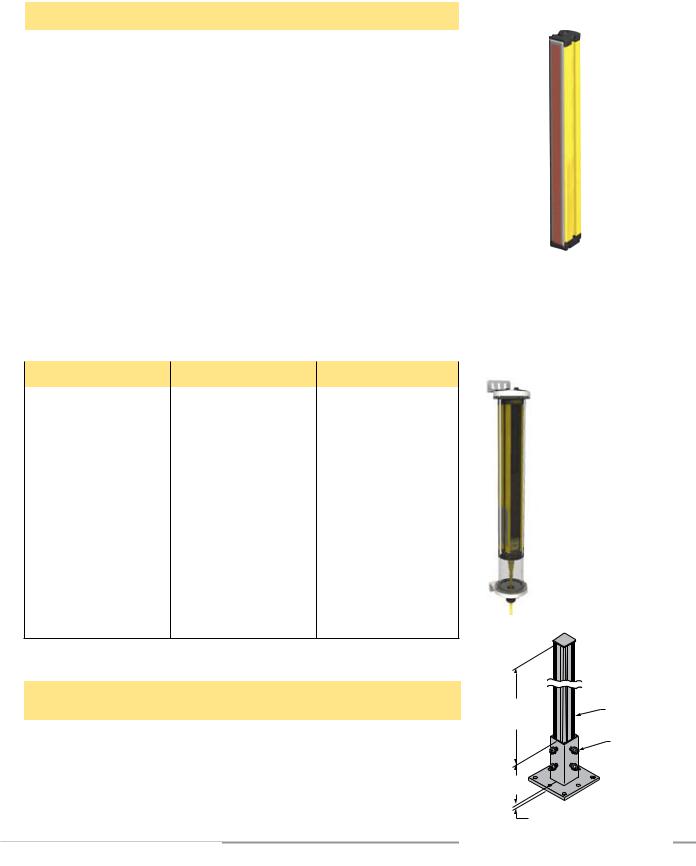
|
|
Overview |
|
|
|
|
EZ-SCREEN |
|
|
andSpecifications |
|
|
|||
|
|
|
|
||||
|
|
|
|
Instruction Manual |
|||
|
|
Components |
|
|
|||
|
|
|
|
|
|
|
|
|
|
Lens Shields |
|
|
|
|
|
|
|
NOTE: The total sensing range decreases by approximately 10% per shield. |
|
|
|||
|
|
Sensor Defined Area † |
Adhesive-Backed Model (1) |
Snap-On Model (2) |
|
||
|
|
150 mm |
EZS-150 |
EZSS-150 |
|
||
|
|
300 mm |
EZS-300 |
EZSS-300 |
|
||
|
|
450 mm |
EZS-450 |
EZSS-450 |
|
||
|
|
600 mm |
EZS-600 |
EZSS-600 |
|
||
|
|
750 mm |
EZS-750 |
EZSS-750 |
|
||
|
|
900 mm |
EZS-900 |
EZSS-900 |
|
||
|
|
1050 mm |
EZS-1050 |
EZSS-1050 |
|
||
|
|
|
|
|
|
||
|
|
1200 mm |
EZS-1200 |
EZSS-1200 |
|
||
|
|
1350 mm |
EZS-1350 |
EZSS-1350 |
|
||
|
|
1500 mm |
EZS-1500 |
EZSS-1500 |
|
||
|
|
1650 mm |
EZS-1650 |
EZSS-1650 |
|
||
|
|
|
|
|
|
||
|
|
1800 mm |
EZS-1800 |
EZSS-1800 |
Adhesive-backed model shown |
||
|
|
†Contact factory for lens shield availability for longer sensor lengths. |
|
||||
|
|
|
|
||||
(1)Polycarbonate shield guards against weld splatter and weld flash with an adhesive-backed neoprene gasket (see data sheet p/n 61960).
(2)Copolyester shield provides heavy-duty, impact-resistant protection from many types of cutting fluids (see data sheet p/n 127944).
Tubular Enclosures
EZA-MBK-2 adapter bracket is required for use with MSA Series stand, see page 14 and data sheet P/N 117107.
Enclosure Model † |
Enclosure Height |
For EZ-SCREEN Models |
EZA-TE-150 |
439 mm (17.3") |
SLS..-150 |
|
|
|
EZA-TE-300 |
541 mm (21.3") |
SLS..-300 |
EZA-TE-450 |
744 mm (29.3") |
SLS..-450 |
EZA-TE-600 |
846 mm (33.3") |
SLS..-600 |
EZA-TE-750 |
1024 mm (40.3") |
SLS..-750 |
|
|
|
EZA-TE-900 |
1151 mm (45.3") |
SLS..-900 |
|
|
|
EZA-TE-1050 |
1354 mm (53.3") |
SLS..-1050 |
|
|
|
EZA-TE-1200 |
1455 mm (57.3") |
SLS..-1200 |
|
|
|
EZA-TE-1350 |
1608 mm (63.3") |
SLS..-1350 |
|
|
|
EZA-TE-1500 |
1760 mm (69.3") |
SLS..-1500 |
|
|
|
EZA-TE-1650 |
1913 mm (75.3") |
SLS..-1650 |
|
|
|
EZA-TE-1800 |
2065 mm (81.3") |
SLS..-1800 |
†Contact factory for enclosure availability for longer sensor lengths.
MSA Series Stands (Base Included)*
Stand |
Pole |
Useable Stand |
Overall Stand Height |
|
Model |
Height |
Height |
||
|
||||
MSA-S24-1 |
610 mm (24") |
483 mm (19") |
616 mm (24.25") |
|
MSA-S42-1 |
1067 mm (42") |
940 mm (37") |
1073 mm (42.25") |
|
MSA-S66-1 |
1676 mm (66") |
1550 mm (61") |
1682 mm (66.25") |
|
MSA-S84-1 |
2134 mm (84") |
2007 mm (79") |
2140 mm (84.25") |
|
MSA-S105-1 |
2667 mm (105”) |
2667 mm (100”) |
2673 mm (105.25”) |
*Available without a base by adding the suffix “NB” to model number, e.g., MSA-S42-1NB.
12 P/N 11285233487 rev. F
Explosion-proof enclosures also available. Contact factory or visit www.bannerengineering.com for more information.
Useable |
Pole |
Stand |
40 mm |
Height |
(1.58") Square |
|
(4) M10 Bolt |
127 mm |
|
(5.0") |
|
|
Base Plate Thickness |
Banner Engineering Corp. • Minneapolis, U.S.A.
www.bannerengineering.com • Tel: 763.544.3164

EZ-SCREEN |
Overview |
Instruction Manual |
Components and Specifications |
|
MSM Series Corner Mirrors |
|
Rear-surface glass mirrors rated at 85% efficiency. The total sensing range decreases by |
M4 x 10 mm |
approximately 8% per mirror. See mirror data sheet P/N 43685 or the Banner Safety catalog |
Screw |
for further information. |
(8 supplied) |
 53.8 mm (2.12")
Y
L1
L2
50.8 mm (2.00")
72.9 mm (2.87")
Defined Area |
Mirror |
Reflective Area |
Mounting |
Height |
Length |
Model |
Y |
L1 |
L2 |
150 mm (5.9") |
MSM8A |
267 mm (10.5") |
323 mm (12.7") |
292 mm (11.5") |
|
|
|
|
|
300 mm (11.8") |
MSM12A |
356 mm (14") |
411 mm (16.2") |
381 mm (15") |
|
|
|
|
|
450 mm (17.7") |
MSM20A |
559 mm (22") |
615 mm (24.2") |
584 mm (23") |
|
|
|
|
|
600 mm (23.6") |
MSM24A |
660 mm (26") |
716 mm (28.2") |
686 mm (27") |
|
|
|
|
|
750 mm (29.5") |
MSM32A |
864 mm (34") |
919 mm (36.2") |
889 mm (35") |
|
|
|
|
|
900 mm (35.4") |
MSM36A |
965 mm (38") |
1021 mm (40.2") |
991 mm (39") |
|
|
|
|
|
1050 mm (41.3") |
MSM44A |
1168 mm (46") |
1224 mm (48.2") |
1194 mm (47") |
|
|
|
|
|
1200 mm (47.2") |
MSM48A |
1270 mm (50") |
1326 mm (52.2") |
1295 mm (51") |
|
|
|
|
|
|
|
SSM Series Corner Mirrors |
|
M6 x 19 mm |
|
• Rear-surface glass mirrors rated at 85% efficiency. The total sensing range decreases by |
|
(3.98") |
approximately 8% per mirror. See mirror data sheet P/N 61934 or the Banner Safety catalog |
||
(4 supplied) |
|||
screw |
101.2 mm |
|
for further information.
• Robust construction, two mounting brackets and hardware included.
M5 x 10 mm |
|
• EZA-MBK-2 adapter bracket is required for use with MSA Series stand, see page 14. |
||||
(4 supplied) |
|
|||||
screw |
|
|
|
|
|
|
L3 |
Y |
Defined Area |
Mirror |
Reflective Area |
Mounting |
Height |
|
||||||
|
Length |
Model* |
Y |
L1 |
L2 |
|
L1 |
|
|||||
|
|
|
|
|
|
|
|
|
150 mm (5.9") |
SSM-200 |
200 mm (7.9") |
278 mm (10.9") |
311 mm (12.2") |
|
|
300 mm (11.8") |
SSM-375 |
375 mm (14.8") |
486 mm (19.1") |
453 mm (17.8") |
L2 |
|
450 mm (17.7") |
SSM-550 |
550 mm (21.7") |
661 mm (26.0") |
628 mm (24.7") |
100 mm |
|
|||||
|
|
|
|
|
|
|
(3.94") |
|
600 mm (23.6") |
SSM-675 |
675 mm (26.6") |
786 mm (31.0") |
753 mm (29.6") |
115 mm |
|
|||||
(4.53") |
|
750 mm (29.5") |
SSM-825 |
825 mm (32.5") |
936 mm (36.9") |
903 mm (35.6") |
|
|
|||||
NOTE: Brackets may be inverted from the |
|
900 mm (35.4") |
SSM-975 |
975 mm (38.4") |
1086 mm (42.8") |
1053 mm (41.5") |
positions shown above, decreasing |
|
|||||
dimension L1 by 58 mm (2.3"). |
|
1050 mm (41.3") |
SSM-1100 |
1100 mm (43.3") |
1211 mm (47.7") |
1178 mm (46.4") |
|
|
|||||
|
|
1200 mm (47.2") |
SSM-1275 |
1275 mm (50.2") |
1386 mm (54.6") |
1353 mm (53.3") |
|
|
1350 mm (53.1") |
SSM-1400 |
1400 mm (55.1") |
1511 mm (59.5") |
1478 mm (58.2") |
|
|
1500 mm (59.0") |
SSM-1550 |
1550 mm (61.0") |
1661 mm (65.4") |
1628 mm (64.1") |
|
|
1650 mm (65.0") |
SSM-1750 |
1750 mm (68.9") |
1861 mm(73.3") |
1828 mm (72.0") |
|
|
1800 mm (70.9") |
SSM-1900 |
1900 mm (74.8") |
2011 mm (79.2") |
1978 mm (77.9") |
*Stainless steel reflective surface models also available by adding model number suffix “-S” (e.g., SSM-200-S); range reduction for these models is approximately 30% per mirror. See data sheet p/n 67200.
Banner Engineering Corp. • Minneapolis, U.S.A.
www.bannerengineering.com • Tel: 763.544.3164 |
P/N 133487 |
13 |
|

|
|
Overview |
|
EZ-SCREEN |
|
|
andSpecifications |
||
|
|
|||
|
|
Instruction Manual |
||
|
|
Components |
||
|
|
|
|
|
Accessory Mounting Brackets
See Section 2.5 for standard brackets. Contact factory for more information. Order one
EZA-MBK-.. bracket per sensor, two per pair.
Model |
Description |
|
|
|
|
EZA-MBK-2 |
Adapter bracket for mounting SSM series mirror to |
|
MSA series stands |
||
|
||
|
|
|
|
• Universal adapter bracket for mounting to |
|
EZA-MBK-20 |
engineered/slotted aluminum framing |
|
(e.g., 80/20™, Unistrut™). |
||
|
||
|
• Retrofit for Banner MS/US/MG. |
|
|
|
|
|
Mounting bracket system for “L” configuration of two |
|
EZA-MBK-21 |
cascaded light screens. Order one per side. See |
|
Figure 7-1, data sheet p/n 121007, or contact factory |
||
|
for more information. |
|
|
NOTE: Special end brackets included, but not shown. |
|
|
|
|
EZA-MBK-8 |
Retrofit for Sick FGS and Leuze L-bracket |
|
|
|
|
EZA-MBK-13 |
Retrofit for Sick C4000, |
|
AB SafeShield/GuardShield, |
||
|
Omron FS3N, STI MC42/47 |
|
|
|
|
EZA-MBK-14 |
Retrofit for STI MS4300 |
|
|
|
|
EZA-MBK-15 |
Retrofit for STI MS46/47, Keyence PJ-V, |
|
SUNX SF4-AH |
||
|
|
EZA-MBK-20 |
|
|
50.0 mm |
|
|
(1.97") |
|
|
44.4 mm |
|
|
(1.75") |
|
|
20 mm |
|
4.2 mm |
(0.79") |
|
C |
||
(0.17") |
L |
|
|
39.2 mm |
|
|
(1.54") |
|
58.2 mm |
40 mm |
|
(2.29") |
||
(1.57") |
||
|
EZA-MBK-18 |
Retrofit for Dolan-Jenner SS7 |
Banner Engineering Corp. • Minneapolis, U.S.A.
14 |
P/N 11285233487 rev. F |
|
www.bannerengineering.com • Tel: 763.544.3164 |
|
|
||
|
|
|
|

EZ-SCREEN
Instruction Manual
Alignment Aids
Components and SpecificationsOverview
|
Model |
Description |
|
|
|
|
|
|
LAT-1-SS |
Self-contained visible-beam laser tool for aligning any EZ-SCREEN |
|
|
14 mm and 30 mm emitter/receiver pair. Includes retroreflective target |
||
|
|
material and mounting clip. |
|
|
EZA-LAT-SS |
Replacement adaptor (clip) hardware for SLS.. models |
|
LAT-1 |
EZA-LAT-2 |
Clip-on retroreflective LAT target |
|
|
|
||
BRT-THG-2-100 |
2" retroreflective tape, 100' |
||
|
|||
|
BT-1 |
Beam Tracker |
EZ-LIGHT™ for EZ-SCREEN®
Provides clear, 360° indication of the EZ-SCREEN receiver’s output status. Use with a CSB splitter cable and optional DEE2R double-ended cables (see page 9). See data sheet 121901 for more information.
Models |
Construction |
Connector |
LED Function |
Inputs |
|
|
|
Nickel-plated brass housing, |
|
|
|
|
M18RGX8PQ8 |
thermoplastic dome, |
|
|
|
|
(See Note below*) |
M18x1 thread mount |
|
|
|
|
|
Fully encapsulated, IP67 |
|
|
|
|
|
|
|
|
|
|
|
Thermoplastic polyester |
|
|
|
|
T18RGX8PQ8 |
housing, thermoplastic dome, |
|
|
|
|
18 mm mount |
|
|
|
|
|
|
Fully encapsulated, IP67 |
|
|
|
|
|
|
|
|
|
|
|
Thermoplastic polyester |
|
Red/Green |
|
|
|
housing, thermoplastic dome, |
|
|
|
|
T30RGX8PQ8 |
|
indication follows |
|
|
|
30 mm mount |
|
|
||
|
|
Fully encapsulated, IP67 |
|
OSSD output of |
|
|
|
|
the EZ-SCREEN |
|
|
|
|
Polycarbonate housing, |
8-pin |
receiver |
|
|
|
ON Red: |
PNP |
||
|
K30LRGX8PQ8 |
30 mm thermoplastic dome, |
Euro-style |
||
|
22 mm mount |
integral QD |
Power ON |
(Sourcing) |
|
|
|
Fully encapsulated, IP67 |
|
Beam Blocked |
|
|
|
|
or Lockout |
|
|
|
|
|
|
|
|
|
|
Polycarbonate housing, |
|
ON Green: |
|
|
|
|
Power ON |
|
|
|
K50LRGX8PQ8 |
50 mm thermoplastic dome, |
|
Beam Clear |
|
|
30 mm mount |
|
|
|
|
|
|
Fully encapsulated, IP67 |
|
|
|
|
|
|
|
|
|
|
|
Polycarbonate housing, |
|
|
|
|
K80LRGX8PQ8 |
50 mm thermoplastic dome, |
|
|
|
|
flat or DIN mount |
|
|
|
|
|
|
Encapsulated electronics, IP67 |
|
|
|
|
|
|
|
|
|
*Available in a kit that includes one M18 EZ-LIGHT, one SMB18A mounting bracket, and hardware for mounting to the side channel of an EZ-SCREEN housing (kit model number EZA-M18RGX8PQ8).
Banner Engineering Corp. • Minneapolis, U.S.A.
www.bannerengineering.com • Tel: 763.544.3164 |
P/N 112852P/N133487rev. F |
15 |
|

ComponentsOverview andSpecifications
2.5 Replacement Parts
EZ-SCREEN
Instruction Manual
Description |
|
Model Number |
|
|
|
|
|
Panel-mount keyed reset switch |
|
MGA-KSO-1 |
|
|
|
|
|
Replacement key for switch MGA-KSO-1 |
|
MGA-K-1 |
|
Access cover with label – emitter |
|
EZA-ADE-1 |
|
Access cover with label – receiver |
|
EZA-ADR-1 |
|
|
|
|
|
Access cover with inverted label – emitter |
|
EZA-ADE-2 |
|
|
|
|
|
Access cover with inverted label – receiver |
|
EZA-ADR-2 |
|
Access cover security plate (includes 2 screws, wrench) |
EZA-TP-1 |
||
Wrench, security |
|
EZA-HK-1 |
|
|
|
|
|
14 mm test piece (for 14 mm resolution systems) |
|
STP-13 |
|
|
|
|
|
30 mm test piece (for 14 mm resolution systems with 2-beam Reduced |
STP-14 |
||
Resolution and for 30 mm resolution systems) |
|
||
|
|
||
60 mm test piece (for 30 mm resolution systems with 2-beam Reduced |
STP-15 |
||
Resolution) |
|
||
|
|
||
Terminator plug for cascaded receiver |
|
EZA-RTP-1 |
|
|
|
|
|
Dust cap for cascaded emitter |
|
p/n 64790 |
|
|
|
|
|
Standard bracket kit with hardware (includes 2 end |
Black |
EZA-MBK-11 |
|
brackets and hardware to mount to MSA Series |
|
|
|
Stainless Steel |
EZA-MBK-11N |
||
stands; see Figure 2-1) |
|||
|
|
|
|
Center bracket kit (includes 1 bracket and hardware to mount to MSA |
EZA-MBK-12 |
||
Series stands), and retrofit for SICK and Leuze Swivel (see Figure 2-1) |
|||
|
|||
SSM Mirror bracket kit (includes 2 replacement brackets for one mirror) |
SMA-MBK-1 |
||
|
|
|
|
2.6 Literature
The following documentation is supplied with each EZ-SCREEN receiver. Additional copies are available at no charge.
Description |
Part # |
|
|
EZ-SCREEN System Instruction Manual |
112852 |
|
|
Checkout Procedure Card (Daily) – Stand-Alone Systems |
113361 |
|
|
Checkout Procedure Card (Daily) – Cascaded Systems |
118173 |
|
|
Checkout Procedure Card (Semi-Annual) |
113362 |
|
|
Diagnostic Display Label |
114189 |
|
|
Banner Engineering Corp. • Minneapolis, U.S.A.
16 |
P/N 11285233487 rev. F |
|
www.bannerengineering.com • Tel: 763.544.3164 |
|
|
||
|
|
|
|

EZ-SCREEN |
|
|
|
|
|
|
Overview |
|
||
|
|
Components and |
|
|||||||
Instruction Manual |
|
|
|
|||||||
|
|
Specifications |
|
|||||||
|
2.7 Specifications |
|
|
|
|
|
|
|
|
|
|
2.7.1 General Specifications |
|
|
|
|
|
|
|
|
|
|
|
|
|
|
||||||
|
Short Circuit Protection |
All inputs and outputs are protected from short circuits to +24V dc or dc common. |
|
|||||||
|
Electrical Safety Class |
III |
|
|
|
|
|
|
|
|
|
(IEC 61140: 1997) |
|
|
|
|
|
|
|
||
|
|
|
|
|
|
|
|
|
|
|
|
Safety Rating |
Type 4 per IEC 61496-1, -2; Category 4 PL e, per EN ISO 13849-1; SIL 3 per IEC 61508; |
|
|||||||
|
|
SIL CL 3 per IEC 62061 |
|
|
|
|
|
|
|
|
|
Resolution† and |
14 mm models: 0.1 m to 6 m (4" to 20') |
|
|
|
|
|
|
|
|
|
Operating Range |
30 mm models: 0.1 m to 18 m (4" to 60') |
|
|
|
|
|
|
|
|
|
|
Range decreases with use of mirrors and/or lens shields: |
|
|
|
|
||||
|
|
Lens shields – approximately 10% less range per shield. |
|
|||||||
|
|
Glass-surface mirrors – approximately 8% less range per mirror. |
|
|||||||
|
†Not including blanking |
See the specific mirror data sheet or the Banner Safety Catalog for further information. |
|
|||||||
|
|
|
|
|
|
|
|
|||
|
Effective Aperture Angle |
Meets Type 4 requirements per IEC 61496-2, Section 5.2.9 |
|
|
|
|
||||
|
(EAA) |
± 2.5° @ 3 m |
|
|
|
|
|
|
|
|
|
Enclosure |
Size: See Figure 2-2 |
|
|
|
|
|
|
|
|
|
|
Materials: Extruded aluminum housing with yellow polyester powder finish standard (optional black or |
|
|||||||
|
|
white or nickel-plated silver finish) and well-sealed, rugged die-cast zinc end caps, acrylic |
|
|||||||
|
|
lens cover, copolyester access cover. End caps on silver models are also nickel-plated. |
|
|||||||
|
|
ESD-safe models have static-dissipative acrylic lens cover. |
|
|||||||
|
|
Rating: IEC IP65 |
|
|
|
|
|
|
|
|
|
Operating Conditions |
Temperature: 0° to +55° C (+32° to 131°F) |
|
|
|
|
|
|
|
|
|
|
Max. Relative Humidity: 95% maximum relative humidity (non-condensing) |
|
|||||||
|
Shock and Vibration |
EZ-SCREEN components have passed vibration and shock tests according to IEC 61496-1. This |
|
|||||||
|
|
includes vibration (10 cycles) of 10-55 Hz at 0.35 mm (0.014") single amplitude (0.70 mm peak-to- |
|
|||||||
|
|
peak) and shock of 10 g for 16 milliseconds (6,000 cycles). |
|
|
|
|
||||
|
Mounting Hardware |
Emitter and receiver each are supplied with a pair of swivel end-mounting brackets. Models longer |
|
|||||||
|
|
than 900 mm also include a swivel center-mount bracket. Mounting brackets are 8-gauge cold-rolled |
|
|||||||
|
|
steel, black zinc finish. |
|
|
|
|
|
|
|
|
|
Cables and Connections |
See Section 2.3 for recommended QD cables. If other cables are used with the EZ-SCREEN, the user |
|
|||||||
|
|
must verify suitability of these cables for each application. |
|
|
|
|
||||
|
Certifications |
IEC 61496-1, -2: Type 4 |
|
|
|
NIPF(7) |
|
|||
|
|
C |
|
US |
|
|||||
|
|
EN ISO 13849-1: Cat 4 PL e |
R |
UL1998, UL61496 |
|
|||||
|
|
|
|
|
|
|
|
|
|
|
|
|
|
|
|
|
|
|
|
|
|
|
|
|
|
|
|
|
|
|
|
|
Banner Engineering Corp. • Minneapolis, U.S.A.
www.bannerengineering.com • Tel: 763.544.3164 |
P/N 112852P/N133487rev. F |
17 |
|

ComponentsOverview andSpecifications
EZ-SCREEN
Instruction Manual
2.7.2 Emitter Specifications
Supply Voltage at the Device |
24V dc ±15% (use a SELV-rated supply according to EN IEC60950) |
|
(The external voltage supply must be capable of buffering brief mains interruptions of 20 ms, as |
|
specified in IEC/EN 60204-1.) |
Residual Ripple |
± 10% maximum |
Supply Current |
100 mA max. |
Remote Test Input |
Test mode is activated either by applying a low signal (less than 3V dc) to emitter TEST #1 terminal for a |
(Optional – available only on |
minimum of 50 milliseconds, or by opening a switch connected between |
model SLSE..-..Q5 emitters) |
TEST #1 and TEST #2 for a minimum of 50 milliseconds. Beam scanning stops to simulate a blocked |
|
condition. A high signal at TEST #1 deactivates Test Mode. (See Section 3.5.6 for more information.) |
|
High Signal: 10 to 30V dc |
|
Low Signal: 0 to 3V dc |
|
Input Current: 35 mA inrush, 10 mA max. |
Controls and Adjustments |
Scan Code Selection: 2-position switch (code 1 or 2). Factory default position is code 1. |
Status Indicators |
One bi-color (Red/Green) Status indicator – indicates operating mode, lockout or power OFF |
|
condition |
|
7-Segment Diagnostic indicator (1 digit) – indicates proper operation, scan code, or error code |
|
See Figure 1-4 for indicator locations and Section 4.4 for indicator conditions. |
Wavelength of Emitter Elements |
Infrared LEDs, 950 nm at peak emission (14 mm) 850 nm at peak emission (30 mm) |
2.7.3 Receiver Specifications
|
Supply Voltage at the Device |
24V dc ±15% (use a SELV-rated supply according to EN IEC60950) |
|
|
|
|
|
||||||
|
|
(The external voltage supply must be capable of buffering brief mains interruptions of 20 ms, as |
|
|
|||||||||
|
|
specified in IEC/EN 60204-1.) |
|
|
|
|
|
|
|
||||
|
Residual Ripple |
± 10% maximum |
|
|
|
|
|
|
|
|
|
||
|
Supply Current (no load) |
275 mA max., exclusive of OSSD1 and OSSD2 loads (up to an additional 0.5A each) |
|
|
|||||||||
|
Response Time |
Dependent on number of sensing beams (see Section 2.1 for models and number of beams): |
|
|
|||||||||
|
|
|
|
10 beams – 9 ms |
60 beams – 19 ms |
110 beams – 30 ms |
160 beams – 40 ms |
|
|
||||
|
|
|
|
20 beams – 11 ms |
70 beams – 21 ms |
120 beams – 32 ms |
180 beams – 43 ms |
|
|
||||
|
|
|
|
30 beams – 13 ms |
80 beams – 23 ms |
130 beams – 34 ms |
200 beams – 48 ms |
|
|
||||
|
|
|
|
40 beams – 15 ms |
90 beams – 25 ms |
140 beams – 36 ms |
220 beams – 52 ms |
|
|
||||
|
|
|
|
50 beams – 17 ms |
100 beams – 27 ms |
150 beams – 38 ms |
240 beams – 56 ms |
|
|
||||
|
|
|
|
|
|
|
|
|
|
|
|
||
|
|
|
For cascaded systems, also see Section 7.4. |
|
|
|
|
|
|
|
|||
|
CSSI Response Time |
Response time for a cascade receiver due to opening contacts at the cascade interface (CSSI): 40 ms |
|
|
|||||||||
|
(SLSC.. cascade models only) |
max (contacts must open for 60 ms minimum). See Section 7.5. |
|
|
|
|
|
||||||
|
Recovery Time — Blocked to Clear |
|
|
|
|
|
|
|
|
|
|
|
|
|
|
|
|
|
Beam 1 (Sync Beam) |
All Other Beams |
|
|
|
||||
|
(OSSDs turn ON; varies with total |
|
|
|
|
|
|
|
|||||
|
|
|
14 mm Models |
|
109 ms to 800 ms |
33 ms to 220 ms |
|
|
|
||||
|
number of sensing beams and |
|
|
|
|
|
|
||||||
|
whether Sync beam is blocked) |
|
|
30 mm Models |
|
81 ms to 495 ms |
|
|
25 ms to 152 ms |
|
|
|
|
|
|
|
|
|
|
|
|
|
|
|
|
|
|
|
EDM Input |
+24V dc signals from external device contacts can be monitored (one-channel, two-channel or no |
|
|
|||||||||
|
|
monitoring) via EDM1 and EDM2 terminals in the receiver (see Section 3.5.3). |
|
|
|
|
|||||||
|
|
High Signal: 10 to 30V dc at 30 mA typical |
|
|
|
|
|
|
|
||||
|
|
Low Signal: 0 to 3V dc |
|
|
|
|
|
|
|
|
|
||
|
|
Dropout Time: 200 ms max. |
|
|
|
|
|
|
|
||||
|
Reset Input |
The Reset input must be high for 1/4 to 2 seconds and then low to reset the receiver. |
|
|
|||||||||
|
|
High Signal: 10 to 30V dc at 30 mA typical |
|
|
|
|
|
|
|
||||
|
|
Low Signal: 0 to 3V dc |
|
|
|
|
|
|
|
|
|
||
|
|
Closed Switch Time: 1/4 to 2 seconds |
|
|
|
|
|
|
|
||||
|
|
|
|
|
|
|
|
|
|
|
|
|
|
|
|
|
|
|
|
|
|
Banner Engineering Corp. • Minneapolis, U.S.A. |
|
|
|||
18 |
P/N 11285233487 rev. F |
|
|
|
|
|
|
www.bannerengineering.com • Tel: 763.544.3164 |
|
|
|||
|
|
|
|
|
|
|
|
|
|
|
|
||
|
|
|
|
|
|
|
|
|
|
|
|
||
|
|
|
|
|
|
|
|
|
|
|
|
|
|
EZ-SCREEN
Instruction Manual
2.7.3 Receiver Specifications, continued
Components and SpecificationsOverview
Output Signal Switching Devices |
Two redundant solid-state 24V dc, 0.5 A max. sourcing OSSD (Output Signal Switching Device) safety |
(OSSDs) |
outputs. (Use optional interface modules for ac or larger dc loads.) |
|
Capable of the Banner “Safety Handshake” (see Section 1.1). |
|
ON-State voltage: ≥ Vin-1.5V dc |
|
OFF-State voltage: 1.2V dc max. (0-1.2V dc) |
|
Max. load capacitance: 1.0 µF |
|
Max. load inductance: 10 H |
|
Leakage Current: 0.50 mA maximum |
|
Cable Resistance: 10 Ω maximum |
|
OSSD test pulse width: 100 to 300 microseconds |
|
OSSD test pulse period: 10 ms to 27 ms (varies with number of beams) |
|
Switching Current: 0-0.5 A |
Auxiliary (Aux.) Output Switching |
Current-sourcing (PNP) solid-state output, 24V dc at 75mA max (see Section 3.5.5). |
Capacity |
|
|
|
Controls and Adjustments |
Scan Code selection: 2-position switch (code 1 or 2). Factory default position is code 1. |
|
Trip/Latch Output selection: Redundant switches. Factory default position is T (trip). |
|
EDM/MPCE monitor selection: 2-position switch selects between 1- or 2-channel monitoring. Factory |
|
default position is 2. |
|
Reduced Resolution: Redundant switches. Factory default position is OFF. |
|
|
Ambient Light Immunity |
> 10,000 lux at 5° angle of incidence |
|
|
Strobe Light Immunity |
Totally immune to one Federal Signal Corp. “Fireball” model FB2PST strobe |
|
|
Status Indicators |
Yellow Reset indicator – indicates whether system is ready for operation or requires a reset |
|
Bi-color (Red/Green) Status indicator – indicates general system and output status |
|
Bi-color (Red/Green) Zone Status indicators – indicate condition (clear or blocked beam) of a |
|
defined group of beams |
|
7-Segment Diagnostic indicator (3 digits) – indicates proper operation, scan code, or error code, |
|
total number of blocked beams |
|
See Figure 1-4 for indicator locations and Section 4.4 for indicator conditions. |
End Cap Brackets
(model EZA-MBK-11*)
4 x R 19.4 mm (0.76") 

4 x 45
50 mm (1.96")
2 x 5 mm (0.20")
2 x 15 mm (0.59")
20 mm (0.79")
4 x 5.8 mm (0.23") wide slots
Ø 21.5 mm (0.85")
Ø 33 mm (1.30")
38.2 mm (1.50")
2 x 7 mm (0.28")
2 x R 5 mm (0.20")
63.2 mm
4.2 mm (2.49") (0.17")
25 mm (0.98")
*Dimensions are identical for stainless steel model EZA-MBK-11N stainless steel brackets for ESD model emitters and receivers.
Center Bracket
(model EZA-MBK-12**)
Ø 60 mm 
20 mm |
20 mm |
(0.79") |
(0.79") |
**Supplied with emitters
and receivers over 1050 mm.
|
|
|
|
20 mm |
|
|
|
|
(0.79") |
|
55 mm |
|
|
|
|
(2.17") |
|
|
|
|
|
50 mm |
|
17.5 mm |
|
|
|
(0.69") |
|
|
|
(1.97") |
|
|
|
|
|
|
|
55.6 mm |
4.2 mm |
|
|
|
(2.19") |
|
|
|
|
(0.17") |
|
|
|
|
|
|
|
|
|
9.5 mm |
|
10 mm |
|
|
|
(0.39") |
|
||
(0.37") |
|
Ø 8.3 mm |
||
|
|
|||
|
|
|
|
(0.33") |
36 mm |
|
|
|
|
(1.42") |
|
|
|
|
|
|
|
|
Ø 7 mm |
|
|
|
|
(0.28") |
|
15 mm |
|
20.0 mm |
|
|
(0.59") |
|
(0.79") |
|
Figure 2-1. Included mounting bracket dimensions (for emitter or receiver)
Banner Engineering Corp. • Minneapolis, U.S.A.
www.bannerengineering.com • Tel: 763.544.3164 |
P/N 112852P/N133487rev. F |
19 |
|

ComponentsOverview andSpecifications
EZ-SCREEN
Instruction Manual
|
|
|
|
|
|
|
|
|
|
|
36.0 mm |
|
|
|
|
|
|
|
|
||||
45.2 mm |
12 mm* |
|
|
|
|
|
|
|
|
(1.42") |
|
(1.78") |
|
|
|
|
|
|
|
|
|
||
(0.47") |
|
|
|
|
|
|
|
|
|
|
|
|
|
|
|
|
|
|
|
|
|
|
|
|
|
|
|
|
|
|
|
|
|
|
|
|
|
|
|
|
|
|
|
|
|
|
|
|
|
|
|
|
|
|
|
|
|
|
|
Y |
|
L1 |
L2 |
|
|
56.0 mm |
|
(2.20") |
|
4.2 mm |
|
(0.17") |
|
*For SLS..-150 models, this distance is 52 mm (2")
See page 19 for detailed bracket dimensions.
L3
65 mm |
R13 mm (0.5") |
(2.6") |
minimum bend |
Emitter / Receiver |
Housing Length |
Distance Between Bracket Holes |
Defined Area† |
||
Model |
L1 |
L2 |
L3 |
Y |
|
SLS..-150 |
262 mm (10.3") |
295 mm (11.6") |
237 mm (9.3") |
150 mm (5.9") |
|
SLS..-300 |
372 mm (14.6") |
405 mm (16.0") |
347 mm (13.7") |
300 mm (11.8") |
|
SLS..-450 |
522 mm (20.6") |
555 mm (21.9") |
497 mm (19.6") |
450 mm (17.7") |
|
SLS..-600 |
671 mm (26.4") |
704 mm (27.7") |
646 mm (25.4") |
600 mm (23.6") |
|
SLS..-750 |
821 mm (32.3") |
854 mm (33.6") |
796 mm (31.3") |
750 mm (29.5") |
|
SLS..-900 |
971 mm (38.2") |
1004 mm (39.5") |
946 mm (37.2") |
900 mm (35.4") |
|
SLS..-1050 |
1120 mm (44.1") |
1153 mm (45.4") |
1095 mm (43.1") |
1050 mm (41.3") |
|
SLS..-1200 |
1270 mm (50.0") |
1303 mm (51.3") |
1245 mm (49.0") |
1200 mm (47.2") |
|
SLS..-1350 |
1420 mm (55.9") |
1453 mm (57.2") |
1395 mm (54.9") |
1350 mm (53.1") |
|
SLS..-1500 |
1569 mm (61.8") |
1602 mm (63.1") |
1544 mm (60.8") |
1500 mm (59.1") |
|
SLS..-1650 |
1719 mm (67.7") |
1752 mm (69.0") |
1694 mm (66.7") |
1650 mm (65.0") |
|
SLS..-1800 |
1869 mm (73.6") |
1902 mm (74.9") |
1844 mm (72.6") |
1800 mm (70.9") |
|
SLS..-1950 |
2018 mm (79.4") |
2051 mm (80.8") |
1993 mm (78.5") |
1950 mm (76.8") |
|
SLS..-2100 |
2168 mm (85.4") |
2201 mm (86.7") |
2143 mm (84.4") |
2100 mm (82.7") |
|
SLS..-2250 |
2318 mm (91.3") |
2351 mm (92.6") |
2293 mm (90.3") |
2250 mm (88.6") |
|
SLS..-2400 |
2468 mm (97.2") |
2501 mm (98.5") |
2443 mm (96.2") |
2400 mm (94.5") |
|
|
|
|
|
|
|
†Nominal measurement |
|
|
|
|
|
|
Figure 2-2. Emitter and receiver mounting dimensions and location of defined area |
|
|
|
|
|
|
|
|
|
Banner Engineering Corp. • Minneapolis, U.S.A. |
20 |
P/N 11285233487 rev. F |
|
www.bannerengineering.com • Tel: 763.544.3164 |
|
|
||
|
|||
|
|
|
|

EZ-SCREEN
Instruction Manual
Installation and OverviewAlignment
3. Installation and Alignment
Before installing the EZ-SCREEN System, read Section 1.2 and Section 3 of this manual in their entirety. The System’s ability to perform its safety guarding function depends upon the appropriateness of the application and upon its proper mechanical and electrical installation and interfacing to the guarded machine. If all mounting, installation, interfacing, and checkout procedures are not followed properly, the System cannot provide the protection for which it was designed.
Installation must be performed by a Qualified Person, as defined in Section 4.1. See Warning below.
WARNING . . . Read this Section Carefully Before Installing the System
The user is responsible for satisfying all local, state, and national codes and regulations relating to the installation and use of this control system in any particular application. Take extreme care to meet all legal requirements and follow all technical installation and maintenance instructions contained in this manual.
The user has the sole responsibility to ensure that the EZ-SCREEN System is installed and interfaced to the guarded machine by Qualified Persons in accordance with this manual and with applicable safety regulations.
Read Section 1.2 and all of Section 3 of this manual carefully before installing the system. Failure to follow these instructions could result in serious bodily injury or death.
3.1 Mechanical Installation Considerations
The two factors that influence the layout of the EZ-SCREEN’s mechanical installation the most are separation distance and hard guarding. Other considerations include emitter and receiver orientation, adjacent reflective surfaces, use of corner mirrors, and installation of multiple EZ-SCREEN emitter/receiver pairs.
WARNING . . . Position Components Carefully
The emitter and receiver must be positioned such that the hazard can not be accessed by reaching over, under, around or through the sensing field. Additional guarding may be required; see Separation Distance, Section 3.1.1, and Pass-Through Hazards, Section 3.1.2, and Supplemental Safeguarding, Section 3.1.4.
3.1.1 Separation Distance (Safety Distance)
Minimum Separation Distance (Ds) is the minimum distance required between the defined area and the closest reachable hazard point. Separation distance is calculated so that when an object or a person is detected (by blocking a sensing beam), the EZ-SCREEN will send a stop signal to the machine, causing it to stop by the time the person can reach any machine hazard point.
Calculation of separation distance takes into account several factors, including a calculated human speed, the total system stopping time (which itself has several components), and the depth penetration factor. After the separation distance (Ds) is determined, record the calculated distance on the Daily Checkout Card.
 WARNING . . . Proper Separation Distance
Banner EZ-SCREEN emitters and receivers must be mounted at a distance from the nearest hazard such that an individual cannot
reach the hazard before cessation of hazardous motion or situation.
Failure to establish and maintain the minimum separation distance could result in serious bodily injury or death.
Hard Guarding
Hard
Guarding
Robot
Turntable
Ds |
|
EZ-SCREEN |
|
EZ-SCREEN |
Nearest Hazard Point |
Reset Switch |
|
Figure 3-1. Separation distance and hard guarding
Banner Engineering Corp. • Minneapolis, U.S.A.
www.bannerengineering.com • Tel: 763.544.3164 |
P/N 133487 |
21 |
|
 Loading...