


|
MINI-BEAM® Universal Voltage Series |
Installation |
|
|
Guide |
|
Photoelectric sensors with electromechanical relay output |
|
|
|
|
Additional information on this product is immediately available online at www.bannerengineering.com/69944
View or download additional information, including excess gain curves, beam patterns and accessories.
For further assistance, contact a Banner Engineering Applications Engineer at (763) 544-3164 or (888) 373-6767.
|
|
Sensing Mode |
Range |
LED |
Model* |
|
|
Opposed Emitter |
3 m (10') |
|
SMU31E |
|
|
|
|
|
|
|
|
Opposed Receiver |
|
Infrared |
SMU31R |
|
|
|
|
|
|
|
|
Opposed Emitter - Long Range |
|
880 nm |
SMU31EL |
|
|
|
|
||
|
|
|
30 m (100') |
|
|
|
|
Opposed Receiver - Long Range |
|
|
SMU31RL |
|
|
Non-Polarized Retroreflective |
5 m (15') |
Visible Red |
SMU315LV |
|
|
|
|
|
|
|
P |
Polarized Retroreflective |
10 mm to 3 m |
650 nm |
SMU315LP |
|
|
||||
|
(0.4" to 10') |
|
|||
|
Emitters |
Diffuse |
380 mm (15") |
Infrared |
SMU315D |
|
|
|
|
||
|
|
Divergent Diffuse |
130 mm (5") |
880 nm |
SMU315W |
|
|
|
|||
bn |
+ |
|
16 mm (0.65") |
|
|
|
|
|
SMU315CV |
||
bu |
24-240V ac/dc |
|
1.3 mm (0.05") † |
Visible Red |
|
- |
Convergent |
|
|||
|
|
||||
|
43 mm (1.7") |
650 nm |
SMU315CV2 |
||
|
|
|
|
||
|
|
|
3 mm (0.07") † |
|
|
|
|
|
|
|
|
All Models Except Emitters |
|
Range varies |
Infrared |
SMU315F |
|
|
880 nm |
||||
Glass Fiber Optic |
|
||||
|
|
|
|
||
bn |
|
depending on |
|
|
|
|
|
sensing mode |
Visible Red |
SMU315FV |
|
bu |
24-240V ac/dc |
|
and fiber |
|
|
|
650 nm |
|
|||
|
|
Plastic Fiber Optic |
optics used |
SMU315FP |
|
wh |
|
|
|||
NC |
|
|
|||
|
|
|
|
||
|
|
|
|
|
|
ye |
C |
* Standard 2 m (6.5') cable models are listed. For 9 m (30') cable, add suffix “W/30” to the model number |
bk |
NO |
(e.g., SMU31E W/30). |
|
|
† Spot size (diameter of sensing beam) at focus.
NOTES:
•Output Type for all models (except emitters) is SPDT Electromechanical Relay.
•Install transient suppressor (MOV) across contacts switching inductive loads.
•Connection of dc power is without regard to polarity.
•Maximum switching current is 3 amps (see specifications).
See Safety Use Warning on Back Page
Dimensions
|
|
Models |
with suffix |
E, EL, R, RL, LV, LP, D, CV, and CV2 |
|||
30.7 mm (1.21") |
|
||
|
|
3.2 mm (0.13") |
12.2 mm (0.48") |
|
|
|
ø 3 mm (ø0.11") |
|
|
|
|
|
|
|
Clearance (2) |
24.1 mm (0.95")
2 m (6.5') Cable |
|
|
Mounting Peg |
|
19.1 mm |
|
||
|
||
ø 6.3 mm x 2.5 mm |
|
(0.75") |
(ø 0.25" x 0.10") |
|
|
81.0 mm (3.19")
M18 x 1 x 15 mm Thread (Mounting Nut Supplied)
27.4 mm (1.08")
Model SMU315W |
Model SMU315FP |
Models with suffix F and FV |
||
|
|
Fiber Optic Fitting |
|
|
|
Bezel |
|
|
|
|
18.0 mm |
|
|
|
|
(0.71") |
|
|
|
|
|
16.2 mm (0.64") |
|
|
|
|
|
Fiber Optic |
|
|
|
|
Fitting |
|
66.8 mm |
13.2 mm (0.52") |
69.8 mm |
85.3 mm |
|
(2.63") |
(3.36") |
|||
|
(2.75") |
|||
|
|
31.2 mm |
||
|
|
|
||
|
|
|
(1.23") |
|
Printed in USA |
10/03 |
P/N 69944 |
|
|
MINI-BEAM® Universal Voltage Sensors |
|
Installation |
|
|
|
|
|
Guide |
|
|
|
|
|
|
|
|
|
|
|
|
Installation and Alignment |
|
|
|
|
|
|
|
|
|
||
MINI-BEAM sensors perform most reliably if they are properly aligned and securely mounted. For maximum mechanical stability, final-mount MINI-BEAM sensors through 18 mm diameter holes by their threaded barrel (where available), or use a mounting bracket. A complete selection of mounting brackets is available. Visit www.bannerengineering.com/69944, or contact the factory for information on mounting options.
Begin with line-of-sight positioning of the MINI-BEAM sensor to its emitter (opposed-mode sensing) or to its target (all other sensing modes). When using a retroreflective sensor, the target is the retroreflector (“retro target”). For diffuse or convergent sensing modes, the target is the object to be detected.
Apply power to the sensor (and to the emitter, if using the opposed mode). Advance the 15-turn Gain control to maximum (clockwise end of rotation), using a small flat-blade screwdriver. The Gain control is clutched at both ends to avoid damage, and will “free-wheel” when either endpoint is reached. See MINI-BEAM Sensor rear view illustration on page 2.
If the MINI-BEAM sensor is receiving its light signal, the red LED alignment indicator will be ON and flashing at a rate proportional to the signal strength (faster = more signal). Move the sensor (or move the retro target, if applicable) up-down-right-left (including angular rotation) to find the center of the movement zone within which the LED indicator remains ON. Reducing the Gain setting will reduce the size of the movement zone, and enable more precise alignment.
Repeat the alignment motions after each Gain reduction. When optimum alignment is acheived, mount sensor(s) (and the retro target, if applicable) solidly in that position. Increase the Gain to maximum.
Test the sensor by placing the object to be detected in the sensing position, then removing it. The Alignment Indicator LED should come ON when the sensing beam is established (Light condition), and go OFF when the beam is broken (Dark condition).
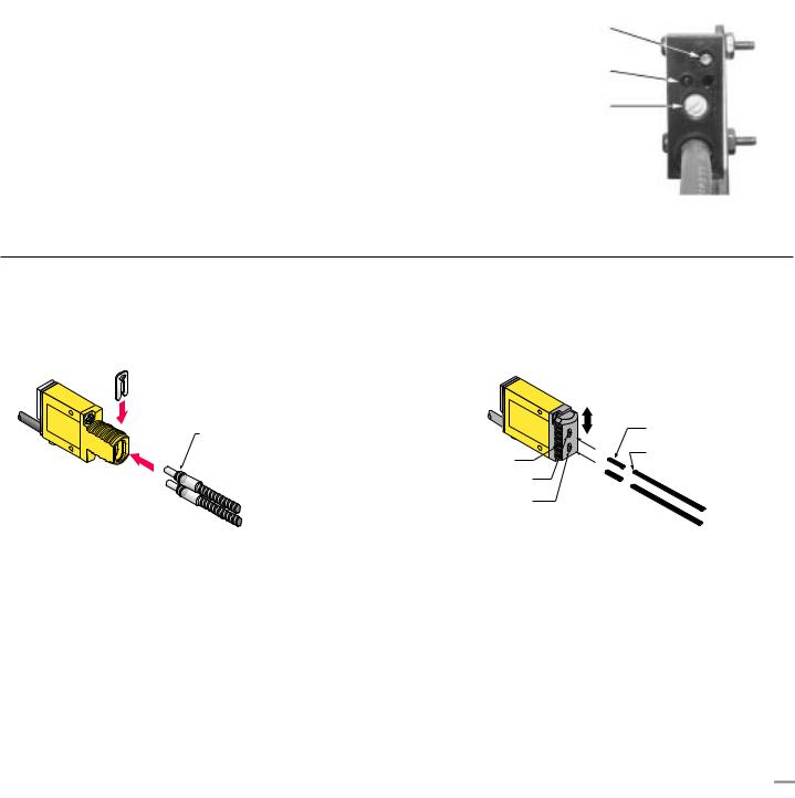
Sensor Rear View
(shown with gasketed acrylic cover removed)
Gain (Sensitivity) Adjustment Screw
Alignment Indicator Device (AID)*
Light/Dark Operate Selection Switch
Clockwise: Light Operate (outputs conduct when sensing light is received).
Counterclockwise: Dark Operate (outputs conduct when sensing light is not received).
*U.S. Patent no. 4356393
Fiber Installation
Glass Fiber Installation
1)Install the O-ring (supplied with the fiber) on each fiber end, as shown in the drawing.
2)While pressing the fiber ends firmly into the ports on the front of the sensor, slide the U-shaped retaining clip (supplied with the sensor) into the slot in the sensor’s barrel, until it snaps into place.
Retaining Clip
O-ring
Plastic Fiber Installation
1)With supplied fiber cutter, make a clean cut at control ends of fibers.
2)Unlock the fiber gripper as shown below. Apply appropriate fiber adaptors prior to fiber insertion, if needed.
3)Gently insert the prepared fiber ends into the ports, as far as they will go.
4)Slide the fiber gripper back to lock, as shown below.
Gripper |
|
|
Unlock |
Adaptors for |
|
Lock |
||
0.25and 0.5-mm fibers |
||
Sensor face |
Trimmed fiber |
|
control ends |
||
|
||
Plastic fiber |
|
|
receiver port |
|
|
Plastic fiber |
|
|
emitter port |
|
Banner Engineering Corp. • Minneapolis, MN U.S.A.
2 |
P/N 69944 |
www.bannerengineering.com • Tel: 763.544.3164 |
|
 Loading...