


L-GAGE® LT3 Long-Range Time-of-Flight Laser Sensor
Self-contained laser distance sensor, two discrete outputs
Features
•Extremely long range: 5 m with white targets, or 3 m with gray targets for diffuse mode sensors, up to 50 m for retroreflective models
•Two discrete (switched) outputs in each sensor, with independent window limits†
•Discrete outputs can be used for precision background suppression
•Output select wire is used to choose either NPN or PNP outputs (see hookups)
•Fast, easy-to-use integrated push-button TEACH-mode programming; no potentiometer adjustments
•Remote TEACH function for security and convenience
•Output response is programmable for three speeds
•High-grade retroreflective target included with each retroreflective-mode sensor
•Choose 2 m or 9 m unterminated cable, or 8-pin Euro-style swivel QD connector
•Rugged construction withstands demanding sensing environments; rated IEC IP67, NEMA 6
! WARNING . . .
Not To Be Used for Personnel Protection
Never use these products as sensing devices for personnel protection. Doing so could lead to serious injury or death.
These sensors do NOT include the self-checking redundant circuitry necessary to allow their use in personnel safety applications. A sensor failure
or malfunction can cause either an energized or de-energized sensor output condition. Consult your current Banner Safety Products catalog for safety products which meet OSHA, ANSI and IEC standards for personnel protection.
Models
Models |
Sensing |
Laser |
Sensing |
Cable* |
Supply |
Discrete |
|
Mode |
Class |
Distance |
Voltage |
Output |
|||
|
|
||||||
LT3BD |
|
|
|
2 m (6.5') |
|
|
|
|
|
0.3 to 5 m |
8-wire |
|
|
||
|
Diffuse |
Class 2 |
|
|
|||
LT3BDQ |
(11.8" to 16.4') |
8-pin |
|
NPN or |
|||
|
|
|
Euro-style QD |
12 to |
|||
|
|
|
|
PNP |
|||
|
|
|
|
2 m (6.5') |
24V dc |
||
LT3BDLV |
|
|
|
Selectable |
|||
Retro- |
|
0.5 to 50 m** |
8-wire |
|
|||
|
Class 1 |
|
|
||||
|
|
|
|
||||
LT3BDLVQ |
reflective |
(20" to 164') |
8-pin |
|
|
||
|
|
|
|||||
|
|
|
Euro-style QD |
|
|
||
|
|
|
|
|
|
||
|
|
|
|
|
|
|
*9 m cables are available by adding suffix “W/30” to the model number of any cabled sensor (e.g., LT3BD W/30). A model with a QD connector requires a mating cable; see page 11.
**Retroreflective range specified using included model BRT-TVHG-8X10P high-grade target.
!sensor contains no userserviceable components.
Do not attempt to repair.CAUTION . . . This
Incorrect component values may produce hazardous laser radiation levels.
†NOTE: See Banner website for information on analog/discrete models at: bannerengineering.com
Printed in USA |
02/05 |
P/N 68503 rev. C |
L-GAGE® LT3 Long-Range Time-of-Flight Sensor – Two Discrete Outputs
Theory of Operation
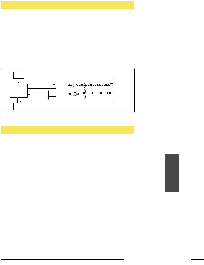
A short electrical pulse drives a semiconductor laser diode to emit a pulse of light. The emitted light is collimated through a lens, which produces a very narrow laser beam. The laser beam bounces off the target, scattering some of its light through the sensor’s receiving lens to a photodiode, which creates an electrical pulse. The time interval between the two electrical pulses (transmitting and receiving the beam) is used to calculate the distance to the target, using the speed of light as a constant.
Multiple pulses are evaluated by the sensor’s microprocessor, which calculates the appropriate position value. The discrete (switched) output energizes whenever the target is located between the user-programmed discrete window limits. Window limits for both discrete outputs may be the same, or they may be programmed independently.
User |
|
|
|
|
Interface |
|
|
|
|
|
|
Laser |
Lenses |
Target |
|
Emitter |
Emitter |
|
|
|
E |
|
|
|
|
Circuitry |
|
|
|
|
|
|
|
|
Microprocessor |
Analog |
|
|
|
Time-of-Flight |
R |
|
|
|
Signal |
|
|
||
Engine |
|
|
|
|
Processing |
Receiver |
|
|
|
|
|
|
||
|
|
|
|
|
|
|
Element |
|
|
Output |
|
|
|
|
Circuitry |
|
|
|
|
Figure 1. Theory of operation
Programming
Response Speed
Prior to setting window limits, use the sensor’s Speed push button to toggle between the three response speed settings. The selected speed will be indicated by one of the three Response Speed indicator LEDs (see Figure 2). See Specifications for further information.
Sensor Setup
Allow 30 minutes after power-up to allow the sensor’s internal temperature to stabilize, before operating or attempting to program the sensor. If the sensor will be used in applications where the temperature is several degrees higher or lower than ambient, allow the sensor to stabilize in that condition before programming the window limits. (Range will decrease as the sensor warms up.)
The laser enable feature allows the sensor to be continually powered, and enabled only when being used. This eliminates the need for the extended warm-up period between uses.
The sensor’s red Signal LED indicates the condition of the received signal from the object being measured. When programming window limits, this LED must be ON solid (not flashing) for the sensor to accept the setting. On diffuse-mode models, to ensure that the received signal will not be marginal during operation, move the target object 300 mm beyond the furthest desired set point during setup, and verify that the signal LED is still ON solid.
Window Limits
Window limits may be taught to the sensor in several ways. The following methods
(beginning on page 4) describe the programming procedures using the push buttons on the top of the sensor or via remote programming (remote TEACH).
Signal LED |
SIGNAL OUTPUT |
|
Output LED |
|||||||||
FAST |
|
|
|
|
|
|
|
|
|
|||
|
|
|
|
|
|
|
|
|
||||
Response Speed |
|
|
|
|
|
|
|
|
|
Response Speed |
||
|
|
|
SPEED |
|
||||||||
Indicators |
MED |
|
|
Push Button |
||||||||
|
|
|
|
|
|
|
|
|
|
|
||
|
SLOW |
|
|
|
|
|
|
|
|
|
|
|
Discrete Output 1 |
|
|
TEACH |
|
Discrete Output 2 |
|||||||
Teach LED |
|
|
|
|
|
|
|
|
|
|
|
Teach LED |
|
|
|
|
|
|
|
|
|
|
|
|
|
Discrete Output 1 |
D |
|
|
D |
|
|
|
|
|
|
Discrete Output 2 |
|
|
|
|
|
|
|
|
|
|
|
|
||
|
|
|
|
|
|
|
|
|
|
|
||
Programming |
|
|
|
POWER |
|
Programming |
||||||
Push Button |
|
|
|
|
|
|
|
|
|
|
|
Push Button |
Power ON/OFF LED
Figure 2. Sensor features
Banner Engineering Corp. • Minneapolis, MN U.S.A.
2 |
P/N 68503 rev. C |
www.bannerengineering.com • Tel: 763.544.3164 |
|
L-GAGE® LT3 Long-Range Time-of-Flight Sensor – Two Discrete Outputs
Class 2 Safety Notes
Low-power lasers are by definition incapable of causing eye injury within the duration of the blink, or aversion response, of 0.25 seconds. They must also emit only visible wavelengths (400700 nm). Therefore, an eye hazard can exist only if an individual overcomes the natural aversion to bright light and stares directly into the laser beam. These lasers are required to have a “hazard” label and to have an indicator light to indicate that laser emission is occurring.
When operating a class 2 laser:
•Do not permit a person to stare directly into the beam
•Do not point the laser at a person’s eye at close range
Beam Paths:
The beam emitted by a class 2 laser product should be terminated at the end of its useful path. Open laser beam paths should be located above or below eye level, where practical.
LASER LIGHT
NOT STARE INTO BEAM
CLASS 2 LASER PRODUCT
Avoid exposure - laser light emitted from this aperture
RADIANT POWER 0.5 mW 650 - 670 nm
COMPLIES WITH 21 CFR PART 1040.10 AND EN60825-1:1994
Push-Button Programming
Both outputs may be taught simultaneously, when complementary operation is required (while one output is conducting, the other is not). When taught separately, each output may be taught different limits (one output may be taught a window, and the other may be programmed for background suppression, for example).
Remote Programming
To program the sensor remotely or to disable the keypad, the Remote Programming function may be used. Disabling the keypad prevents accidental or unauthorized adjustment of any programming settings. Connect the yellow wire of the sensor to +5 to 24V dc, with a remote programming switch connected between them.
NOTE: The impedance of the remote teach input is 55 kΩ.
Programming is accomplished by following a sequence of input pulses (see pages 4 and 5). The duration of each pulse (corresponding to a push button “click”), and the period between multiple pulses, are defined as “T”: 0.04 seconds < T < 0.8 seconds.
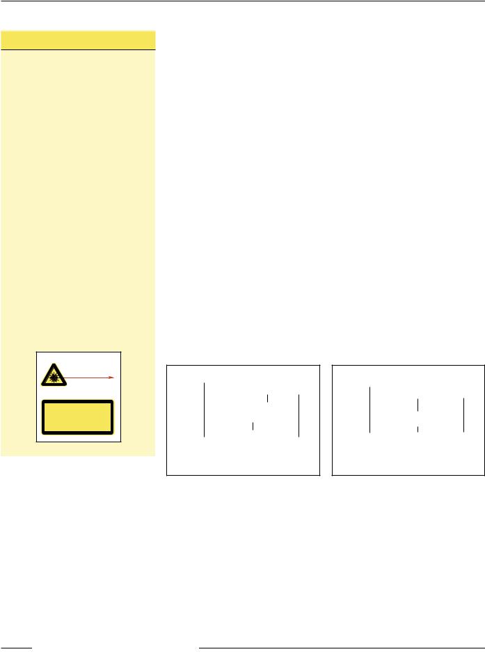
Teaching Discrete Limits for Background Suppresson
For some applications, ignoring objects beyond a certain distance may be required. To suppress the background, place a target object at the selected distance, and teach the position twice. The sensor’s discrete output will activate when an object is detected between the sensor’s minimum sensing distance and the taught position.
NOTE: The sensor allows for some forgiveness in this procedure. If the two limits are not exactly the same (but less than 20 mm apart), the sensor will put the set point at the “average” of the two limits.
Output 1 and Output 2 may be taught independent limits for background suppression (see Figure 3).
To set both outputs at exactly the same limits, set them simultaneously. This will result in complementary outputs (while one output is conducting, the other is not; see Figure 4). Hysteresis will be controlled by Output 1 and Output 2 will follow.
Output 1 |
|
|
|
|
|
|
|
|
|
|
|
|
|
|
|
|
|
|
|
|
Output 2 |
|
|
Teach |
|
|
|
|
|
|
Point 1 |
|
|
|
|
|
|
|
|
|
|
Near |
Teach |
Far |
||||
Point 2 |
||||||
Sensing |
|
|
|
Sensing |
||
Range |
|
|
|
Range |
||
Figure 3. Each output has its own limit for background suppression
Output 1 |
|
|
|
|
|
|
|
|
|
|
|
Output 2 |
|
|
|
|
|
|
|
|
|
||
|
|
Far |
|||
|
|
|
|
||
Near |
Teach |
||||
Sensing |
Point |
Sensing |
|||
Range |
|
|
Range |
||
Figure 4. The two outputs share identical limits for background suppression, but are complementary
Banner Engineering Corp. • Minneapolis, MN U.S.A.
www.bannerengineering.com • Tel: 763.544.3164 |
P/N 68503 rev. C |
3 |
|
L-GAGE® LT3 Long-Range Time-of-Flight Sensor – Two Discrete Outputs
Teaching Independent Limits for Either Output
Either output may be programmed first. |
|
|
|
|
|
|
||
|
|
|
|
|
||||
|
Output 1 |
|
|
|
|
|
|
|
|
Near |
|
Far |
|
||||
|
|
|
|
|
||||
|
|
|
Limit 1 |
|
Limit 1 |
|
||
|
|
|
|
|
|
|
||
|
Output 2 |
|
|
|
|
|
|
|
Near |
Far |
|
||||||
|
|
|
||||||
|
|
Limit 2 |
Limit 2 |
|
||||
|
|
|
|
|
|
|
|
|
Figure 5. Each output has its own near and far limits
Mode
Programming
First Limit
Teach
Teach |
Second Limit |
Program Second |
Output |
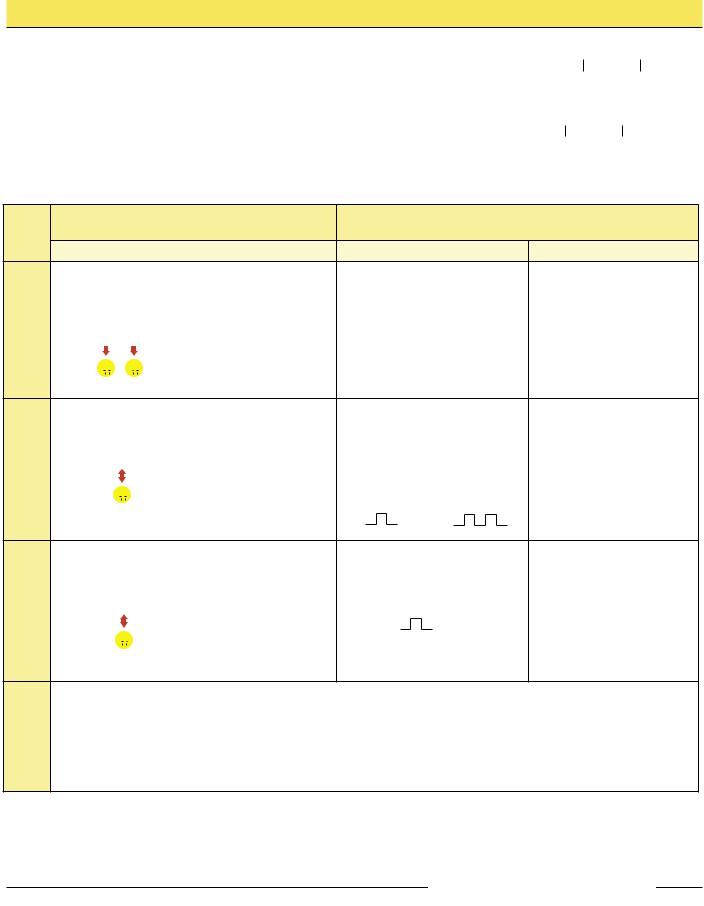
Push Button
0.04 sec. ≤ “click” ≤ 0.8 sec.
Procedure |
Result |
|||||||||||||
• Push and hold |
• Appropriate TEACH LED |
|||||||||||||
push button for |
turns ON |
|||||||||||||
desired output |
• Sensor is waiting for first |
|||||||||||||
> 2 seconds* |
limit |
|||||||||||||
|
|
|
|
|
|
or |
|
|||||||
D |
|
|
|
|
|
|
D |
|
|
|
|
|
|
|
• Position the target for |
• TEACH LED flashes |
|||||||||||||
the first limit** |
• Sensor learns first limit |
|||||||||||||
• “Click” the same push |
and waits for second limit |
|||||||||||||
button |
|
|
|
|
|
|
|
|
|
|
|
|
|
|
|
|
|
|
|
|
|
|
|
|
|||||
|
|
|
|
|
|
D |
|
|
|
|
|
|
D |
|
|
|
|
|
|
|
|
|
|
|
|
|
|
|
|
|
|
|
|
|
|
|
|
|
|
|
|
|
|
|
• Position the target for |
• TEACH LED goes OFF |
|||||||||||||
the second limit |
• Sensor learns second |
|||||||||||||
• “Click” the same push |
limit and returns |
|||||||||||||
button |
|
|
|
|
|
|
|
|
|
|
|
|
|
automatically to RUN |
|
|
|
|
|
|
|
|
|
|
|
|
|
|
mode |
|
|
|
|
|
|
|
|
|
||||||
|
|
|
|
|
|
D |
|
|
|
|
|
|
D |
|
|
|
|
|
|
|
|
|
|
|
|
|
|
|
|
|
|
|
|
|
|
|
|
|
|
|
|
|
|
|
|
|
|
|
|
|
|
|
|
|
|
|
|
|
|
Repeat for other output, if a second output is desired.
|
Remote Wire |
|
0.04 sec. ≤ T ≤ 0.8 sec. |
Procedure |
Result |
No action required
• Position the target for the first |
• Appropriate TEACH LED turns |
||
limit** |
|
|
ON, then flashes at 2 Hz |
|
|
|
• Sensor learns first limit and |
Output 1 |
|
Output 2 |
|
|
waits for second limit |
||
• Single-pulse |
|
• Double-pulse |
|
the remote |
|
the remote line |
|
line |
|
|
|
T |
|
T T T |
|
|
|
|
|
• Position the target for the second |
• Appropriate TEACH LED |
||
limit |
|
|
goes OFF |
• Single-pulse the remote line |
• Sensor learns second limit |
||
|
|
|
and returns automatically to |
|
T |
RUN mode |
|
|
|
||
*Sensor will return to RUN mode if first TEACH condition is not registered within 120 seconds.
**Press and hold the same push button (or hold the remote line high) > 2 seconds (before teaching the second limit) to exit PROGRAM mode without saving any changes. The sensor will revert to the last saved program.
Banner Engineering Corp. • Minneapolis, MN U.S.A.
4 |
P/N 68503 rev. C |
www.bannerengineering.com • Tel: 763.544.3164 |
|
 Loading...