


PresencePLUS P4
Table of contents
 Loading...
PresencePLUS
User's Manual
®
P4 AREA/AREA 1.3
Banner Engineering Corp.
P/N 125439 rev. D — 2009R2


Table of Contents
1. Product Support and Maintenance...................................................................7
1.1 Product Support......................................................................................................................7
1.2 Maintenance...........................................................................................................................8
2. System Description ...........................................................................................9
2.1 P4 Vision Sensors..................................................................................................................9
2.1.1 Typical P4 Vision Application........................................................................................9
2.1.2 PresencePLUS®P4 Components..............................................................................10
2.1.3 P4 Cable Connections................................................................................................11
2.2 Software Overview................................................................................................................12
2.2.1 Main Menu Toolbar ....................................................................................................13
2.2.2 Image Window............................................................................................................14
2.2.3 Navigation/Results Window........................................................................................15
2.2.4 Configuration Window................................................................................................17
2.2.5 Status Window............................................................................................................17
3. Getting Started.................................................................................................19
3.1 Installing the PresencePLUS Software.................................................................................19
3.1.1 Installing the Software................................................................................................19
3.1.2 Starting Up the Software............................................................................................19
3.2 Typical Setup and Startup Sequence...................................................................................24
3.3 Startup and Troubleshooting................................................................................................24
3.3.1 General Troubleshooting............................................................................................25
3.4 Setting Up Hardware Parameters.........................................................................................26
3.5 Building an Inspection...........................................................................................................26
4. Setup.................................................................................................................29
4.1 Setup Screen........................................................................................................................29
4.2 Capturing a Reference Image..............................................................................................29
4.3 Focus Tab.............................................................................................................................29
4.3.1 Reference Image Source...........................................................................................30
4.3.2 Focus Value................................................................................................................31
4.3.3 Auto Exposure............................................................................................................31
4.4 Trigger Tab............................................................................................................................32
4.4.1 Trigger Settings..........................................................................................................33
4.4.2 Resolution...................................................................................................................34
4.5 Advanced Tab.......................................................................................................................34
5. Tools Screen ....................................................................................................37
5.1 Overview...............................................................................................................................37
5.2 Typical Build/Modify Procedure............................................................................................38
5.2.1 Choosing a Tool..........................................................................................................38
5.2.2 Adding a Tool..............................................................................................................38
5.2.3 Adding a Test Tool......................................................................................................38
5.2.4 Renaming Tools..........................................................................................................38
5.2.5 Removing a Tool.........................................................................................................39
5.3 Quick Teach..........................................................................................................................39
5.4 Load Tab...............................................................................................................................39
iiiP/N 000000

7/2009PresencePLUS®P4 AREA/AREA 1.3
5.4.1 Flexible Inspection Loading........................................................................................40
5.4.2 Inspection Storage Capacity......................................................................................41
5.4.3 Opening an Inspection from the Sensor or a Library..................................................42
6. System Setup Window Overview....................................................................45
6.1 Sensor Select Tab.................................................................................................................46
6.1.1 Change Sensor IP Address........................................................................................48
6.1.2 PC (GUI) to Sensor Connection Setup.......................................................................49
6.1.3 IP Address History......................................................................................................50
6.2 Communication Tab..............................................................................................................51
6.2.1 Communication Setup................................................................................................52
6.2.2 Remote Command Channel Configuration ...............................................................56
6.2.3 PresencePLUS/Kawasaki Vision Guidance and Inspection.......................................65
6.2.4 Using Custom_ASCII to Communicate with an External Device Over Ethernet........81
6.3 P4 Input/Output Tab..............................................................................................................82
6.4 Strobe Tab............................................................................................................................84
6.4.1 Strobe Width...............................................................................................................84
6.4.2 Level...........................................................................................................................85
6.5 Units Tab...............................................................................................................................85
6.6 Reset Tab..............................................................................................................................86
6.7 Start-Up Inspection Tab........................................................................................................87
6.8 NTSC Tab.............................................................................................................................89
6.9 Language Tab.......................................................................................................................90
6.10 Tools Configuration.............................................................................................................91
6.10.1 Standard Mode.........................................................................................................92
6.10.2 Enhanced Mode.......................................................................................................92
6.10.3 Custom Mode...........................................................................................................92
6.10.4 Tool Licensing...........................................................................................................92
7. PresencePLUS Software Tools.......................................................................95
7.1 ROI Types.............................................................................................................................95
7.1.1 Linear ROI..................................................................................................................95
7.1.2 Area ROI.....................................................................................................................95
7.1.3 Search ROI.................................................................................................................96
7.2 Location Tools.......................................................................................................................96
7.2.1 Locate Tool.................................................................................................................96
7.3 Vision Gray Scale Tools......................................................................................................103
7.3.1 Average Gray Scale Tool..........................................................................................104
7.3.2 Blob Detect Tool.......................................................................................................107
7.4 Analysis Tools.....................................................................................................................119
7.4.1 Communication Tool.................................................................................................120
7.4.2 Math Tool..................................................................................................................136
7.4.3 Measure Tool............................................................................................................141
7.4.4 Test Tool...................................................................................................................162
8. Communication Tool Setup...........................................................................183
8.1 Ethernet Connection...........................................................................................................183
8.2 Serial Connection...............................................................................................................185
8.3 Overview of Testing the Communication Tool.....................................................................186
8.4 Detailed Steps for Testing the Communication Tool...........................................................187
8.4.1 Testing Ethernet Communications............................................................................187
8.4.2 Testing Serial Communications................................................................................187
8.5 Troubleshooting Ethernet Connections..............................................................................188
8.6 Troubleshooting Serial Connections...................................................................................188
P/N 000000iv

PresencePLUS®P4 AREA/AREA 1.37/2009
8.7 Remote Command Channel Configuration ........................................................................189
8.7.1 Remote Command Set ............................................................................................189
8.7.2 RCC Return Values..................................................................................................192
8.7.3 Frame Tag Numbers ................................................................................................193
8.7.4 Command Processing .............................................................................................194
8.7.5 RCC Log ..................................................................................................................194
8.7.6 Frame and Field Delimiters......................................................................................195
9. Teach...............................................................................................................197
9.1 Quick Teach........................................................................................................................197
9.2 Teach..................................................................................................................................197
9.3 Teach Screen......................................................................................................................198
9.3.1 Teaching an Inspection.............................................................................................198
9.4 Remote Teach.....................................................................................................................200
9.4.1 Understanding Remote Teach..................................................................................200
9.4.2 Remotely Teaching a Tool........................................................................................201
9.4.3 Timing Sequence......................................................................................................201
9.4.4 Remote Teach Results.............................................................................................202
10. Run Screen...................................................................................................203
10.1 Selected Inspection..........................................................................................................204
10.2 Display..............................................................................................................................204
10.3 Capture Control................................................................................................................205
10.4 Results..............................................................................................................................205
10.5 Inputs................................................................................................................................206
10.6 Outputs.............................................................................................................................206
10.7 Product Select..................................................................................................................207
10.8 System..............................................................................................................................207
10.9 Start/Stop..........................................................................................................................207
10.10 Select Tab.......................................................................................................................207
10.11 Log Tab...........................................................................................................................209
10.12 Run Results....................................................................................................................211
10.13 Run Player/Recorder......................................................................................................213
10.13.1 Record..................................................................................................................215
10.13.2 Playback...............................................................................................................217
11. Product Change............................................................................................221
11.1 Product Change Specifications.........................................................................................221
11.2 Product Select Input Specifications..................................................................................222
12. P4 Product Change and Product Select Timing........................................223
12.1 One Pulse Set Overview...................................................................................................223
12.1.1 Product Select in One-Pulse Configuration............................................................224
12.2 Three Pulse Set Overview................................................................................................225
12.2.1 Product Select in Three-Pulse Configuration.........................................................225
13. Saving Inspections.......................................................................................227
13.1 Saving Inspections to a Vision Sensor.............................................................................228
13.2 Saving Inspections to a PC or Network Drive...................................................................230
14. Backing Up and Restoring Vision Sensor Data.........................................231
14.1 Backing up Vision Sensor Data........................................................................................231
14.2 Restoring Vision Sensor Data...........................................................................................235
vP/N 000000

7/2009PresencePLUS®P4 AREA/AREA 1.3
15. Dimensions and Specifications..................................................................239
15.1 Sensor Dimensions...........................................................................................................239
15.1.1 Right-Angle Sensor Dimensions............................................................................239
15.1.2 Right-Angle Sensor Mounting Bracket Dimensions...............................................239
15.1.3 In-Line Sensor Dimensions....................................................................................240
15.1.4 In-Line Sensor Mounting Bracket Dimensions.......................................................240
15.2 Sensor Specifications.......................................................................................................241
15.3 Monitor Specifications - 9" CRT........................................................................................243
15.4 Monitor Specifications - Flat Panel 8" LCD Color.............................................................243
15.5 Ethernet Communication Specifications...........................................................................244
15.6 Serial Port Communication Specifications........................................................................245
..............................................................................................................................247
P/N 000000vi
Product Support and Maintenance
This section provides general Banner resources and specific documentation for installers and operators of this
PresencePLUS Vision Sensor.
Attention: Not to be Used for Personal Protection.
Never use these products as sensing devices for personel protection. Doing so could lead to serious injury
or death.
These sensors do NOT include the self-checking redundant circuitry necessary to allow their use in personnel
safety applications. A sensor failure or malfunction can cause either an energized or de-energized sensor output
condition. Consult your current Banner Safety Products catalog for safety products which meet OSHA, ANSI, and
IEC standards for personnel protection.
1.1 Product Support
1
Banner provides the following resources for quickly setting up and operating the sensor.
Documentation
Online Help
The PresencePLUS online help is available from the from the Help menu item within the PresencePLUS
software. You can also get targeted help while on any system tab or dialog by pressing the <F1> key.
PDF Documentation
The PresencePLUS Sensor documentation is available in a convenient printable format (PDF) on the installation
CD or on the Banner Web site
Banner Website
The most current PresencePLUS information, documentation, and software updates are available at the
following Banner website page:
www.bannerengineering.com
Warranty Service
The PresencePLUS Vision Sensor is designed for reliability. Do not open the housing; it contains no
field-replaceable components. If repair is necessary, do not attempt to repair the sensor yourself; return the
unit to the factory. Should it become necessary to return a sensor to the factory, please do the following:
1. Contact the Banner Factory Application Engineering group at the address or numbers listed below.
They will attempt to trouble shoot the system from your description of the problem. If they conclude
that a component is defective, they will issue an RMA (Return Merchandise Authorization) number
for your paperwork and give you the proper shipping address.
P/N 000000
Tel: 763.544.3164
7Banner Engineering Corp. - Minneapolis, MN USA - www.bannerengineering.com

7/2009Product Support and Maintenance
2. Pack the sensor carefully. Damage which occurs during return shipping is not covered by warranty.
Factory Support
Call, e-mail, fax, or write your local Banner representative or a Banner Applications Engineer for support.
Applications Engineers are available from 8:00 A.M. to 5:00 P.M. Central Time, Monday through Friday,
excluding holidays.
Phone
Local: 763.544.3164
Toll Free: 1.888.3.SENSOR (1.888.373.6767)
763.544.3213Fax
sensors@bannerengineering.comE-mail
Address
To help Banner better assist you, be ready to provide the following information:
Banner Engineering Corp.
9714 10th Avenue North, Minneapolis, MN 55441 USA
• PresencePLUS software version (to find version number, click Help in the Main Menu toolbar and
choose About)
• Operating system of your PC
• Sensor Model Number and Date Code. Model Number is on top of Sensor, Date Code is either on
the bottom or the side
• Exact wording of any messages that appeared on your screen
• A description of what you were doing and what happened
• A description of how you tried to solve the problem
1.2 Maintenance
Maintenance tasks include keeping the hardware free of dust and dirt and possibly updating the PresencePLUS
software as new versions become available.
Cleaning the Sensor
Regularly remove any dust or dirt from the Sensor using a soft cloth. If needed, slightly dampen the cloth with
a weak solution of neutral detergent. Avoid getting dirt on the imager (the area behind the lens). If the imager
is dirty, use anti-static compressed air to blow off the dust.
Cleaning the Lens
Regularly remove dust, dirt, or fingerprints from the lens. Use anti-static compressed air to blow off dust. If
necessary, use a lens cloth and lens cleaner or window cleaner to wipe off remaining debris.
Do not use any other chemicals for cleaning.
Updating the PresencePLUS Software
The current version of PresencePLUS software is available for download from the Banner website. See Banner
Website for the software downloads link.
8
Tel: 763.544.3164
P/N 000000Banner Engineering Corp. - Minneapolis, MN USA - www.bannerengineering.com

2
System Description
The PresencePLUS ProII and P4 sensor families are easy-to-use camera systems with advanced visual inspection
capability. With minimal knowledge of vision systems, a user can quickly set up a PresencePLUS ProII or P4 and
run an inspection that tests products accurately, rejecting bad products on a production line.
Inspections are set up using a personal computer (PC). A digital camera inside the Vision sensor captures images,
and the sensor software analyzes the images using one or more Vision tools to pass or fail the product. The PC is
not required for running inspections after the inspection files have been stored in the sensor’s memory.
Inspection setup involves focusing the camera and selecting the appropriate Location, Vision, and Analysis tools.
The full range of inspection tolerances can be established either automatically or manually. The automatic Teach
function eliminates the iterative process of determining correct tolerances.
The PresencePLUS ProII and P4 Sensor families accommodate both translational and rotational variation. Parts
moving down a production line or web need not be oriented in exactly the same way.
The Sensor is easy to operate, with both basic and advanced options. New users can follow the guided Setup
sequence. Advanced users can override automatic settings and create highly customized inspections.
2.1 P4 Vision Sensors
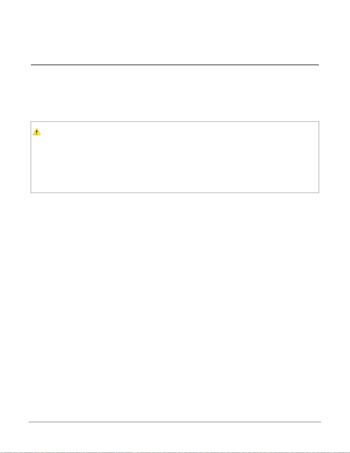
2.1.1 Typical P4 Vision Application
A typical PresencePLUS P4 application is shown below.
P/N 000000
Tel: 763.544.3164
9Banner Engineering Corp. - Minneapolis, MN USA - www.bannerengineering.com
7/2009System Description
In the application shown above, as each plastic formed part comes past the Vision sensor, an inspection is
performed. If the part is not shaped correctly as shown here, the inspection fails.
2.1.2 PresencePLUS®P4 Components
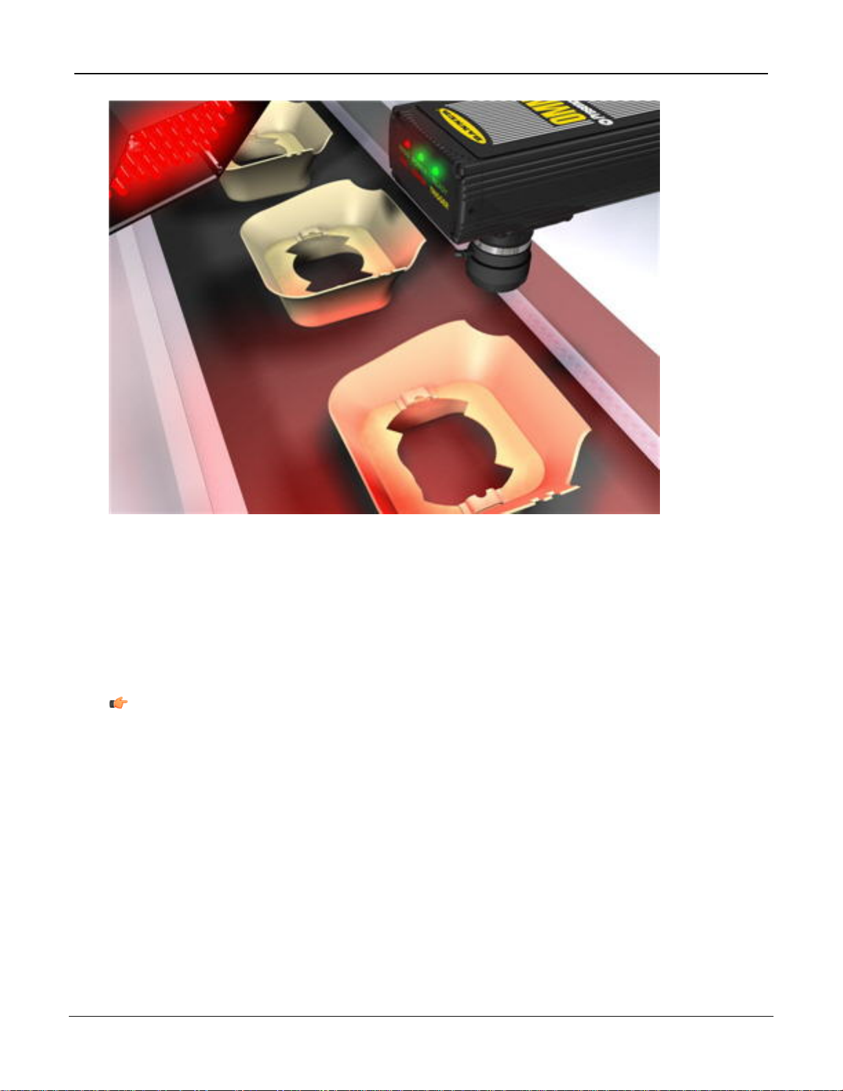
The PresencePLUS P4 system consists of the Sensor and a PC with PresencePLUS software and the
appropriate connections. The Sensor requires lighting and a trigger device, and an optional video monitor can
be connected.
Note: The trigger device can be any 10-30V dc photoelectric sensor (PNP or NPN) or a device with a
similar output.
10
Tel: 763.544.3164
P/N 000000Banner Engineering Corp. - Minneapolis, MN USA - www.bannerengineering.com
2.1.3 P4 Cable Connections
System Description7/2009
or Switch
STP07 — 2.1 m (7')
P/N 000000
Note: The sensor power must be 24V dc ± 10% if a light source is powered by the sensor.
Monitor Cable (to Video Monitor, optional)Crossover Ethernet Cable (to PC Ethernet Port)*
BNC06 —2 m (6')STPX07 — 2.1 m (7')
BNC15 — 5 m (15')STPX25 — 7.6 m (25')
BNC30 — 9 m (30')or
Serial Cable (to PC serial Port)*Standard Ethernet Cable (to PC via Network Hub
DB9P06 — 2 m (6')
DB9P15 — 5 m (15')
11Banner Engineering Corp. - Minneapolis, MN USA - www.bannerengineering.com
Tel: 763.544.3164
7/2009System Description
STP25 — 7.6 m (25') DB9P30 — 9 m (30')
*The Sensor can be connected to the PC via a serial cable or an Ethernet network; Ethernet provides faster
communication.
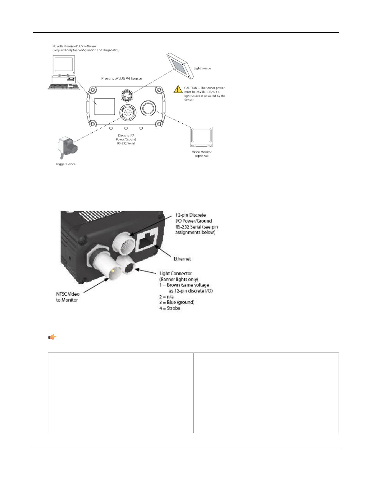
DirectionDescriptionWire ColorPin #
OutputRS-232 TX**Yellow1
InputRemote TeachGray2
InputProduct ChangeOrange3
InputExternal TriggerPink4
In/OutDiscrete I/O #1Black5
In/OutDiscrete I/O #2Red6
In/OutDiscrete I/O #3White7
In/OutDiscrete I/O #4Light Blue8
InputRS-232 RX**Violet9
OutputRS-232 Signal Ground**Green10
** These three wires make up the RS-232 serial connection.
Note: All unused inputs and outputs should be connected to ground if configured as PNP, and
connected to +24V dc if configured as NPN. Serial input pins should be connected to ground.
2.2 Software Overview
The PresencePLUS application window is shown below.
InputCommon (Signal Ground)Blue11
Input10-30V dcBrown12
12
Tel: 763.544.3164
P/N 000000Banner Engineering Corp. - Minneapolis, MN USA - www.bannerengineering.com
System Description7/2009
2.2.1 Main Menu Toolbar
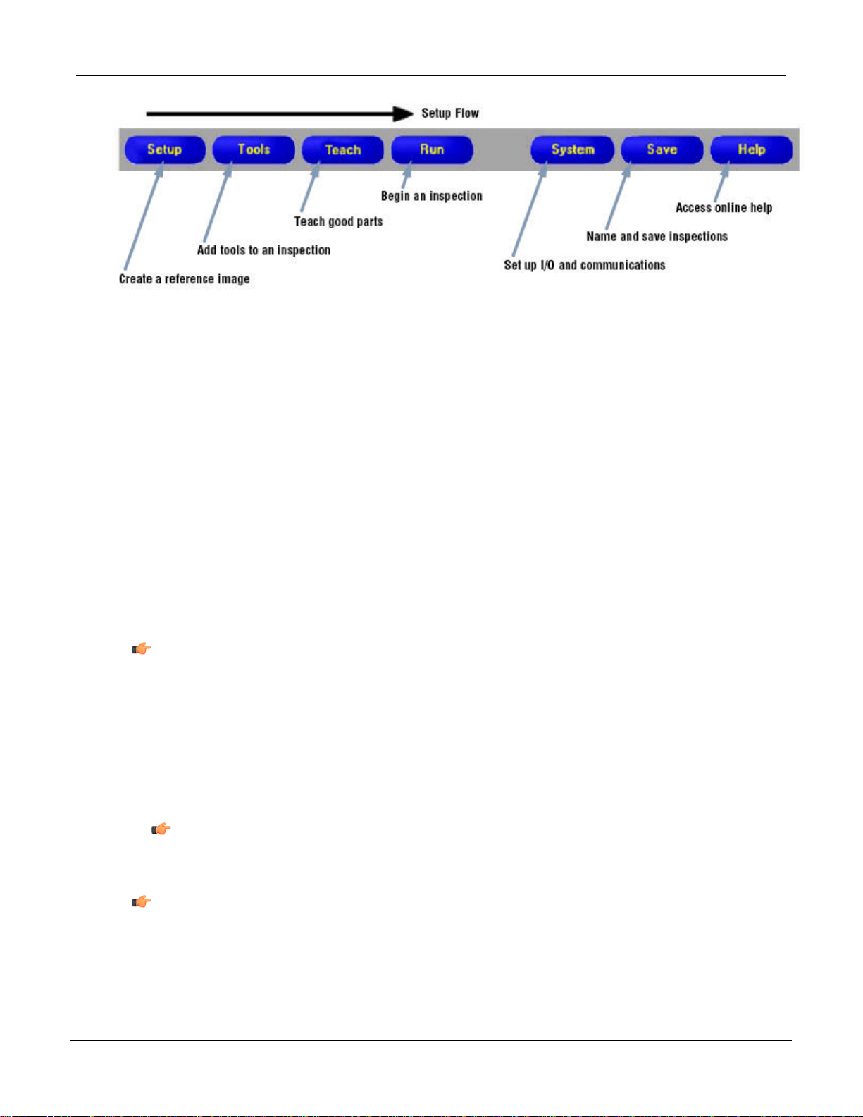
Use the Main Menu toolbar to navigate between the Sensor options. Proceeding from left to right, the buttons
in the Main Menu toolbar step through the process of creating and controlling an inspection. Each button is
explained in the illustration below and in the table that follows.
The following table describes the screen associated with each button in the Main Menu.
Inspection-Specific Screens
Setup
Tools
Teach
System
Set up the camera, lens, trigger, and lighting to acquire images. Create a reference image
to be used later.
Add tools to an inspection. Build the inspection from scratch, or load tools from a previous
inspection file saved on the controller or a PC.
Teach the Sensor good products. This screen automatically configures the parameters
chosen in the Tools screen.
Choose which inspection file the Sensor will run, and view the results of the inspectionRun
System-Wide Screens
Set up the discrete inputs and outputs and communication configuration. This screen also
has the Sensor diagnostic tools.
P/N 000000
Name the current inspection files and save them to the controller or a PC for future use.Save
13Banner Engineering Corp. - Minneapolis, MN USA - www.bannerengineering.com
Tel: 763.544.3164
Inspection-Specific Screens
Call the Help window or the About window.Help
2.2.2 Image Window
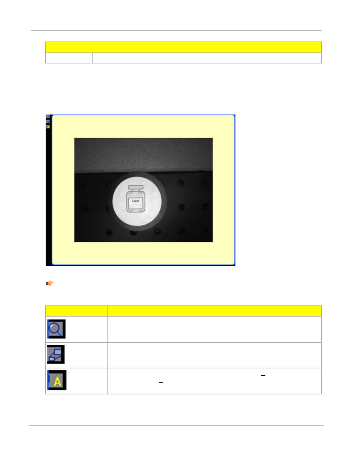
The Image window, on the left side of the screen, displays images acquired from the camera or the reference
image that is set for the current inspection. The toolbar buttons in the Image window are explained below.
7/2009System Description
14
Note: The reference image is used as a template for developing an inspection; it establishes
the initial values for the Vision tools. The reference image also is used by Quick Teach.
DescriptionIcon
Zoom -- toggles zoom control. When enabled, click on the image window to zoom
in and right-click to zoom out. This button is active when an image is displayed in
the Image window.
Expand Image -- toggles the size of the Image window between maximum and
minimum.
Selected ROI / ALL ROIs -- toggles between the currently S elected Region of
Interest (ROI) and A ll ROIs.
P/N 000000Banner Engineering Corp. - Minneapolis, MN USA - www.bannerengineering.com
Tel: 763.544.3164
System Description7/2009
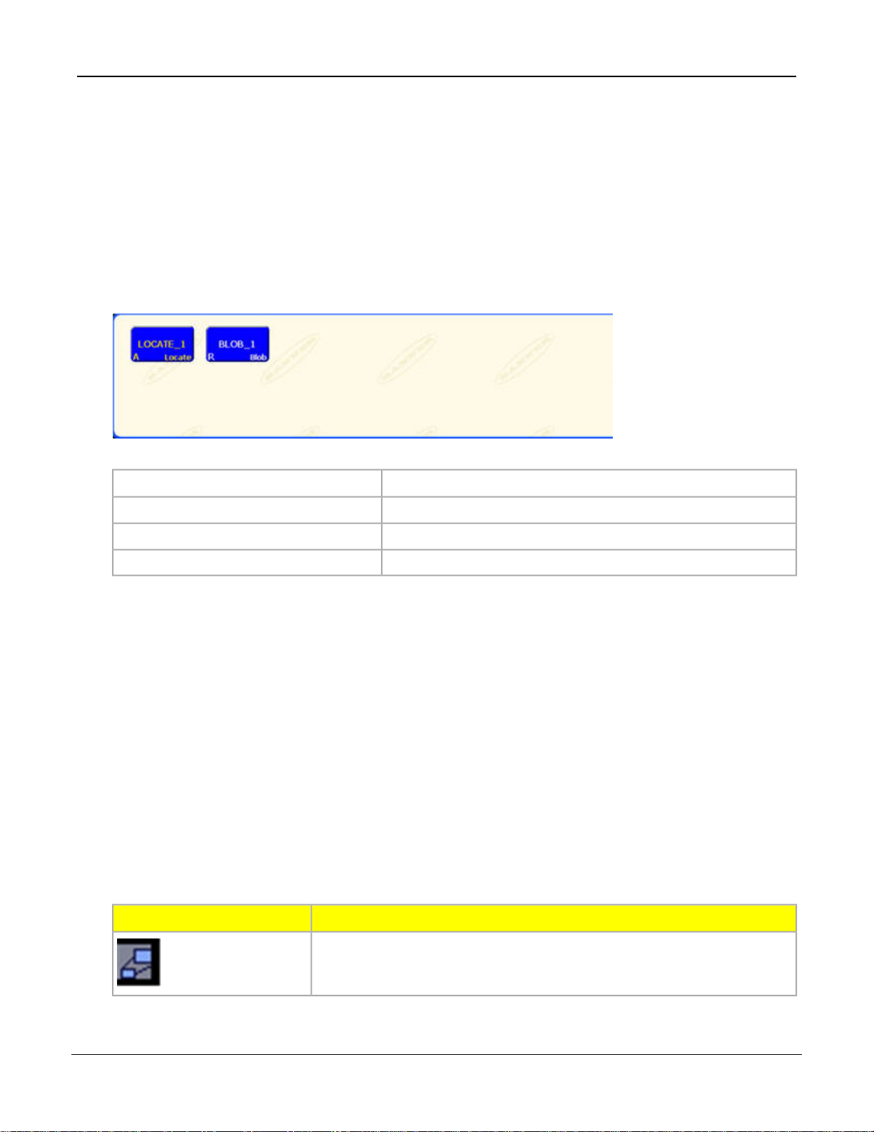
2.2.3 Navigation/Results Window
The Navigation/Results window, at the bottom of the screen, displays tool navigation buttons or inspection
results files.
Navigation Buttons
Clicking on the Tools button in the Main Menu toolbar brings up the tool navigation buttons in the
Navigation/Results window. When setting up or using tools, click on any tool navigation button to get the
corresponding tab in the Configuration window.
Tool nameLOCATE_1 (or BLOB_1)
AbsoluteA
RelativeR
Tool typeLocate (or Blob)
Absolute and Relative Tools
An absolute tool’s Region of Interest (ROI) does not move in the image window. A relative tool shifts the ROI
from the previous tool, relative to the position of the part.
The Location tools (for example, Locate) track parts in the Image window, and the Vision tools that follow (for
example, Average Gray Scale and Blob Detect) are relative. A Vision tool that precedes all Location tools will
be absolute. Rules governing whether a tool is absolute or relative are as follows:
• The first Location tool is always absolute.
• All tools following a Location tool are relative to that tool unless they are made absolute themselves, in which
case the chain is broken, and a new chain is started.
• For a Vision tool to be absolute, it must be placed before any Location tools.
Navigation/Results Toolbar Buttons
Using the Navigation/Results toolbar buttons, the Navigation/Results window size can be set, and tools can
be deleted.
P/N 000000
DescriptionIcon
Expand Results -- toggles the size of the Navigation/Results window between
maximum and minimum.
15Banner Engineering Corp. - Minneapolis, MN USA - www.bannerengineering.com
Tel: 763.544.3164
7/2009System Description
DescriptionIcon
Delete Selected Tool -- deletes the selected tool from the current inspection.
Delete Selected Tools -- deletes the selected tool and all the tools to the
right of the selected tool.
Copy Selected Tool -- clones the selected tool.
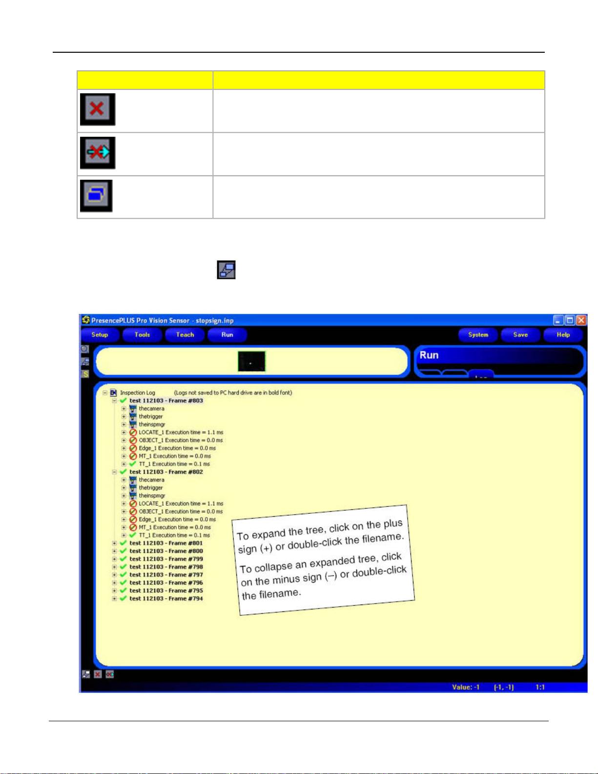
Expand Button
Clicking on the Expand button ( ) toggles the size of the Navigation/Results window to accommodate an
expanded list of inspection results files, as shown below.
16
Tel: 763.544.3164
P/N 000000Banner Engineering Corp. - Minneapolis, MN USA - www.bannerengineering.com
System Description7/2009
2.2.4 Configuration Window
The Configuration window, on the right side of the screen, displays the currently selected options with multiple
tabs. Clicking the Setup, Tools, Teach, Run, System, Save, or Help buttons on the Main Menu toolbar changes
the contents of the Configuration window accordingly.
2.2.5 Status Window
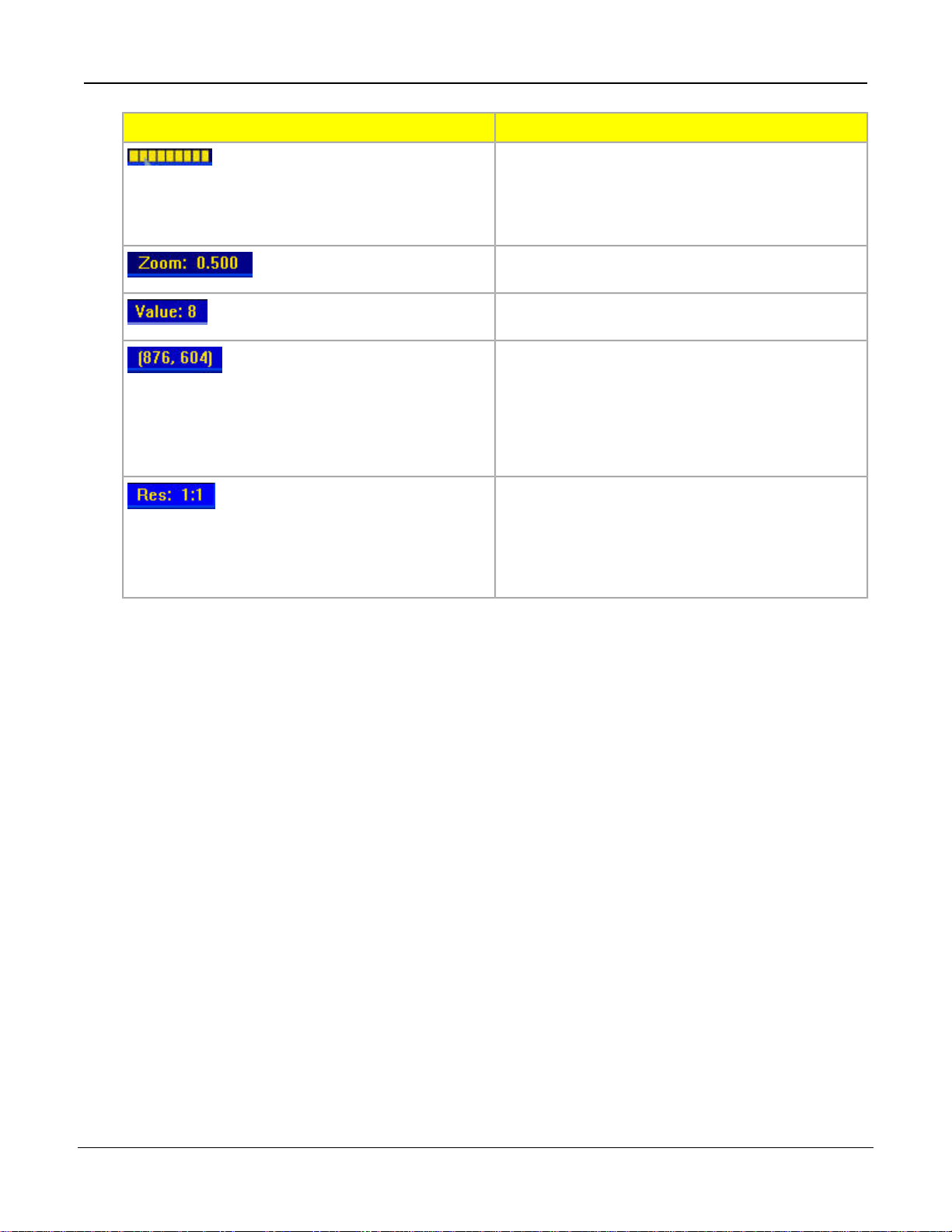
The Status window, shown below, provides the following Sensor feedback.
The following table provides descriptions of each region in the Status window:
DescriptionRegion
Connection info -- current sensor to which the PC is
connected.
P/N 000000
Tel: 763.544.3164
17Banner Engineering Corp. - Minneapolis, MN USA - www.bannerengineering.com
7/2009System Description
DescriptionRegion
Image update completion -- progress bar shows
relative image update completion when an image is
being transferred from the camera to the PC (this
flickers, and is next to Connection: Sensor
192.168.0.1).
Current zoom value - works with the Zoom icon
(magnifying glass).
Current grayscale value -- the 0-255 gray scale value
of the pixel under the cursor.
Cursor position -- displays the x, y coordinates of the
pixel under the cursor relative to the upper-left corner
(origin, which is 0,0) of the field of view. Note that you
must have the mouse pointer hovering over the image
to get this information, otherwise, it displays
(-1,-1).
Current image display resolution -- displays the
user-specified value, which can be from 1:1 to 64:1.
Note that this does not affect how the sensor operates;
it only affects sensor-to-GUI image communication
speed, and is more useful when using Serial
communication.
18
Tel: 763.544.3164
P/N 000000Banner Engineering Corp. - Minneapolis, MN USA - www.bannerengineering.com

3
Getting Started
This section begins with some Vision basics, then provides a brief overview of how to install the software, and the
general steps to creating an inspection.
3.1 Installing the PresencePLUS Software
The PresencePLUS software CD includes the sensor software and this documentation.
3.1.1 Installing the Software
To install the PresencePLUS software:
1. Close all active programs.
2.
Make sure that no previous installations of PresencePLUS are installed.
3.
Insert the PresencePLUS CD into the CD ROM drive of the personal computer. If you have
auto-start enabled, the CD should automatically start. If it doesn't start --
a. Double-click on the My Computer icon on the desktop.
b. Double-click on the CD Drive in the list that appears.
c. Double-click on the PresencePLUS autorun file.
4. When the Install screen appears, click PresencePLUS PC Software.
5. Follow the instructions on the screen.
6. When the installation completes, reboot the PC.
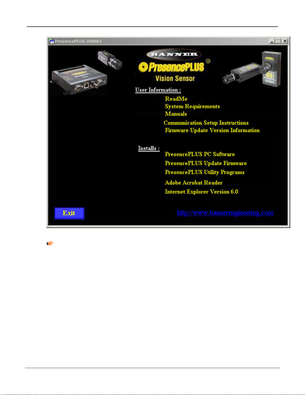
3.1.2 Starting Up the Software
1. Power up the PC.
2.
Install the software if it has not been installed. The installation screen of the PresencePLUS Pro
software CD is shown below.
P/N 000000
Tel: 763.544.3164
19Banner Engineering Corp. - Minneapolis, MN USA - www.bannerengineering.com
7/2009Getting Started
Note: The following instructions assume you are installing the software on Windows XP.
3. If using an Ethernet communication cable, configure the IP address as follows:
a. Open Network Properties on the PC (right-click on the Network Neighborhood icon).
20
Tel: 763.544.3164
P/N 000000Banner Engineering Corp. - Minneapolis, MN USA - www.bannerengineering.com
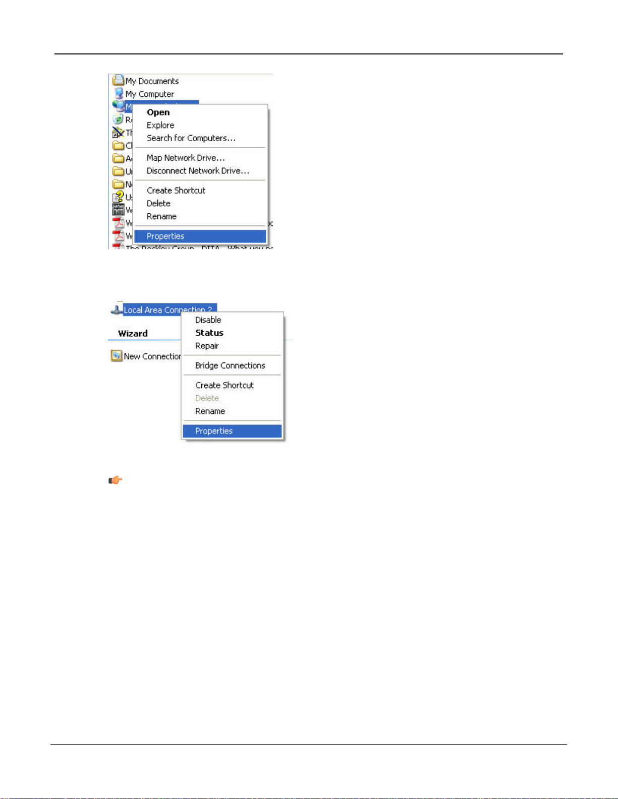
b. On the Local Area Connection, right-click on Properties.
Getting Started7/2009
P/N 000000
Note: The PC in the example above has a second network card which is used to connect
to the camera so it is using Local Area Connection 2.
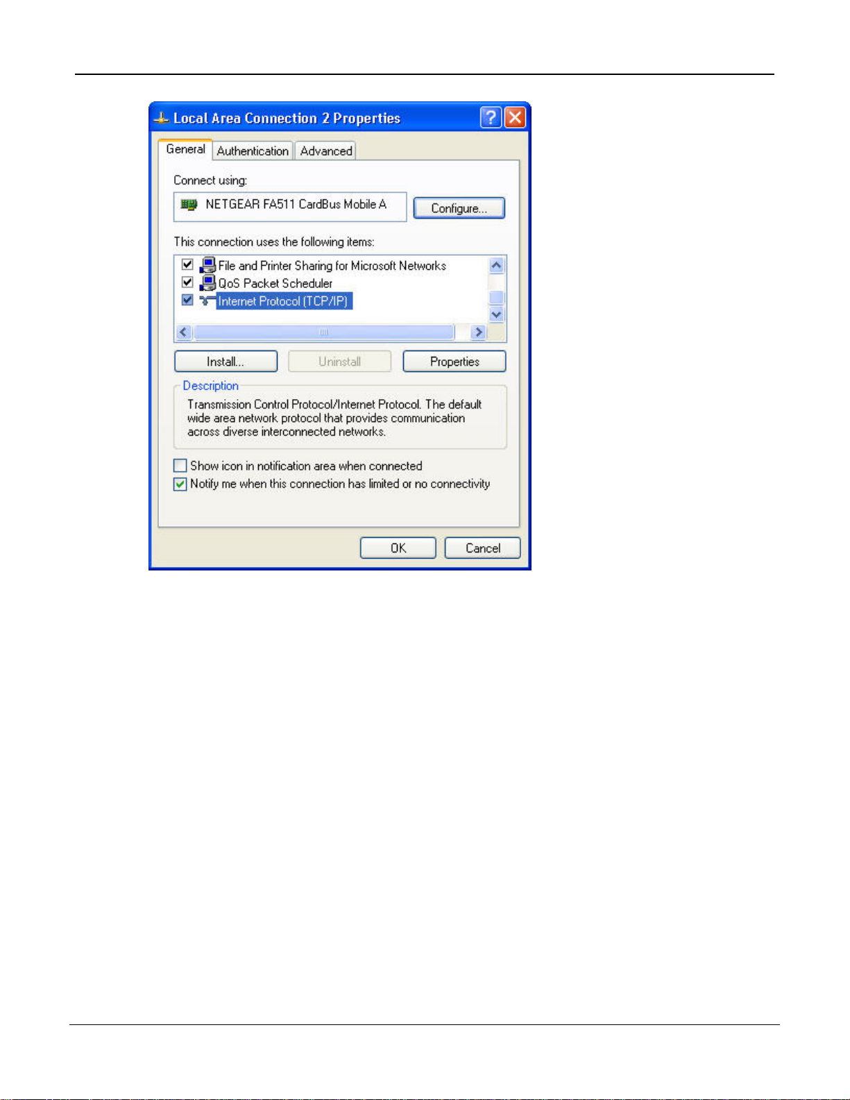
c. In the dialog, click on Internet Protocol (TCP/IP) and click the Properties button.
21Banner Engineering Corp. - Minneapolis, MN USA - www.bannerengineering.com
Tel: 763.544.3164
7/2009Getting Started
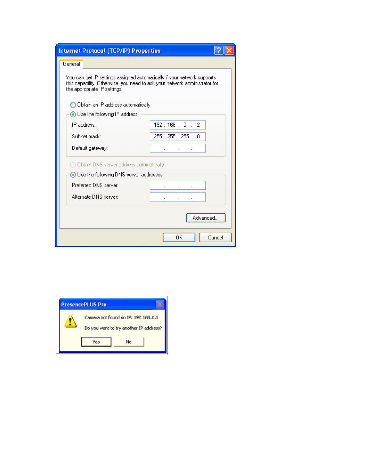
4. In the Internet Protocol (TCP/IP) Properties dialog, select Use the following IP address and
make sure that the the IP address is 192.168.0.2, and the subnet mask is 255.255.255.0.
22
Tel: 763.544.3164
P/N 000000Banner Engineering Corp. - Minneapolis, MN USA - www.bannerengineering.com
Getting Started7/2009
5. Start the sofware.
6. Upon initial startup, the software communication is not configured, and the following error message
is displayed.
7. Click Yes to open the Communication screen.
8. Establish communications as follows:
Ethernet
Connection
1. When the software is started for the first time, the IP address is "Localhost."
Choose Ethernet (RJ 45).
2. Change the IP address to 192.168.0.1 (default IP address of the sensor).
3. Click OK.
P/N 000000
Tel: 763.544.3164
23Banner Engineering Corp. - Minneapolis, MN USA - www.bannerengineering.com
3.2 Typical Setup and Startup Sequence
The following subsections proceed through a typical Sensor setup and startup sequence
1. Connect and power up the hardware.
2. Start up the software.
3. Set up hardware parameters.
4. Build and run an inspection.
7/2009Getting Started
3.3 Startup and Troubleshooting
The following explains how to verify connections and start the PresencePLUS software.
1. Verify cable connections.
• The sensor is connected to a PC with an Ethernet crossover cable ofr a serial cable.
• The monitor, if used, is connected to the sensor's video port.
2. Thread the lens onto the sensor.
3. Verify electrical connections.
• +V is connected to Pin 12, brown were, 10-30V dc (24V dc ± 10% if a light is powered by the
sensor).
• -V is connected to Pin 11, blue wire (dc common).
• The trigger device is connected to Pin 4 (pink wire, Trigger In).
• Any additional connections are made as required.
4. Verify power. Ensure that the sensor is powered by 10-30V dc (24V dc ± 10% if a light is powered
by the sensor).
5. Verify PC configuration.
• Ethernet connection: IP address of PC is 192.168.0.2.
• Serial connection: A dial-up network has been established, and the network is a point-to-point
protocol (PPP).
6. Power up the hardware and verify that the Error LED turns off.
24
Tel: 763.544.3164
P/N 000000Banner Engineering Corp. - Minneapolis, MN USA - www.bannerengineering.com

Getting Started7/2009
During powerup, all the sensor LEDs illuminate for 15 to 20 seconds.•
• After the Red Error LED turns OFF, verify that the Green power LED is flashing.
7. Launch the Software.
• Click Start > PresencePLUS to start the program.
• If the sensor has a different IP address than the default address (192.168.0.1), or if it is connected
through a serial connection, the following error message will display:
Sensor not found on specified IP address 192.168.0.1.
Do you want to try another IP address?
• Click Yes to access the System Setup window.
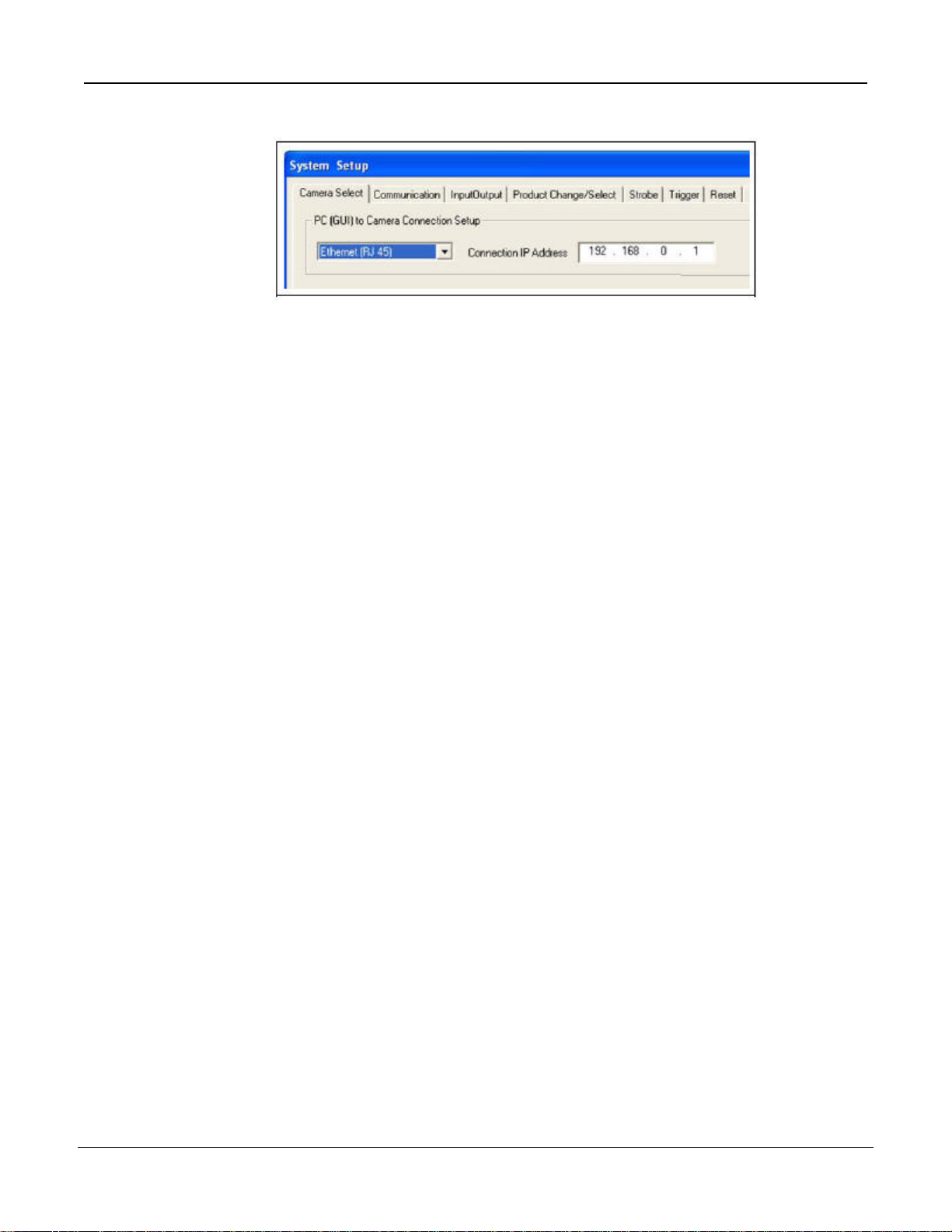
• Click on the Sensor select tab, and change the conection setup as follows:
Ethernet Connection --
1. Select Ethernet (RJ45) in the drop-down menu.
2. Change the IP address to the address of the sensor to which the PC is connected.
3. Click OK.
Serial Connection --
1. Select PC Serial in the drop-down menu.
2. Click OK.
3.3.1 General Troubleshooting
The following table describes solutions to the most common problems in using the PresencePLUS software.
For further assistance, contact Banner Engineering.
Cause/SolutionProblem
• Green Power LED on sensor is not ON.
• Interface cannot connect to the sensor.
• No image on the monitor.
• No image on PC or monitor.
• Green Ready LED on sensor is OFF.
• The software seems to be working correctly, but the
image is missing.
• Error message "Failed to capture a full-resolution
image. Please try again."
• Image is frozen on the PC and monitor.
• Green Ready LED on sensor is OFF
Sensor not getting enough power.
• Check the connection to the power supply.
Run display set to "None"
• Ensure that the sensor is receiving trigger signals.
Sensor not receiving triggers
• If the connections are secure, call a Banner
Applications Engineer.
Software restart needed or there are loose
connections.
• Restart the PresencePLUS software.
• Check all connections.
• If a software restart does not correct the problem and
the connections are secure, call a Banner
Applications Engineer.
P/N 000000
Tel: 763.544.3164
25Banner Engineering Corp. - Minneapolis, MN USA - www.bannerengineering.com

7/2009Getting Started
Cause/SolutionProblem
• Error message "Failed to capture a full-resolution
image. Please try again." • Reconnect the cable.
• •Image is frozen on PC, but image on monitor updates
properly.Image is frozen on PC, but image on monitor
updates properly.
• Indicator lights on RJ-45 port are OFF.
• Focus number does not update.
• QuickStart fails.
• Errors when saving inspections to the sensor.
Error code is displayed on PC.
Ethernet connection lost.
Check the cable for breaks, then power down and
back up.
• Replace the cable.
• Attempt to close and reopen PresencePLUS
software.
• If none of these actions fix the problem, call a Banner
Applications Engineer.
FTP communications is blocked.
• Disable TCP/IP Firewall software on the PC.
•• A list of error codes and potential causes and
solutions are available in the main help.
3.4 Setting Up Hardware Parameters
If the Sensor is being run for the first time, or if changes have been made to the hardware, then you
may need to set or modify hardware parameters.
1. Click on System in the Main Menu toolbar.
2. Configure the Trigger parameter according to the trigger device being used. For example, if using
the QS18V6ND as the trigger device, then select NPN.
3. Configure the six discrete inputs/outputs.
4. If the controller triggers a strobe light source, set the strobe trigger options.
5. If using the product select, configure the product select and product change lines to be NPN or
PNP as required.
6. Click on Setup in the Main Menu toolbar, select Trigger tab, and configure the remaining
parameters:
• Polarity
• Minimum Trigger Width
• Trigger delay
• Trigger Divide
3.5 Building an Inspection
The automatic screen sequence starts with the Setup screen, hich results from the first button (Setup) in the
Main Menu toolbar. Subsequent screens are shown below in the Main Menu toolbar layout.
26
Tel: 763.544.3164
P/N 000000Banner Engineering Corp. - Minneapolis, MN USA - www.bannerengineering.com
1. Setup screen:
a. Set up the camera, lens, and lighting.
b. Choose trigger option Continuous for a live image.
c. Click Auto-exposure to adjust the image brightness.
d. Focus the lens by turning the lens focusing ring until the focus value is maximized.
e. When the desired image is shown, click Next to proceed to the Tools screen.
2. Tools screen:
Getting Started7/2009
a. Add Location tool(s) to find the target to adjust the Regions of Interest (ROI) for translational and rotational
changes.
b. Required: Add Vision tool(s) to inspect the part.
c. Add Measure tools(s) to create distance measurements from points found.
d. Required: Add Test tool(s) to set the Pass/Fail criteria (Vision and Measure tools are inputs to the Test
tool).
e. Click Quick Teach to automatically set all the selected parameters in the Test tool and to proceed to
the Run screen, or click Next to proceed to the Teach screen and to teach a sample set of good products.
Note: To keep specific, user-defined parameters in a Test tool, skip Teach and go directly to Run.
3. Teach screen:
The Teach screen automatically configures the parameters chosen in the Tools screen.
a. Chooose the sample size.
b. Click Start.
c. Trigger the controller with the external trigger device.
d. Click Stop.
Note: Before entering Run, save inspection file to one of the memory locations on the controller.
e. Click Next to proceed to the Run screen.
4. Run screen:
P/N 000000
Note: Save a backup copy of the inspection to the host PC.
Select an inspection fo run, and review the results of the inspection.
27Banner Engineering Corp. - Minneapolis, MN USA - www.bannerengineering.com
Tel: 763.544.3164

To select an inspection (in the Select tab), enable Software Override, and select the inspection file from
•
the list of stored inspections on the camera.
• An alternate method is to use Hardware input to select an inspection via discrete inputs to the controller.
5. Begin inspection:
To begin inspecting, click the Start button in the Run screen.
7/2009Getting Started
28
Tel: 763.544.3164
P/N 000000Banner Engineering Corp. - Minneapolis, MN USA - www.bannerengineering.com

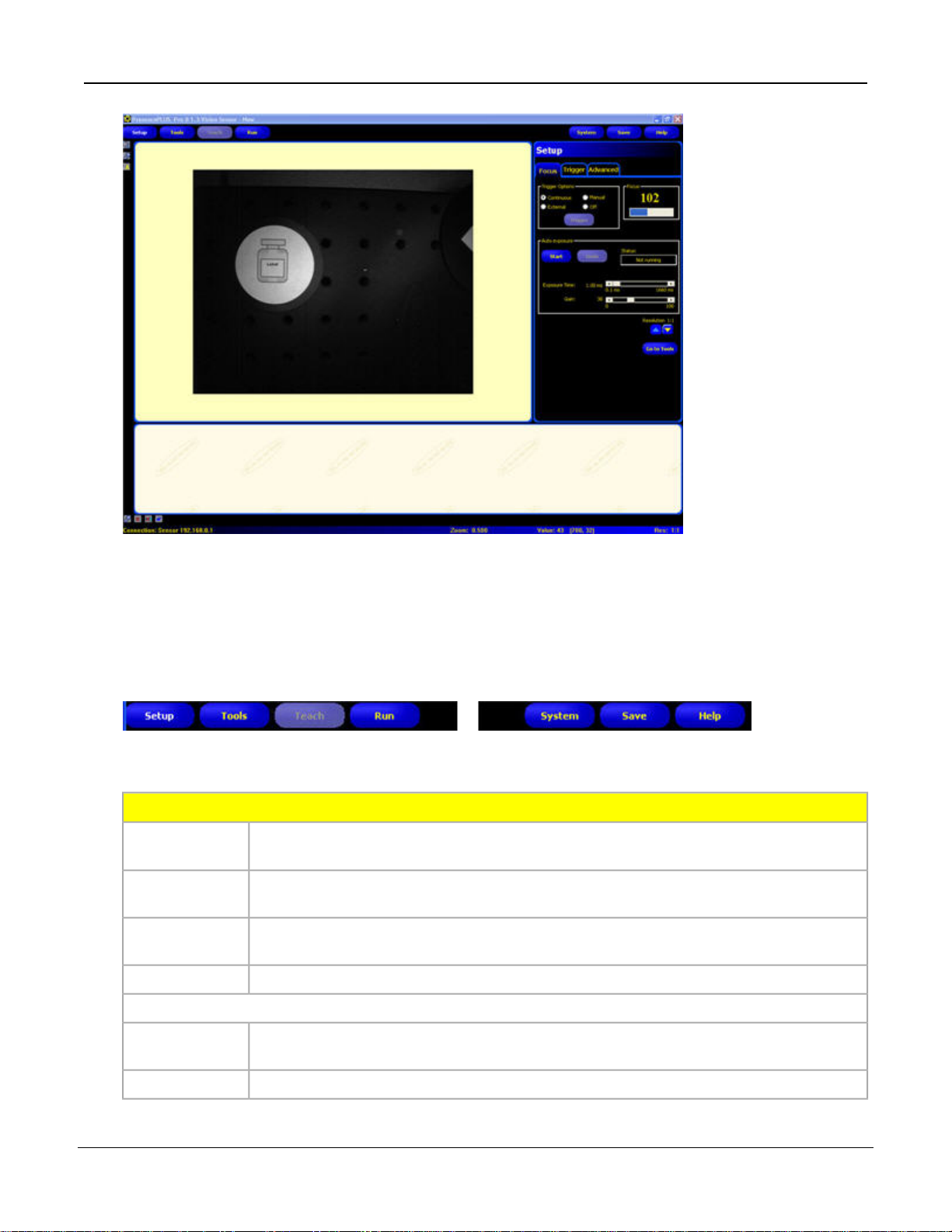
Setup
4.1 Setup Screen
The Vision sensor has two modes: running and idle. If the sensor is idle when you start up the PresencePLUS
software while your PC is connected, the software starts in the Setup screen. If the sensor is running, then the
software starts in the Run screen.
4.2 Capturing a Reference Image
The reference image is used as a template for developing an inspection. The Vision tools use this image to
acquire the critical information needed for the inspection.
Acquiring a quality image is crucial for a successful inspection. A quality image shows a measurable and
repeatable difference between good products (which pass inspection) and bad products (which fail inspection).
Most commonly, what determines the quality of the image is the illumination.
4
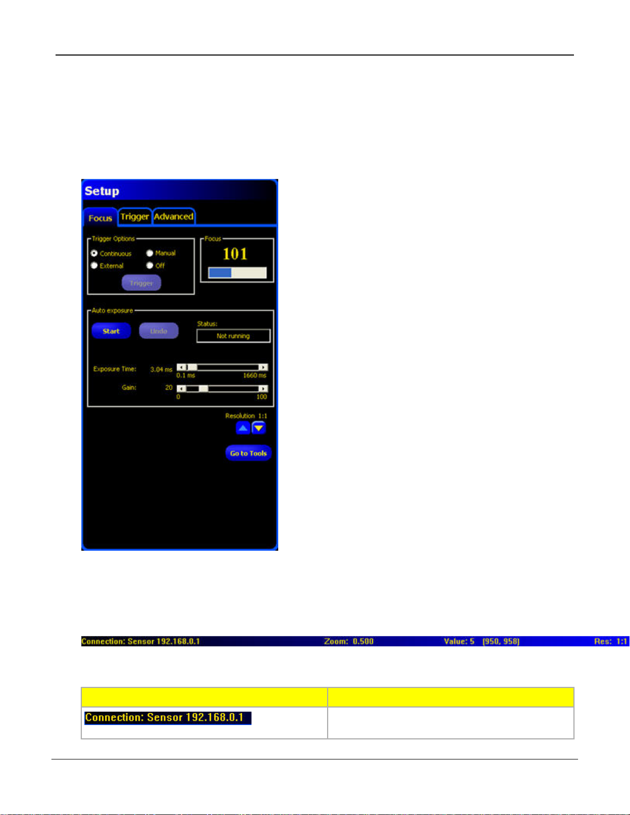
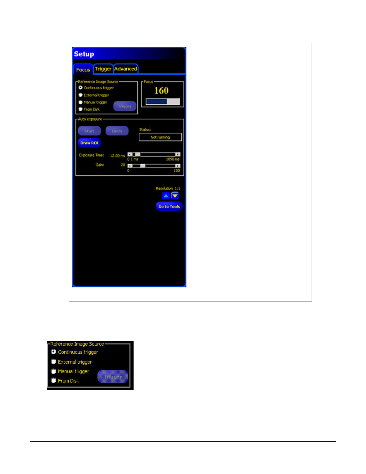
4.3 Focus Tab
The Focus tab on the Setup screen is used to:
•
Reference Image Source4.3.1 Reference Image Source on page 30
•
Focus Value4.3.2 Focus Value on page 31
•
Auto Exposure4.3.3 Auto Exposure on page 31
Focus tab
P/N 000000
Tel: 763.544.3164
29Banner Engineering Corp. - Minneapolis, MN USA - www.bannerengineering.com
7/2009Setup
4.3.1 Reference Image Source
Before capturing an image, you need to determine what will trigger the Sensor to capture and image.
The Sensor can be triggered to capture an image in one of the following ways.
30
Tel: 763.544.3164
P/N 000000Banner Engineering Corp. - Minneapolis, MN USA - www.bannerengineering.com
Loading...