


WLS27CWGRXX3 0570 HS24Q
Banner WLS27CWGRXX3 0570 HS24Q, WLS27XWGRXX3 1130 HS24Q, WLS27XGYRXX3 0570 DS24Q, WLS27CWGRYB5 1130 DS24Q, WLS27XWGRXX3 0570 HS24Q Quick Start Manual
...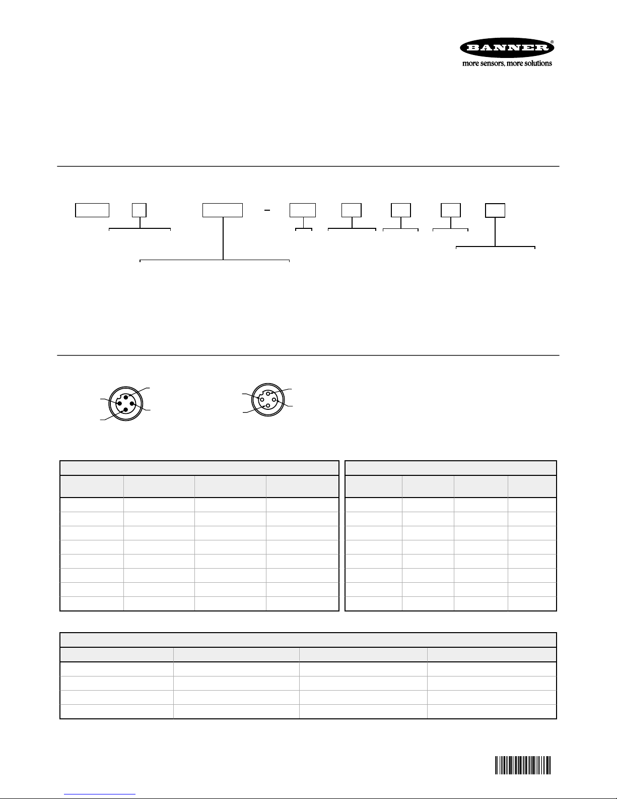
WLS27
ConnectorWindow
Lighted
Length (mm)
Colors 1-5 and ControlCascadableFamily
C = Cascadable
X = Non-cascadable
WGRXX3 = White, Green, Red with override control
WYRXX3 = White, Yellow, Red with override control
GYRXX3 = Green, Yellow, Red with override control
WGRYB5 = White, Green, Red, Yellow, Blue with binary control
WGRXX6 = White, Green, Red with I/O Block control
WYRXX6 = White, Yellow, Red with I/O Block control
GYRXX6 = Green, Yellow, Red with I/O Block control
0285
0570
0850
1130
D = Diffused
Q = Integral 4-pin M12 QD
(mating cordset required)
X
WGRXX3 0285 D
Q
Construction
S
S = Sealed
Voltage
24
24 = 24V dc
H = Heavy Diffused
1
4
3
2
2
3
4
1
WLS27 Multicolor LED Strip Light with EZ-
201895
STATUS
™
Quick Start Guide
This guide is designed to help you set up and install the WLS27 Multicolor LED Strip Light. For complete information on programming, performance,
troubleshooting, dimensions, and accessories, please refer to the Instruction Manual at
the Instruction Manual. Use of this document assumes familiarity with pertinent industry standards and practices.
Models
www.bannerengineering.com
. Search for p/n 201896 to view
Wiring Diagrams
Male
3 Color Override Control
Input 1: Pin 1
Brown Wire
— — — Light OFF
+24 V dc — — Color 1 ON
— +24 V dc — Color 2 ON
+24 V dc +24 V dc — Color 2 ON
— — +24 V dc Color 3 ON
+24 V dc — +24 V dc Color 3 ON
— +24 V dc +24 V dc Color 3 ON
+24 V dc +24 V dc +24 V dc Color 3 ON
3 Color I/O Block Control
Input 1: Pin 1 Brown Wire Input 2: Pin 4 Black Wire Input 3: Pin 2 White Wire LED Color
Original Document
201895 Rev. C
(Color 3 overrides Colors 1 and 2, Color 2 overrides Color 1)
Input 2: Pin 4 Black
Wire
(Input 1 is always ON through the block)
+24 V dc — — Light OFF
+24 V dc +24 V dc — Color 1 ON
+24 V dc — +24 V dc Color 2 ON
+24 V dc +24 V dc +24 V dc Color 3 ON
Input 3: Pin 2 White
Wire
Female
LED Color
18 June 2018
Key
Pin 1 Brown: Input 1
Pin 2 White: Input 3
Pin 3 Blue: DC Common
Pin 4 Black: Input 2
5 Color Binary Control
Input 1: Pin 1
Brown Wire
— — — Light OFF
+24 V dc — — Color 1 ON
— +24 V dc — Color 2 ON
— — +24 V dc Color 3 ON
+24 V dc +24 V dc — Color 4 ON
+24 V dc — +24 V dc Color 5 ON
— +24 V dc +24 V dc Light OFF
+24 V dc +24 V dc +24 V dc Light OFF
(Binary input state controls color)
Input 2: Pin 4
Black Wire
Input 3: Pin 2
White Wire
LED Color
 Loading...