


U-GAGE™ T30 Series with Analog and Discrete Outputs
Ultrasonic Sensors with TEACH-Mode Programming
U-GAGE T30 Series Features
•Fast, easy-to-use TEACH-mode programming; no potentiometer adjustments
•Program both outputs together or independently, with either an upward or a downward analog output slope
•Remote TEACH input for security and convenience
•Choose models with 150 mm to 1 m range (7.9" to 39.4") or 300 mm to 2 m range (11.8" to 78.7")
•Wide operating temperature range of -20° to +70°C (-13° to +158°F)
•Choose models with NPN or PNP discrete output, plus 0 to 10V dc or 4 to 20 mA sourcing analog output
•LED indicators for Power ON/OFF; Signal Strength; and Analog/Discrete Outputs Conducting
•Choose 2 m (6.5') or 9 m (30') integral unterminated cable or 5-pin Euro-style QD connector
•Compact, self-contained sensor package
•Rugged design for use in demanding sensing environments; rated IEC IP67, NEMA 6P
|
|
|
|
|
Ultrasonic, 228 or 128 kHz |
|
|
U-GAGE T30 Series Proximity Mode Models |
|
||
|
Range and |
|
Supply |
|
|
Models |
Frequency |
Cable* |
Voltage |
Discrete Output |
Analog Output Response Time |
T30UINA |
|
2 m (6.5') |
|
NPN (sinking) |
|
T30UINAQ |
|
5-pin Euro QD |
|
4 to 20 mA |
|
|
12 to 24V dc |
|
|||
T30UIPA |
150 mm to 1 m |
2 m (6.5') |
|
Sourcing |
|
|
PNP (sourcing) |
||||
T30UIPAQ |
(5.9" to 39") |
5-pin Euro QD |
|
|
|
|
|
48 milliseconds |
|||
T30UUNA |
|
2 m (6.5') |
|
|
|
228 kHz |
|
NPN (sinking) |
|
||
T30UUNAQ |
5-pin Euro QD |
|
0 to 10V dc |
||
15 to 24V dc |
|
||||
T30UUPA |
|
2 m (6.5') |
|
Sourcing |
|
|
|
PNP (sourcing) |
|||
T30UUPAQ |
|
5-pin Euro QD |
|
|
|
|
|
|
|
||
T30UINB |
|
2 m (6.5') |
|
NPN (sinking) |
|
T30UINBQ |
|
5-pin Euro QD |
|
4 to 20 mA |
|
|
12 to 24V dc |
|
|||
T30UIPB |
300 mm to 2 m |
2 m (6.5') |
|
Sourcing |
|
|
PNP (sourcing) |
||||
T30UIPBQ |
(11.8" to 79") |
5-pin Euro QD |
|
|
|
|
|
96 milliseconds |
|||
T30UUNB |
|
2 m (6.5') |
|
|
|
128 kHz |
|
NPN (sinking) |
|
||
T30UUNBQ |
5-pin Euro QD |
|
0 to 10V dc |
||
15 to 24V dc |
|
||||
T30UUPB |
|
2 m (6.5') |
|
Sourcing |
|
|
|
PNP (sourcing) |
|||
T30UUPBQ |
|
5-pin Euro QD |
|
|
|
|
|
|
|
||
*NOTES:
•9 m (30') cables are available by adding suffix “W/30” to the model number of any cabled sensor (e.g., T30UINA/30).
•A model with a QD connector requires an optional mating cable, see page 9.
Printed in USA |
01/03 |
P/N 57438 Rev. C |

U-GAGE™ T30 Series with Analog and Discrete Outputs
U-GAGE T30 Series Overview
The U-GAGE is an easy-to-use ultrasonic sensor, ideal for demanding environments. Simple push-button programming provides flexibility for a variety of applications. Excellent for measurement applications such as sensing of liquid levels in a tank or, for example, determining box heights for sorting purposes.
Each sensor includes both an analog and a discrete output, which may be programmed independently with different window limits or together with identical limits. Each output has the option of being set with a sensing distance set point centered within a 10-mm window.
U-GAGE T30 Series Programming
Window Limits
Window limits may be taught to the sensor in several ways. The following methods describe the programming procedures using the push buttons on the back of the sensor; remote programming (remote TEACH) procedures are described on page 4.
NOTE: When the sensor changes state between PROGRAM and RUN modes, all of the LED indicators turn OFF momentarily, before the appropriate LEDs come ON as described below. The sensing window limits expand temporarily to full scale (max range) during PROGRAM mode.
Teaching Limits for Either Analog or Discrete Output
1.Choose the output for the first set of window limits (analog or discrete) and push and hold the corresponding button until the green Power LED goes OFF and the appropriate yellow Output LED turns ON (solid). This indicates the sensor is waiting for the first limit.
2.Position the target for the first limit and briefly “click” the same button. This will teach the sensor the first limit. The yellow Output LED will flash to acknowledge receiving the first window limit; it is now waiting for the second limit.
3.Position the target for the second limit and “click” the button again. This will teach the sensor the second limit. The yellow Output LED turns OFF and the green Power LED comes ON; the sensor is now in normal RUN mode.
4.Repeat for the other output (analog or discrete) if a second output is desired.
NOTE: Press and hold the same button > 2 seconds (before teaching the second limit) to exit PROGRAM mode without saving any changes. The sensor will revert to the last saved program.
Teaching Analog or Discrete Limits Using the Auto-Zero Feature
For some applications, a sensing distance set point centered within a minimum sensing window may be required. The TEACH procedure for this application is simple: teaching the same limit twice causes the sensor to program a 10-mm window centered on the position taught (position ±5 mm).
NOTE: The sensor allows for some forgiveness in this procedure. If the two limits are not exactly the same (but closer than the minimum 10-mm window required), the sensor will put the set point at the “average” of the two limits.
Banner Engineering Corp. • Minneapolis, MN U.S.A.
2 www.bannerengineering.com • Tel: 763.544.3164 P/N 57438 Rev. C
U-GAGE™ T30 Series with Analog and Discrete Outputs
Teaching Identical Limits for Both Analog and Discrete Outputs Simultaneously
To set both the analog and the discrete outputs at exactly the same limits, both may be set simultaneously.
1.Push and hold either the Analog or the Discrete programming push button until the yellow Output LED turns ON. Push and hold the other push button until its yellow Output LED turns ON. The sensor is waiting for the first limit.
2.Position the target for the first limit and “click” either programming push button. Both yellow LEDs will flash to acknowledge receiving the first window limit; the sensor is now waiting for the second limit.
3.Position the target for the second limit and “click” either button again to teach the sensor the second limit.
4.The green Power LED will come ON to indicate that the sensor will now function in normal RUN mode; both yellow Output LEDs will remain ON if the outputs are conducting within the window limits.
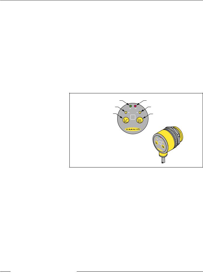
Green Power ON/OFF LED |
|
|
Red Signal Strength LED |
|||||||
Yellow Analog Output LED |
POWER |
SIGNAL |
Yellow Discrete Output LED |
|||||||
Analog Output |
|
OUTPUT |
Discrete (Switched) Output |
|||||||
ANALOG |
DISCRETE |
|||||||||
Programming Push Button |
Programming Push Button |
|||||||||
|
|
|||||||||
|
U-GAGE™ |
|
|
|
|
|
|
|
||
|
|
|
PO |
|
|
|
|
|||
|
|
|
|
|
WER |
|
|
|
||
|
|
|
A |
|
|
OU |
SI |
|
||
|
|
|
N |
|
|
G |
||||
|
|
|
|
AL |
TP |
|
NA |
|||
|
|
|
|
|
OG |
|
UT |
|
L |
|
|
|
|
|
|
|
|
DI |
|
||
|
|
|
|
|
|
|
|
SC |
||
|
|
|
|
|
|
|
|
|
RE |
|
|
|
|
|
|
U- |
|
|
TE |
||
|
|
|
|
|
|
|
|
|||
|
|
|
|
|
|
G |
|
|
|
|
|
|
|
|
|
|
A |
|
|
||
|
|
|
|
|
|
|
G |
|
||
|
|
|
|
|
|
|
E |
|||
|
|
|
|
|
|
|
|
|
™ |
|
Figure 1. U-GAGE T30 Series sensor programming push buttons and indicators
General Notes on Programming:
1.The sensor will return to RUN mode if the first TEACH condition is not registered within 120 seconds.
2.After the first limit is taught, the sensor will remain in PROGRAM mode until the TEACH sequence is finished.
3.Press and hold the programming push button > 2 seconds (before teaching the second limit) to exit PROGRAM mode without saving any changes. The sensor will revert to the last saved program.
Banner Engineering Corp. • Minneapolis, MN U.S.A.
www.bannerengineering.com • Tel: 763.544.3164 3 P/N 57438 Rev. C

U-GAGE™ T30 Series with Analog and Discrete Outputs
Remote Programming
To program the sensor remotely or to disable the keypad, the Remote Programming function may be used. Disabling the keypad prevents anyone on the production floor from adjusting any of the programming settings. Connect the gray wire of the sensor to +12 to 24V dc, with a remote programming switch connected between them. NOTE: The impedance of the remote teach input is 55 kΩ.
Programming is accomplished by following the sequence of input pulses. The duration of each pulse (corresponding to a push button “click”), and the period between multiple pulses, are defined as: 0.04 seconds < T < 0.8 seconds.
• |
1 pulse: |
Programs first discrete limit. Wait > 0.8 sec. Next pulse programs |
|
|
second discrete limit. |
• |
2 pulses: |
Programs first analog limit. Wait > 0.8 sec. Next pulse programs |
|
|
second analog limit. |
• |
3 pulses: |
Programs first analog and discrete limit. Wait > 0.8 sec. Next pulse |
|
|
programs second analog and discrete limit. |
• |
4 pulses: |
Disables (locks out) or enables the keypad for security. |
|
T |
|
> 0.8 sec |
|
T |
|
Discrete |
|
|
|
|
|
|
Limits Only |
|
|
|
|
Teach Second |
|
Teach First |
|
|
|
|
||
Discrete Limit |
|
|
|
Discrete Limit |
|
|
|
T |
T |
T |
> 0.8 sec |
T |
|
Analog |
|
|
|
|
|
|
Limits Only |
|
|
Teach First |
|
Teach Second |
|
|
|
|
|
|
||
|
|
Analog Limit |
|
Analog Limit |
|
|
T |
T |
T |
T |
T |
> 0.8 sec |
T |
Analog & Discrete
Together
|
|
|
|
Teach First Limits |
|
Teach Second Limits |
T |
T |
T |
T |
T |
T |
T |
Push Button
Lockout
Push Button Lockout
0.04 sec < T < 0.8 sec
Figure 2. Timing programs for remote TEACH programming
NOTE: Hold the Remote line high > 2 seconds (before teaching the second limit) to exit PROGRAM mode without saving any changes. The sensor will revert to the last saved program.
Banner Engineering Corp. • Minneapolis, MN U.S.A.
4 www.bannerengineering.com • Tel: 763.544.3164 P/N 57438 Rev. C
 Loading...