


 Loading...
Banner M18TIP8Q, M18TUP8Q, M18TUP8, M18TUP6EQ, M18TUP14 User Manual
...T-GAGE™ M18T Series Infrared Temperature Sensors
18 mm sensor with 0-10V and 4-20mA analog output and TEACH-mode programming
For the latest technical information about this product, including specifications, dimensions, and wiring, see www.BannerEngineering.com
Features
• Fast 75 ms response time
• Easy-to-use TEACH mode programming; no potentiometer adjustments
• Small self-contained package, no auxiliary controller needed
• Rugged encapsulated design for harsh environments
• Choose 2 meter or 9 meter unterminated cable, or 5-pin Euro-style QD connector
• Product motion not required for sensing
• Remote Teach available in both Static and Dynamic modes
• Alarm output for signal maximum
• Programming for either positive or negative analog slope based on teach order
Models
Model |
Cable* |
D:S Ratio |
Sensing Face |
Supply Voltage |
Output |
|
|
|
|
|
|
M18TUP8 |
5-wire, 2 m (6.5') shielded cable |
8:1 |
Integrated lens |
|
|
|
|
|
|
||
M18TUP8Q |
5-pin Euro-style integral QD |
|
|
||
|
|
|
|
||
|
|
|
|
|
0 to 10V dc ana- |
M18TUP6E |
5-wire, 2 m (6.5') shielded cable |
|
Enclosed Plastic face |
|
|
|
|
6:1 |
(for food industry use) |
|
log, plus PNP |
M18TUP6EQ |
5-pin, Euro-style integral QD |
|
|||
|
|
|
Alarm |
||
M18TUP14 |
5-wire, 2 m (6.5') shielded cable |
14:1 |
Germanium lens |
|
|
|
|
|
|
|
|
M18TUP14Q |
5-pin, Euro-style integral QD |
|
12 to 30V dc |
|
|
|
|
|
|||
|
|
|
|
|
|
M18TIP8 |
5-wire, 2 m (6.5') shielded cable |
8:1 |
Integrated lens |
|
|
|
|
||||
|
|
|
|
|
|
M18TIP8Q |
5-pin Euro-style integral QD |
|
|
|
|
|
|
|
|
||
|
|
|
|
|
4 - 20 mA ana- |
M18TIP6E |
5-wire, 2 m (6.5') shielded cable |
|
Enclosed Plastic face |
|
|
|
|
6:1 |
(for food industry use) |
|
log, plus PNP |
M18TIP6EQ |
5-pin, Euro-style integral QD |
|
|||
|
|
|
Alarm |
||
M18TIP14 |
5-wire, 2 m (6.5') shielded cable |
14:1 |
Germanium lens |
|
|
|
|
|
|
|
|
M18TIP14Q |
5-pin, Euro-style integral QD |
|
|
|
|
|
|
|
|
||
|
|
|
|
|
|
* For 9 m (30') cable, add suffix "W/30" to the model number of any cabled model (e.g., M18TUP8 W/30). A model with a QD connector requires an accessory mating cable. See Quick-Disconnect Cables on page 8 for more information.
WARNING: Not To Be Used for Personnel Protection
Never use this product as a sensing device for personnel protection. Doing so could lead to serious injury or death. This product does NOT include the self-checking redundant circuitry necessary to allow its use in personnel safety applications. A sensor failure or malfunction can cause either an energized or de-energized sensor output condition.
P/N 123698_web |
5/14/2012 |
Rev. A |
|

T-GAGE™ M18T Series Infrared Temperature Sensors
Overview
The T-GAGE analog sensor is a passive, non-contacting, temperature-based device. It is used to detect object(s) temperature within a sensing window and output a proportional voltage or current.
While it looks and operates just like an Expert™ photoelectric sensor, the T- GAGE detects the infrared light energy emitted by objects, instead of its own emitted light. The sensor uses a thermopile detector, made up of multiple infra- red-sensitive elements (thermocouples) to detect this infrared energy within its field of view (see Figure 2. Detection spot size versus distance from sensor on page 2).
Potential applications include:
•Hot part detection (baked goods, metals, bottles, rubber)
•Ejection verification of injection-molded parts
•Flame process verification
•Hot glue detection (packaging equipment, book binding, product assembly)
•Cold part detection (frozen foods, ice, dairy)
•Roller monitoring
NOTE: The T-GAGE M18T sensor is not intended for absolute temperature measurement or for safety-re- lated fire detection use.
|
Figure 1. Sensor Features |
|
|
1 |
Power/Teach LED |
|
|
2 |
Alarm Output LED |
|
|
3 |
TEACH Push Button |
|
|
Sensing Field of View
The sensing range is determined by the sensor’s field of view (FOV), or viewing angle, combined with the size of the object(s) being detected (see Figure 2. Detection spot size versus distance from sensor on page 2). The sensor’s distance-to- spot size ratio (D:S ratio) is inversely related to the viewing angle; a sensor with a small viewing angle will have a large D:S ratio. The T-GAGE M18T sensors have D:S ratios of 6:1, 8:1 or 14:1. For a sensor with an 8:1 D:S ratio, the sensor’s spot size is a 1" diameter circle at a distance of 8"; farther from the sensor face the spot size will be larger.
Spot Size (see table)
Distance (mm) |
|
|
|
|
200 |
400 |
600 |
800 |
1000 |
Sensor D:S |
|
|
|
|
Distance from Sensor Face Versus Spot Size |
|
|
|||||
Ratio |
|
|
|
|
|
|
|
|
|
|
|
|
100 |
200 |
300 |
400 |
|
500 |
600 |
700 |
800 |
900 |
1000 |
Distance (mm) |
|
|
|
|||||||||||
|
|
|
|
|
|
|
|
|
|
|
|
|
6:1 |
17 |
33 |
50 |
67 |
|
83 |
100 |
117 |
133 |
150 |
167 |
|
|
|
|
|
|
|
|
|
|
|
|
|
|
8:1 |
13 |
25 |
38 |
50 |
|
63 |
75 |
88 |
100 |
113 |
125 |
Spot Size (mm) |
|
|
|
|
|
|
|
|
|
|
|
|
|
14:1 |
7 |
14 |
21 |
29 |
|
36 |
43 |
50 |
57 |
64 |
71 |
|
|
|
|
|
|
|
|
|
|
|
|
|
|
Figure 2. Detection spot size versus distance from sensor
2 |
www.bannerengineering.com - tel: 763-544-3164 |
P/N 123698_web |
|
|
Rev. A |
T-GAGE™ M18T Series Infrared Temperature Sensors
Apparent Temperature
Two factors that have a large influence on apparent temperature are the object’s emissivity and whether or not the object fills the sensor’s field of view.
Object Emissivity:
A “blackbody” is a “perfect” emitter, with an emissivity of 1.0 at all temperatures and wavelengths. Most surfaces emit only a fraction of the amount of thermal energy that a blackbody would. Typical T-GAGE applications will be sensing objects with emissivities ranging from 0.5 to 0.95. Many references are available with tables of emissivity coefficients for common materials. In general, shiny unpainted metals have low emissivity, while non-glossy surfaces have high emissivity.
Shiny surfaces: a mirror or shiny surface can redirect an object’s emitted energy to an undesired location, or even bring additional unintended thermal energy into the sensor’s field of view (see Application Note on page 6).
Object Size:
If the object being detected does not fill the sensor’s field of view, then the sensor will average the temperature of that object and whatever else is in the sensing field of view. For the sensor to collect the maximum amount of energy, the object should completely fill the sensor’s field of view. However, in some applications, when the object is too small, this may not be possible. In such cases, if the object is hot enough, the thermal contrast may still be adequate to trigger the sensor’s output.
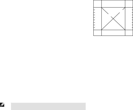
Alarm Output
The alarm output will activate when the analog output is at 10V or 20mA, depending on model (see Figure 3. Analog/Alarm outputs as a function of taught conditions on page 3).
Analog Output
The T-GAGE analog sensor can be programmed for either positive or negative output slope, based on the teach order (see Figure 3. Analog/ Alarm outputs as a function of taught conditions on page 3). If the cold limit is taught first, the slope will be positive; if the hot limit is taught first, the slope will be negative. Banner’s scalable output automatically distributes the output signal over the width of the programmed sensing window.
|
Alarm |
Alarm |
|
Second |
|
Output |
Output |
|
Taught |
10 |
ON |
ON |
20 |
Condition |
|
|
|||
Analog Output (V dc) |
|
Positive Slope |
Analog Output (mA) |
|
Negative Slope |
|
|
||
|
|
|
||
0 |
|
|
4 |
First |
|
|
|
|
Taught |
|
Cold |
Hot |
|
Condition |
|
|
|
||
|
Condition |
Condition |
|
|
Positive Slope: Cold condition taught first
Negative Slope: Hot condition taught first
Figure 3. Analog/Alarm outputs as a function of taught conditions
Sensor Programming
Two TEACH methods may be used to program the sensor:
•Teach individual minimum and maximum limits (Two-Point Static Teach), or
•Dynamic Teach for on-the-fly programming.
The sensor may be programmed either via its push button, or via a remote switch. Remote programming also may be used to disable the push button, preventing unauthorized personnel from adjusting the programming settings. To access this feature, connect a normally open switch between the sensor’s gray wire and dc common or connect the gray wire to a digital input (PLC).
NOTE: The impedance of the Remote Teach input is 3 kΩ.
Programming is accomplished by following the sequence of input pulses (see Teaching Limits Using Two-Point Static TEACH on page 4). The duration of each pulse (corresponding to a push button “click”), and the period between multiple pulses, are defined as “T”:
0.04 seconds < T < 0.8 seconds
P/N 123698_web |
www.bannerengineering.com - tel: 763-544-3164 |
3 |
Rev. A |
|
|
Loading...