


EZ-SCREEN

EZ-SCREEN™Grid
Instruction Manual
Printed in USA
09/01 P/N 68410
9714 10th Avenue North • Minneapolis, MN 55441
Phone: 763.544.3164 • http://www.bannerengineering.com
Email: sensors@bannerengineering.com
Section Contents
Section 1 Introduction Overview . . . . . . . . . . . . . . . . . .Page 4
Section 2 System Components and Specifications . . . .Page 10
Section 3 Installation and Alignment . . . . . . . . . . . . . .Page 16
Section 4 System Operation . . . . . . . . . . . . . . . . . . . .Page 40
Section 5 Troubleshooting and Maintenance . . . . . . . .Page 45
Section 6 Periodic Checkout Procedures . . . . . . . . . . .Page 51
EZ-SCREEN Features
• Non-contact safety device for perimeter and
access guarding from dangerous machinery
• Diverse-redundant and self-checking design to
achieve control reliability and meet IEC 61496-1
type 4 requirements
•Choose models with 2, 3, or 4 beams, beam
spacing from 300 to 584 mm (12" to 23")
• Self-contained two-part system is optically
synchronized:
Needs no external controller
Needs no extra synchronization wire
Easy and economical to install
• Operating range 0.8 to 20 m or 15 to 70 m
(2.6' to 65' or 49' to 230')
• Selectable external device monitoring
• Selectable trip or latch output
• Fast 24 millisecond output response time for all
models
• Easy-to-use removable terminal blocks or quickdisconnect options speed and simplify wiring
• Compact, robust housing
•Multiple mounting options
• Optional accessory interface module available
for ac or larger dc loads
• Configuration settings accessible from the front,
with supplied tool. Sensor settings can be
changed while sensor remains mounted.
US
LISTED

page 2
Banner Engineering Corp. • Minneapolis, MN U.S.A.
www.bannerengineering.com • Tel: 763.544.3164
EZ-SCREEN Grid
Instruction Manual
Important ... read this page before proceeding!
In the United States, the functions that Banner EZ-SCREEN™Systems are intended to perform are
regulated by the Occupational Safety and Health Administration (OSHA). However, whether or not
any particular EZ-SCREEN System installation meets all applicable OSHA requirements depends
upon factors that are beyond the control of Banner Engineering Corp. These factors include the
details of how the EZ-SCREEN System is applied, installed, wired, operated, and maintained.
Banner Engineering Corp. has attempted to provide complete application, installation, operation,
and maintenance instructions. In addition, we suggest that any questions regarding application or
use of EZ-SCREEN Systems be directed to the factory applications department at the telephone
number or addresses shown at the bottom of this page.
Banner EZ-SCREEN Systems can guard against accidents only when they are properly installed
and integrated into the machine, properly operated, and properly maintained. See Section 3 of this
manual for installation procedures, considerations, and precautions. See Sections 4 and 5 for
operating and maintenance information. It is the responsibility of the purchaser and/or user to
apply this EZ-SCREEN System in full compliance with OSHA regulations.
In addition to OSHA regulations, several other organizations provide informational material on the
use of machine guard devices. The user is referred to the American National Standards Institute
(ANSI), the Robotics Industries Association (RIA), the Association for Manufacturing Technology
(AMT), and others. Banner Engineering Corp. makes no claim regarding a specific recommendation of any organization, the accuracy or effectiveness of any information provided, or the
appropriateness of the provided information for a specific application.
The user has the responsibility to ensure that all local, state, and national laws, rules, codes, and
regulations relating to the use of this machine guarding system in any particular application are
satisfied. Extreme care is urged to ensure that all legal requirements have been met and that all
installation and maintenance instructions contained in this manual are followed.
Caution!!
Banner EZ-SCREEN Systems are for use only on machinery that can be stopped immediately after
a stop signal is issued. They may be used with part-revolution clutched machines that have the
ability to stop at any point in their stroke. Under no circumstances may the EZ-SCREEN System
be used on full-revolution clutched machinery. Banner EZ-SCREEN Systems may not be used as
tripping devices to initiate machine motion (PSDI applications) on mechanical power presses, per
OSHA regulation 29 CFR 1910.217.
Appropriate Applications
The Banner EZ-SCREEN Grid System
may be used in access-guarding and
perimeter-guarding applications only
with machinery that can be stopped
immediately after a stop signal is issued.
It may be used with part-revolution
clutched machines that have the ability
to stop at any point in their stroke.
Under no circumstances may the EZSCREEN Grid System be used to guard
full-revolution clutched machinery. The
Banner EZ-SCREEN Grid Systems may
not be used as tripping devices to
initiate machine motion (PSDI
applications) on mechanical power
presses, per OSHA regulation 29 CFR
1910.217.
The Banner EZ-SCREEN Grid System is
typically used in access-guarding or
perimeter-guarding applications for the
following types of machines:
• Assembly stations
• Manufacturing cells
• Automated production equipment
• Robotic work cells
The Banner EZ-SCREEN Grid System
may not be used in the following types
of applications:
• For hand or finger detection in pointof-operation guarding (see Section
3.1)
• In non-vertical area-guarding
applications
•To guard any machine that cannot be
stopped immediately after a stop
signal is issued, such as single-stroke
(or “full-revolution”) clutched
machinery
•To guard any machine with inadequate
or inconsistent machine response
time and stopping performance
•To guard any machine that ejects
materials or component parts through
the light grid
• In any environment that is likely to
adversely affect photoelectric sensing
system efficiency. For example,
corrosive chemicals or fluids or
unusually severe levels of smoke or
dust, if not controlled, may degrade
the efficiency of the safety light grid
Banner Engineering Corp.
9714 - 10th Avenue No.
Minneapolis, MN 55441
Email: sensors@bannerengineering.com
U.S. Standards Applicable to Use of EZ-SCREEN™ Systems
ANSI B11 Standards Safeguarding of Machine Tools
ANSI/RIA R15.06 Safety Requirements for Robot Systems
NFPA 79 Electrical Standard for Industrial Machinery
See pages 62 and 63 for information on these and other applicable standards,
and where to acquire copies.

page 3
Banner Engineering Corp. • Minneapolis, U.S.A.
www.bannerengineering.com • Tel: 763.544.3164
Table of Contents
EZ-SCREEN Grid
Instruction Manual
Table of Contents
1. Introduction — Overview . . . . . . . . . . . . . . . . . . . . . page 4
1.1 System Description . . . . . . . . . . . . . . . . . . . . . . . . . . . . . . 4
1.2 Applications and Limitations . . . . . . . . . . . . . . . . . . . . . . . 6
1.3 Control reliability . . . . . . . . . . . . . . . . . . . . . . . . . . . . . . . . 8
1.4 Operating features . . . . . . . . . . . . . . . . . . . . . . . . . . . . . . 8
2. System Components and Specifications . . . . . . . . . . . Page 10
2.1 Models Available . . . . . . . . . . . . . . . . . . . . . . . . . . . . . . . 10
2.2 Accessories . . . . . . . . . . . . . . . . . . . . . . . . . . . . . . . . . . . 10
2.3 Replacement parts . . . . . . . . . . . . . . . . . . . . . . . . . . . . . 12
2.4 Literature . . . . . . . . . . . . . . . . . . . . . . . . . . . . . . . . . . . . . 12
2.5 Specifications . . . . . . . . . . . . . . . . . . . . . . . . . . . . . . . . . 13
2.6 Dimensions . . . . . . . . . . . . . . . . . . . . . . . . . . . . . . . . . . . 15
3. Installation and Alignment . . . . . . . . . . . . . . . . . . . Page 16
3.1 Appropriate applications . . . . . . . . . . . . . . . . . . . . . . . . . 16
3.2 Security Protocol . . . . . . . . . . . . . . . . . . . . . . . . . . . . . . 17
3.3 Mechanical Installation Considerations . . . . . . . . . . . . . . 18
3.3.1 Minimum Separation Distance (Ds) . . . . . . . . . . . . . . 18
3.3.2 Supplemental Safeguarding . . . . . . . . . . . . . . . . . . . . 21
3.3.3 Emitter/Receiver Orientation . . . . . . . . . . . . . . . . . . . 22
3.3.4 Adjacent Reflective Surfaces . . . . . . . . . . . . . . . . . . . 23
3.3.5 Use of Corner Mirrors . . . . . . . . . . . . . . . . . . . . . . . . 24
3.3.6 Avoiding Electrical and Optical Noise . . . . . . . . . . . . . 25
3.3.7 Multiple-System Applications . . . . . . . . . . . . . . . . . . 25
3.4 Mechanical Mounting Procedure . . . . . . . . . . . . . . . . . . . 26
3.5 Electrical Connections . . . . . . . . . . . . . . . . . . . . . . . . . . . 28
3.6 Light Grid Initial Checkout and
Optical Alignment Procedure . . . . . . . . . . . . . . . . . . . . . . 30
3.7 Electrical Interface to the Guarded Machine
(Permanent Hookup) . . . . . . . . . . . . . . . . . . . . . . . . . . . . 33
3.7.1 OSSD Output Connections . . . . . . . . . . . . . . . . . . . . . 33
3.7.2 FSD Interfacing Connections . . . . . . . . . . . . . . . . . . . 33
3.7.3 Machine Primary Control Elements and
EDM Inputs . . . . . . . . . . . . . . . . . . . . . . . . . . . . . . . 35
3.7.4 Remote Test Input . . . . . . . . . . . . . . . . . . . . . . . . . . . 36
3.8 Preparing for System Operation . . . . . . . . . . . . . . . . . . . . 36
4. System Operation . . . . . . . . . . . . . . . . . . . . . . . . . Page 40
4.1 System Configuration Settings . . . . . . . . . . . . . . . . . . . . . 40
4.2 Reset Procedures . . . . . . . . . . . . . . . . . . . . . . . . . . . . . . . 41
4.2.1 Receiver Resets . . . . . . . . . . . . . . . . . . . . . . . . . . . . 41
4.2.2 Emitter Resets . . . . . . . . . . . . . . . . . . . . . . . . . . . . . 41
4.3 Status Indicators . . . . . . . . . . . . . . . . . . . . . . . . . . . . . . . 41
4.4 Normal Operation . . . . . . . . . . . . . . . . . . . . . . . . . . . . . . . 43
4.5 Periodic Checkout Requirements . . . . . . . . . . . . . . . . . . . 44
5. Troubleshooting and Maintenance . . . . . . . . . . . . . . Page 45
5.1 Troubleshooting Lockout Conditions . . . . . . . . . . . . . . . . . 45
5.1.1 Receiver Error Codes . . . . . . . . . . . . . . . . . . . . . . . . . 46
5.1.2 Emitter Error Codes . . . . . . . . . . . . . . . . . . . . . . . . . . 48
5.2 Electrical and Optical Noise . . . . . . . . . . . . . . . . . . . . . . . 49
5.3 Test Mode . . . . . . . . . . . . . . . . . . . . . . . . . . . . . . . . . . . . 50
5.4 Servicing and Maintenance . . . . . . . . . . . . . . . . . . . . . . . 50
6. Checkout Procedures . . . . . . . . . . . . . . . . . . . . . . . Page 51
6.1 Schedule of Checkouts . . . . . . . . . . . . . . . . . . . . . . . . . . . 51
6.2 Trip Test . . . . . . . . . . . . . . . . . . . . . . . . . . . . . . . . . . . . . 51
6.3 Commissioning Checkout . . . . . . . . . . . . . . . . . . . . . . . . . 53
6.4 Daily Checkout . . . . . . . . . . . . . . . . . . . . . . . . . . . . . . . . . 55
6.5 Semi-Annual Checkout . . . . . . . . . . . . . . . . . . . . . . . . . . . 56
Appendix –
QD Models . . . . . . . . . . . . . . . . . . . . . . . . . . . . . .Page 57
QD Model Accessories . . . . . . . . . . . . . . . . . . . . . .Page 58
Accessory Bracket Dimensions . . . . . . . . . . . . . . . . . Page 59
Glossary of Safety Terms . . . . . . . . . . . . . . . . . . . . . . . Page 60
Safety Standards . . . . . . . . . . . . . . . . . . . . . . . . . . . . Page 62

page 4
Banner Engineering Corp. • Minneapolis, MN U.S.A.
www.bannerengineering.com • Tel: 763.544.3164
System Introduction
EZ-SCREEN Grid
Instruction Manual
1. Introduction — Overview
1.1 System Description
The Banner EZ-SCREEN™ Grid System is an optically synchronized,
microprocessor-controlled, opposed-mode optoelectronic “light grid.” This
economical two-part system consists of an emitter and receiver. The system
requires no external controller or sync wire between the emitter and receiver; the
microprocessors are located within the receiver. The receiver has two solid-state
safety outputs to control 24V dc loads. If an ac-powered MPCE or other load is
required, an accessory interface module may be used to convert the EZ-SCREEN
dc outputs to isolated, forced-guided relay contacts. (See Section 2.2 and Figures
3-17 and 3-18 for more information.)
Figure 1-1. EZ-SCREEN Models
SG..2-500
2 beams
500 mm (19.7")
Spacing
SG..3-400
3 beams
400 mm (15.7") Spacing
SG..3-533
3 beams
533 mm (21") Spacing
SG..4-300
4 beams
300 mm (11.8") Spacing
SG..2-584
2 beams
584 mm (23") Spacing
Each EZ-SCREEN Grid System
needs only an emitter and a receiver.
Optional Interface Module is available for
switching ac or larger dc loads. (See
Section 2.2 for more information on the
Interface Module.)
See pages 57-58 for quick-disconnect options.
Dots on
housing
indicate beam
placement
(dot size is
exaggerated
for visibility).

page 5
Banner Engineering Corp. • Minneapolis, MN U.S.A.
www.bannerengineering.com • Tel: 763.544.3164
System Introduction
EZ-SCREEN Grid
Instruction Manual
Five sensor configurations are available, with two, three or four beams; emitters
have short-range and long-range versions. (Receivers are the same for both
long-range and short-range operation.) Beam spacing ranges from 300 mm to
584 mm (12" to 23"), depending on the model. The configuration (the overall
length and beam spacing) required for an application is determined by the
application and the safety standards being followed. Models SG..E/R2-584 and
SG..E/R3-533 are based on recommendations in ANSI/RIA R15.06 and ANSI B11
standards. Models SG..E/R4-300, SG..E/R3-400, and SG..E/R2-500 are based on
recommendations in EN 999. See pages 60 and 61 for a list of applicable safety
standards. Emitters and receivers do not need matching serial numbers to work
together; any emitter may be used with any receiver of the same length and beam
configuration. Figure 1-1 shows the sizes and beam configurations of the models
available.
The emitter/receiver beams feature a narrow effective aperture angle (EAA) for
effective long-range sensing — up to 70 meters, depending on model. The EAA
satisfies IEC 61496-2 (type 4), including requirements for extraneous reflections
and misalignment.
Cabling is accomplished in one of two ways. User-supplied cable may be hardwired into the emitter and receiver housings, using the removable terminals in
the end cap of each sensor, or Mini-style quick-disconnect models are available
for easier installation; see pages 57-58. See Section 2.5 for cable specifications
and Section 3.7 for wiring instructions.
Banner EZ-SCREEN Grid components may be purchased individually or in kits.
Kits include one emitter, one receiver, a keyed reset switch, and standard
mounting hardware for both sensors. When purchased separately, the emitter
and receiver each include one cable gland, mounting hardware for one sensor,
plus the accessory spanner wrench. The Key Reset switch also is available
separately, or the user may provide other means to reset the system (see
specifications in Section 2.5 for switch requirements).
The OSSD (solid-state safety outputs) are capable of performing a “handshake”
communication with the Muteable Safety Stop Interface (MSSI) or Universal
Safety Stop Interface (USSI) that are found on other Banner Engineering safety
products. The handshake protocol is satisfied by any Banner Engineering Safety
Category 4 (per ISO 13849-1/EN954-1) device with OSSD outputs or MSSI/USSI
inputs.
To ensure a Safety Category 4 (per ISO 13849-1/EN954-1) interface between the
two devices, the MSSI/USSI provides a “handshake request” that Banner
Engineering safety devices with OSSD solid-state outputs are capable of
responding to. This handshake verifies that the interface between the two devices
is capable of detecting certain unsafe failures that may occur, such as a shortcircuit to a secondary source of power or to the other channel, high input
resistance or loss of signal ground.

page 6
Banner Engineering Corp. • Minneapolis, MN U.S.A.
www.bannerengineering.com • Tel: 763.544.3164
System Introduction
EZ-SCREEN Grid
Instruction Manual
1.2 Applications and Limitations
The Banner EZ-SCREEN Grid System is designed for use in access-guarding and
perimeter-guarding applications. It is designed to be mounted vertically, in order
to detect a body or torso (rather than a hand or an arm) as a person enters a
hazardous area. It is not intended nor designed for hand or finger detection in
point-of-operation guarding or for area-guarding applications.
In perimeter-guarding and access-guarding applications, the light grid is vertical
or nearly vertical. In these applications, personnel typically can pass through the
light grid (which removes or stops the hazard), then may continue into the
hazardous area.
A recommended set of beam placement positions has become accepted in the
United States and Europe. The standards (ANSI/RIA R15.06, ANSI B11 and
EN 999) recommend a safe beam placement, in order to hinder personnel from
crawling over, under or through the light grid, and into the hazardous area,
without detection. For more information, refer to Section 3.3.1.
WARNING . . .
Not for Point-ofOperation or Area
Guarding
Do not use the EZ-SCREEN Grid
System for point-of-operation or
non-vertical area guarding.
CAUTION . . .
Proper Model
Selection
Ensure proper
selection of emitter models,
with respect to range (operating
distance) between emitter and
receiver, to minimize the
possibility of optical short circuits
(see Sections 2.1 and 3.3.4).
Figure 1-2. EZ-SCREEN perimeter-guarding application
Figure 1-3. Selecting the proper
emitter
Emitter
Receiver
Mirror #1
Mirror #2
!
!
Emitter Receiver
Short-Range
Emitters
0.8 to 20 m
(2.6' to 65')
Emitter Receiver
Long-Range
Emitters
15 to 70 m
(49' to 230')

page 7
Banner Engineering Corp. • Minneapolis, MN U.S.A.
www.bannerengineering.com • Tel: 763.544.3164
System Introduction
EZ-SCREEN Grid
Instruction Manual
Pass-through hazards: Perimeter- and access-guarding applications must be
designed to prevent pass-through hazards. A pass-through hazard occurs when
an individual is allowed to cross the safeguard (which issues a stop command to
remove the hazard). Subsequently, the person may cross into the hazardous area
but their presence is no longer detected. A danger arises because the machine’s
dangerous motion may resume while personnel are within the safeguarded area.
Several measures can be taken to prevent a pass-through hazard, which include,
but are not limited to:
•A latching output on the safety light grid guarding the access or perimeter to
the hazardous area, which requires a manual reset procedure before machine
motion can be re-initiated. The reset switch has several requirements,
including its placement outside of the guarded area, and out of reach of
anyone inside the guarded area. In addition, the reset switch operator must
have full view of the entire guarded area during the reset procedure.
• Supplemental safeguarding, such as described by the ANSI B11 series of
safety requirements or other appropriate standards, to prevent personnel
from standing undetected within the guarded area.
In addition, hard guarding should be installed around the hazardous area to
prevent personnel from entering the guarded area, undetected by the safety light
grid, or other safeguarding means.
Because the EZ-SCREEN Grid has a selectable (latch or trip) output, it must be
installed and configured to prevent hazardous motion from occurring while
personnel are within the guarded area. See Section 4.1 for more information.
EZ-SCREEN Grid may be used to guard many types of machines, including
those for packaging, palletizers, roll formers and many types of work cells,
including robot cells. The guarded machine(s) must be capable of stopping at
any point in their motion; see page 2 for a complete list of requirements for
machines that may be guarded by this system.
WARNING . . .
Use of Trip Output
Application of power
to the EZ-SCREEN
Grid System MUST NOT initiate
dangerous machine motion.
Machine control circuitry must be
designed so that one or more
initiation devices must be engaged
(i.e. a conscious act) to start the
machine in addition to the EZSCREEN Grid System going into
RUN mode.
Failure to follow these instructions
could result in serious bodily
injury or death.
CAUTION . . .
Other Applications
For applications not
covered in this manual,
contact
a factory applications engineer
before installing or using the EZSCREEN System.
Figure 1-4. EZ-SCREEN access-guarding application
Emitter
Receiver
Hard Guarding
Hard Guarding
Hard Guarding
!
!

page 8
Banner Engineering Corp. • Minneapolis, MN U.S.A.
www.bannerengineering.com • Tel: 763.544.3164
System Introduction
EZ-SCREEN Grid
Instruction Manual
1.3 Control Reliability
In addition to physical location requirements, safety standards require a safety
system such as the EZ-SCREEN Grid to fulfill some internal requirements. For
example, for an optical safety system to be used in a Safety Category 4
application (per ISO 13849-1/EN954-1), it must be third-party certified to the
type 4 requirements of IEC 61496-1 and -2.
EZ-SCREEN Grid’s microprocessor-based circuitry features a “diverse-redundant”
design, in which two microprocessors of different design, running from different
instruction sets, constantly check all system components, including each other.
In addition, EZ-SCREEN Grid is extensively FMEA (Failure Mode and Effects
Analysis) tested to establish an extremely high probability that no system
component will ever (even if it does fail) cause a failure to danger.
1.4 EZ-SCREEN Grid Operating Features
The Banner EZ-SCREEN Grid System features several selectable functions: trip or
latch output, external device monitoring (EDM), and scan code setting. These
settings are configured within the sensors, behind the threaded access port on
the front of each sensor and in the sensor wiring configuration; see Section 4.1
for more information.
Selectable Trip/Latch Output
The setting for latch or trip output also determines whether the System will enter
Run mode automatically or require a manual reset (see Section 4.1). If the
system is set for trip output, other measures must be taken to prevent a passthrough hazard; see Section 3.3.2 for more information.
Figure 1-5. EZ-SCREEN features
Trip/Latch and EDM
Select DIP Switches
r
i
d
.
,
US
A
E
D
M
T
1
3
4
L
2
S
S
T
T
A
A
T
T
U
U
S
S
Scan Code
Select Switch
EZ-SCREEN Grid
BANNER ENGINEERING CORP., USA
888.373.6767
2
SCAN
CODE
1
1
2
BEAMS
S
R
T
E
A
STATUS
S
T
E
U
T
S
Status Indicator –
Bi-color Red/Green
7-Segment
Diagnostic Display
Scan Code
Select Switch
Wiring Chamber
End Cap
rid
A
G
N
US
,
.
E
RP
O
C
RE
G
C
RIN
7
6
E
S
7
E
-
6
.
IN
3
G
7
3
N
.
EZ
E
8
8
R
8
E
N
N
BA
2
N
A
C
S
E
D
O
1
C
S
1
T
A
T
2
S
R
U
M
A
E
E
S
B
TUS
S
A
ST
E
T
Configuration
Access Port
EZ
-
S
C
BA
RE
N
N
E
R
E
E
N
N
GI
N
G
E
8
E
8
R
8
.
ING
3
7
3
.
C
6
7
O
6
RP
7
E
2
S
D
C
A
N
O
C
M
N
T
O
D
1
E
1
1
1
2
L
2
1
2
B
E
A
M
S
R
E
S
E
T
EZ-SCREEN Grid
BANNER ENGINEERING CORP., USA
888.373.6767
E
E
D
D
M
M
2T1T1
SCAN
CODE
1L2L2
1
2
BEAMS
S
R
T
E
A
S
T
E
U
T
S
Beam Status Indicators
(One for Each Beam) –
Bi-color Red/Green
7-Segment
Diagnostic Display
Reset Indicator –
Yellow
Status Indicator –
Bi-color Red/Green
ReceiverEmitter

page 9
Banner Engineering Corp. • Minneapolis, MN U.S.A.
www.bannerengineering.com • Tel: 763.544.3164
System Introduction
EZ-SCREEN Grid
Instruction Manual
If trip output is selected, the OSSD outputs will turn ON after power is applied,
and the receiver passes its internal self-test/synchronization and recognizes that
all beams are clear. The trip output will also automatically reset after all
interruptions of one or more beams are cleared. If latch output is selected, the
EZ-SCREEN requires a manual reset for the OSSD outputs to turn ON, after
power is applied and all beams are clear (see Section 4.2.1).
External Device Monitoring (EDM)
This feature allows the EZ-SCREEN Grid to monitor the status of external devices,
such as MPCEs. The choices are one- or two-channel monitoring, or OFF. EDM is
used when the EZ-SCREEN Grid OSSD outputs directly control the energizing and
de-energizing of the MPCEs or other external devices; see Sections 3.7.3 and 4.1
for more information.
Remote Test Input
A pair of terminals is provided at the emitter (see Section 3.7.4) for an external
switch, typically a normally open contact held closed. Opening a switch
connected between these two terminals “turns off” the emitter, simulating an
interruption of one or more light beams. This remote test input may be useful for
EZ-SCREEN Grid system setup and to verify machine control circuit operation.
Scan Code Configuration
The emitter and receiver may be configured to one of two scan code positions (1
or 2). Scan codes enable a receiver to recognize beams only from an emitter with
the same scan code setting. This helps minimize the effects of crosstalk between
multiple emitter/receiver pairs, and allows multiple pairs to operate in close
proximity in certain situations. See Section 3.3 for proper mounting
configurations. The scan code is set using the selection switch in each sensor’s
configuration port; see Section 4.1 for more information. Both the emitter and its
corresponding receiver must be set to the identical setting.
Status Indicators
A variety of status indicators on both the system emitter and receiver are clearly
visible on each sensor’s front panel.
• Emitter: A single bi-color red/green Status indicator shows whether power
is applied, and whether the emitter is in Run mode, Test mode, or
Lockout mode. A 7-segment diagnostic display indicates specific
error or configuration conditions.
• Receiver: A bi-color red/green Beam Status indicator for each beam shows
whether that beam is aligned and clear with a strong signal, clear
but with a weak signal, or is blocked and/or misaligned. A yellow
Reset indicator shows when the system is in Run mode or is
waiting for a reset. A bi-color red/green Status indicator shows
when outputs are ON or OFF, or the system is in Lockout mode. A
7-segment diagnostic display indicates specific error or
configuration conditions.
See Section 4.3 for more information about specific indicator and diagnostic
display code meanings.

page 10
Banner Engineering Corp. • Minneapolis, MN U.S.A.
www.bannerengineering.com • Tel: 763.544.3164
System Components and Specifications
EZ-SCREEN Grid
Instruction Manual
2. System Components and Specifications
2.1 Models Available
Banner EZ-SCREEN Grid components may be purchased individually or in kits.
Kits (as indicated below) include one emitter, one receiver, a keyed reset switch,
two cable glands, two spanner wrenches, a test piece, and standard mounting
hardware for both sensors. When purchased separately, the emitter and receiver
each include mounting hardware for one sensor, one cable gland, a test piece,
and a spanner wrench. Keyed reset switches are also available separately.
Short-Range Models*
(0.8 m - 20 m)
Long-Range Models*
(15 m - 70 m)
Overall
Length
Number
of Beams
SGE2-584 Emitter
SGR2-584 Receiver
SGP2-584 Kit
SGXLE2-584 Emitter
SGR2-584 Receiver
SGXLP2-584 Kit
768 mm
(30.2")
2
SGE3-533 Emitter
SGR3-533 Receiver
SGP3-533 Kit
SGXLE3-533 Emitter
SGR3-533 Receiver
SGXLP3-533 Kit
1251 mm
(49.3")
3
SGE2-500 Emitter
SGR2-500 Receiver
SGP2-500 Kit
SGXLE2-500 Emitter
SGR2-500 Receiver
SGXLP2-500 Kit
684 mm
(26.9")
2
SGE3-400 Emitter
SGR3-400 Receiver
SGP3-400 Kit
SGXLE3-400 Emitter
SGR3-400 Receiver
SGXLP3-400 Kit
984 mm
(38.7")
3
SGE4-300 Emitter
SGR4-300 Receiver
SGP4-300 Kit
SGXLE4-300 Emitter
SGR4-300 Receiver
SGXLP4-300 Kit
1084 mm
(42.7")
4
300 mm
(11.8")
400 mm
(15.7")
500 mm
(19.7")
533 mm
(21")
584 mm
(23")
Beam
Spacing
900 mm
(35.4")
800 mm
(31.5")
500 mm
(19.7")
1066 mm
(42")
584 mm
(23")
Protected
Height
EN 999
ANSI/RIA R15.06
ANSI B11
EN 999
EN 999
ANSI/RIA R15.06
ANSI B11
ANSI/RIA R15.06
ANSI B11
Application Standard
2.2 Accessories
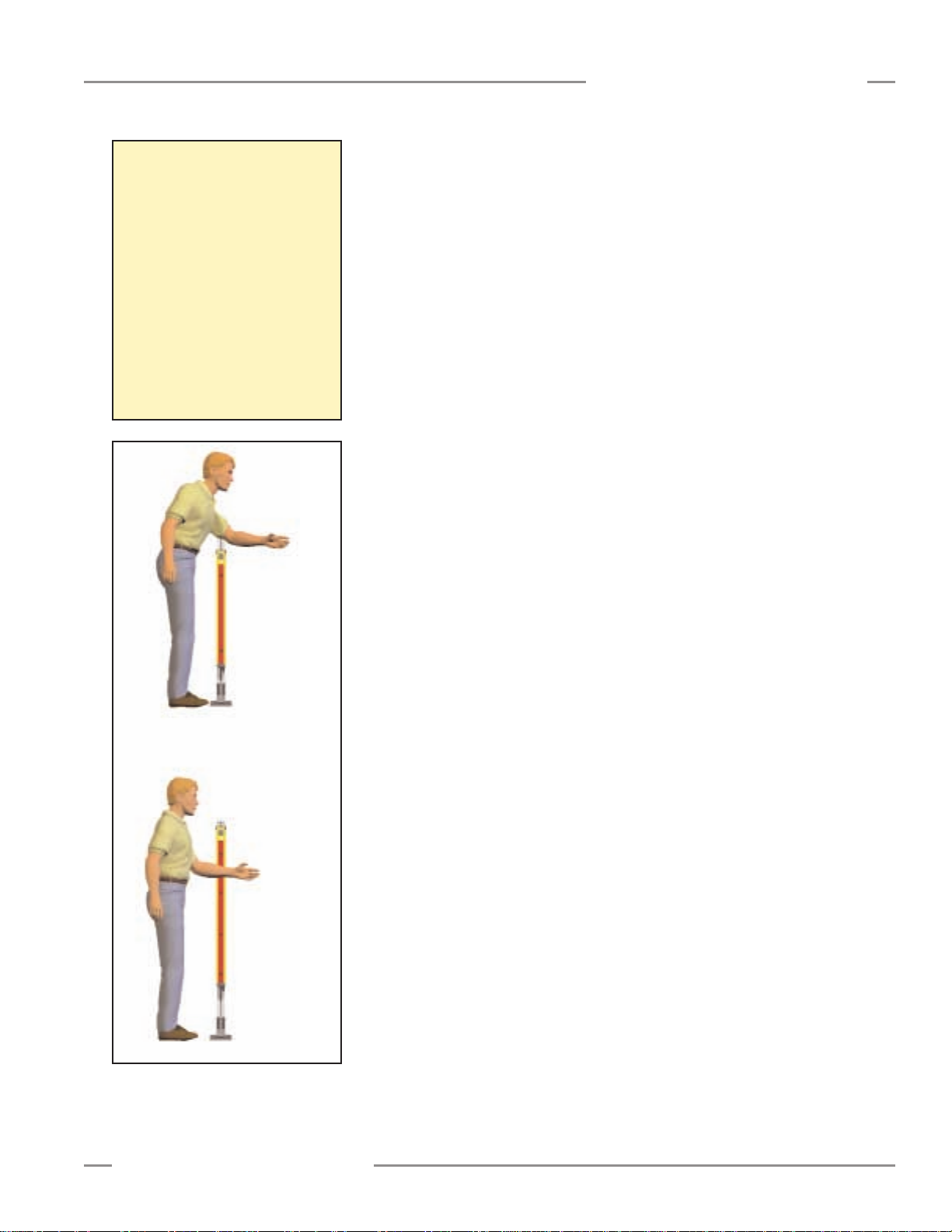
LAT-1 52150 Laser Alignment Tool with adapter clip
EZA-LAT-1 66027 Clip-on retroreflective target
BT-1 26809 Beam Tracker
SI-QS-CG13 48564 Pg13.5 cable gland
SI-QM-13 48559 Adapter, 1/2" NPT to Pg13.5
Interface Modules provide
isolated safety contacts for a
Primary Safety Device (the
EZ-SCREEN Grid System).
See data sheet p/n 62822 for
more information.
* Hard-wired models only are listed. Add the suffixes listed below for quick-disconnect models; see pages 57-58
for more information.
Emitter suffix Q3: 3-pin Mini-style QD, Test input jumpered
Emitter suffix Q5: 5-pin Mini-style QD, Test input available
Receiver suffix Q8: 8-pin Mini-style QD
BRT-THG-2-100 26620 50 mm (2") wide reflective tape, 2.5 m (100") long
SI-QM-13-M20 66579 Adapter, M20 to Pg13.5
CAUTION . . .
Proper Model
Selection
Ensure proper
selection of emitter models,
with respect to range (operating
distance) between emitter and
receiver, to minimize the
possibility of optical short circuits
(see Section 3.3.4).
IM-T-9A 61425
Interface Module (3 normally open redundant-output
contacts)
IM-T-11A 61424
Interface Module (2 normally open redundant-output
contacts plus 1 normally closed auxiliary output contact)
!

page 11
Banner Engineering Corp. • Minneapolis, MN U.S.A.
www.bannerengineering.com • Tel: 763.544.3164
System Components
EZ-SCREEN Grid
Instruction Manual
Model
Part
Number Fits EZ-SCREEN Models
EZS-684 61949 SG..E/R2-500
EZS-768 61950 SG..E/R2-584
EZS-984 61951 SG..E/R3-400
EZS-1251 61952 SG..E/R3-533
EZS-1084 61953 SG..E/R4-300
1084 mm
1251 mm
984 mm
768 mm
684 mm
Length
Lens Shields
NOTE: The total range decreases by approximately 10% per shield.
Mirrors
NOTE: The total range decreases by approximately 8% per mirror.
Accessory Mounting Brackets
NOTE: EZA-MBK-1 Standard end cap bracket kit is included with emitter and receiver.
See Appendix page 59 for accessory bracket dimensions.
Model
Part
Number
Fits EZ-SCREEN
Models
SSM-550 61895 SG..2-500
SSM-675 61896 SG..2-584
SSM-975 61898
SG..3-400
SG..4-300
SSM-1175 61899 SG..3-533
1175 mm
(46.3")
975 mm
(38.4")
675 mm
(26.6")
550 mm
(21.7")
Length
Y L3L2L1
603 mm
(23.7")
628 mm
(24.7")
661 mm
(26")
728 mm
(28.7")
753 mm
(29.6")
786 mm
(31")
1028 mm
(40.5")
1053 mm
(41.5")
1086 mm
(42.8")
1228 mm
(48.3")
1253 mm
(49.3")
1286 mm
(50.6")
61947
Adapter Bracket Kit for MSA Series
Stands
61980 Side-Swivel Bracket Kit
62771
Retrofit Bracket Kit
(to replace SICK/Leuze Grid systems)
66013 Adjustable Bracket Kit
Part
Number
Description
L1
L3
L2
Y
101.2 mm
(3.98")
100 mm
(3.94")
115 mm
(4.53")
M6 x 19 mm screw
(4 supplied)
M5 x 10 mm screw
(4 supplied)
EZA-MBK-2
EZA-MBK-3
EZA-MBK-8
EZA-MBK-9
Model

page 12
Banner Engineering Corp. • Minneapolis, MN U.S.A.
www.bannerengineering.com • Tel: 763.544.3164
System Components
EZ-SCREEN Grid
Instruction Manual
2.3 Replacement Parts
2.4 Literature
MGA-KS0-1 30140 Keyed reset switch (same as that included in kits)
MGA-K-1 28513 Replacement key for switch MGA-KS0-1
EZA-AP-1 62859 Access port plug with o-ring
EZA-CP-13 62860 Pg13.5 plug with o-ring
EZA-ECR-1 62857
Receiver wiring chamber end cap (with gasket, captive
screws, 3 plugs with o-rings, terminal block)
Model
Part
Number Description
EZA-ECE-1 62858
Emitter wiring chamber end cap (with gasket, captive
screws, 3 plugs with o-rings, terminal block)
EZA-TBE-1 62861 Emitter terminal block
EZA-TBR-1 62862 Receiver terminal block
EZA-SW-1 62863 Spanner wrench
EZA-MBK-1 60630 Standard end cap bracket kit (with hardware)
STP-3 43958 Test Piece, 1.75" dia.
60632 Manual
60633 Daily Checkout Card
60634 Semi-Annual Checkout Card
MSA Series Stands
MSA-S42-1 43175 42"
MSA-S66-1 43176 66"
SSM-550, SSM-675
SSM-975, SSM-1175
To Fit Mirror ModelsModel
Part
Number
Height
SG..2-584, SG..2-500
SG..3-533, SG..3-400,
SG..4-300
To Fit Sensor Models
SMA-MBK-1 61933 SSM Series Mirror Bracket Kit
NOTE: One EZA-MBK-2 Adaptor Bracket Kit required per sensor
Usable
Stand
Height
6.4 mm (0.25")
Pole
40 mm
(1.58") Square
(4) M10 Bolt
Base

EZ-SCREEN Grid System Specifications
page 13
Banner Engineering Corp. • Minneapolis, MN U.S.A.
www.bannerengineering.com • Tel: 763.544.3164
Specifications
EZ-SCREEN Grid
Instruction Manual
2.5 Specifications
EDM Input
+24V dc signals from external device contacts can be monitored (single-channel, dualchannel or no monitoring) via EDM1 and EDM2 terminals in the receiver (see Section 3.7.3).
Monitored devices must respond within 200 milliseconds of an output change.
Outputs
(See Warnings on page 33.)
Two diverse-redundant solid-state 24V dc, 0.5 A max. sourcing OSSD (Output Signal
Switching Device) safety outputs. (Use optional interface modules for ac or larger dc loads.)
Capable of the Banner “Safety Handshake” (see Section 1.1).
ON-State voltage: ≥Vin-1.5V dc
OFF-State voltage: 1.2V dc max.
Max. load resistance: 1000 ohm
Max. load capacitance: 0.1µF
Controls and Adjustments
Emitter:
Scan code selection: 2-position switch (code 1 or 2). Factory default position is 1.
Receiver:
Scan code selection: 2-position switch (code 1 or 2). Factory default position is 1.
Trip/latch output selection: redundant switches. Factory default position is L (latch).
EDM/MPCE monitor selection: redundant switches select between 1- or 2-channel
monitoring. Factory default position is 2.
Supply Voltage (V in)
24V dc ±15%, 10% maximum ripple
Emitter: 150 mA max.
Receiver: 500 mA max., exclusive of OSSD1 and OSSD2 loads (up to an additional 0.5A each)
Short Circuit Protection
All inputs and outputs are protected from short circuits to +24V dc or dc common
(except Emitter AUX power connections; see Section 3.5)
Response Time 24 milliseconds or less from interruption of light grid beam to safety outputs going to OFF-state
Safety Rating Type 4 per IEC 61496-1, -2; Category 4 per ISO 13849-1/EN 954-1
Reset Input
The Reset input must be high (10 to 30V dc at 30 mA) for 0.25 to 2 seconds and then low
(less than 3V dc) to reset the receiver.
Remote Test Input
Test mode is activated either by applying a low signal (less than 3V dc) to emitter TEST1
terminal for a minimum of 50 milliseconds, or by opening a switch connected between
TEST1 and TEST2 terminals for a minimum of 50 milliseconds. Beam scanning stops to
simulate a blocked condition. A high signal (10 to 30V dc, 35 mA inrush, 10 mA max.) at
TEST1 terminal de-activates Test mode and allows the emitter to operate normally. TEST1 and
TEST2 are factory jumpered. (See Section 3.7.4 for more information.)
Emitter/Receiver Operating Range
(See Caution on page 6.)
Short-range models: 0.8 m to 20 m (2.6' to 65')
Long-range models: 15 m to 70 m (49' to 230')
Range decreases with use of mirrors and/or lens shields; see Section 2.2.
Beam Spacing
(See dimension drawing, Figure 2-1,
for beam locations.)
Model SG...4-300: 300 mm (11.8")
Model SG...3-400: 400 mm (15.7")
Model SG...2-500: 500 mm (19.7")
Model SG...3-533: 533.4 mm (21")
Model SG...2-584: 584.2 mm (23")
Beam Diameter 25 mm (1")
Ambient Light Immunity > 10,000 lux at 5° angle of incidence
Strobe Light Immunity Totally immune to one Federal Signal Corp. “Fireball” model FB2PST strobe
Emitter Elements Infrared LEDs, 880 nm at peak emission

EZ-SCREEN Grid System Specifications (continued)
page 14
Specifications
EZ-SCREEN Grid
Instruction Manual
Effective Aperture Angle
(EAA)
Meets Type 4 requirements per IEC 61496-2, Section 5.2.9
Short-range models: ±2.5°@ 3 m
Long-range models: ±2.5°@ 15 m
Shock and Vibration
EZ-SCREEN systems have passed vibration and shock tests according to IEC 61496-1 and -2.
This includes vibration (10 cycles) of 10-55 Hz at 0.35 mm (0.014") single amplitude
(0.70 mm peak-to-peak) and shock of 10 g for 16 milliseconds (6,000 cycles).
Enclosure
Size: See Figure 2-1
Materials: Extruded aluminum housings with yellow polyester powder finish and well-sealed,
rugged molded PBT end caps, acrylic lens cover
Rating: NEMA 4, 13; IEC IP65
Operating conditions
Temperature: 0° to +50° C (+32° to 122°F)
Max. Relative Humidity: 95% maximum relative humidity (non-condensing)
Status Indicators
7-Segment Diagnostic Indicators, Both Emitter and Receiver
Dash (–) = System is OK
Error Codes = See Section 5.1 for code definitions and recommended action
Scan code setting = Appears during power-up or after scan code is changed.
(C1 or C2) (Temporary indication; normal display resumes within a few
seconds.)
Emitter: One bi-color (red/green) Status indicator
Green steady = RUN mode
Green single flashing = TEST mode
Red single flashing = Lockout (see Section 5.1.2)
OFF = No power to sensor
Receiver: Two system Status indicators, plus one bi-color (red/green) Beam Status indicator
for each beam
Yellow Reset Indicator
ON steady = RUN mode
Double flashing = Waiting for manual reset after power-up
Single flashing = Waiting for manual latch reset
OFF = No power to sensor or system is not ready for operation
Bi-Color (Red/Green) Status Indicator
Green steady = Outputs ON
Red steady = RUN mode, outputs OFF
Red single flashing = Lockout (see Section 5.1.1)
OFF = No power to sensor or system is not ready for operation
Bi-Color (Red/Green) Beam Status Indicators
Green steady = Clear beam, strong signal
Green flickering = Clear beam, weak signal
Red steady = Beam blocked
OFF = No power to sensor or no scanning
See Figure 1-5 for indicator locations.
Mounting Hardware
Emitter and receiver each are supplied with a pair of swivel end mounting brackets. Mounting
brackets are 8-gauge cold-rolled steel, black zinc finish.
Cables and Connections
Cables are user-supplied. Wiring terminals accommodate one 22 to 16 ga. wire or two wires
up to 18 ga.; Pg13.5 wiring chamber access port capacity varies, depending on cable gland
or strain relief fitting used. Supplied cable gland is for a cable diameter of 6 to 12 mm
(0.236" to 0.472").
Certifications
LISTED
US
Banner Engineering Corp. • Minneapolis, MN U.S.A.
www.bannerengineering.com • Tel: 763.544.3164
Other certifications pending; contact factory for further information

page 15
Banner Engineering Corp. • Minneapolis, MN U.S.A.
www.bannerengineering.com • Tel: 763.544.3164
Specifications
EZ-SCREEN Grid
Instruction Manual
Figure 2-1. EZ-SCREEN dimensions (standard end-cap brackets shown) and EZA-MBK-1 mounting bracket dimensions
Model
Beam
Spacing
L4
Housing
Length
SG..2-584
584 mm
(23")
768 mm
(30.8")
SG..3-533
533 mm
(21")
1251 mm
(49.2")
SG..2-500
500 mm
(19.7")
684 mm
(26.9")
SG..3-400
400 mm
(15.7")
984 mm
(38.7")
Distance Between
Brackets
L1 L2 L3
1017 mm
(40.1")
717 mm
(28.2")
1284 mm
(50.6")
802 mm
(31.6")
743 mm
(29.3")
1226 mm
(48.3")
659 mm
(25.9")
959 mm
(37.8")
SG..4-300
300 mm
(11.8")
1084 mm
(42.7")
1117 mm
(44")
1059 mm
(41.7")
74.2 mm
(2.92")
4.2 mm
(0.17")
25.0 mm
(0.98")
60.0 mm
(2.36")
40 mm
(1.57")
ø 32.0 mm
(1.26")
ø 43.0 mm
(1.69")
2x 30.0°
2x 60.0°
4x 5.8 mm
(0.23")
5.0 mm
(0.20")
15.0 mm
(0.59")
3x 7.0 mm
(0.28")
15.8 mm
(0.62")
31.5 mm
(1.24")
C
L
C
L
EZ-SCREEN
Standard Mounting Bracket
EZA-MBK-1
See page 11 for information
about other accessory brackets.
NOTE: QD models have identical mounting dimensions.
Allow additional height for QD fitting:
69 mm (2.7” for emitters (3- or 5-pin)
89 mm (3.5”) for receivers (8-pin)
2.6 Dimensions
Figure 2-1 shows the dimensions of the five basic configurations, including the
placement of the individual beams. Note that beam spacing varies from model to
model; the beam spacing selected depends on the specific standard(s) being
satisfied for the individual application.
12.5 mm (0.50")
Minimum Bend Radius
L1
16.7 mm
(0.66")
26 mm
(1.02")
107.0 mm
(4.21")
L4
EZ-SCREEN Grid
BANNER ENGINEERING CORP., USA
888.373.6767
1
2
BEAMS
R
E
S
E
T
See Notes
Below
EZ-SCREEN Grid
BANNER ENGINEERING CORP., USA
888.373.6767
52 mm
S
T
A
T
U
S
L2
25 mm
(1.0")
(2.0")
1
2
BEAMS
S
R
T
E
A
S
T
E
U
T
S
55 mm
(2.1")
L3
60.0 mm
(2.36")
74.2 mm
(2.92")

page 16
Banner Engineering Corp. • Minneapolis, MN U.S.A.
www.bannerengineering.com • Tel: 763.544.3164
Installation and Alignment
EZ-SCREEN Grid
Instruction Manual
3. Installation and Alignment
Read Section 3 in its entirety before installing the Banner EZ-SCREEN Grid
System. The Banner EZ-SCREEN Grid System’s ability to perform its safety
guarding function depends upon the appropriateness of the application and upon
its proper mechanical and electrical installation and interfacing to the guarded
machine. If all mounting, installation, interfacing, and checkout procedures are
not followed properly, the EZ-SCREEN Grid System cannot provide the protection
for which it was designed. Installation must be performed by a Qualified Person,
as defined in the Safety Glossary in this manual. See Warning at right.
3.1 Appropriate Applications
The Banner EZ-SCREEN Grid System may be used to guard only machinery that
can be stopped immediately after a stop signal is issued. It may be used with
part-revolution clutched machines that have the ability to stop at any point in
their stroke. Under no circumstances may the EZ-SCREEN Grid System be used
to guard full-revolution clutched machinery. Banner EZ-SCREEN Grid Systems
may not be used as tripping devices to initiate machine motion (PSDI
applications) on mechanical power presses, per OSHA regulation 29 CFR
1910.217.
The Banner EZ-SCREEN Grid System is typically used in access-guarding or
perimeter-guarding applications for the following types of machines:
• Assembly stations
• Manufacturing cells
• Automated production equipment
• Robotic work cells
The Banner EZ-SCREEN Grid System may not be used in the following types of
applications:
• For finger or hand detection in point-of-operation guarding; its beam spacing is
larger than that allowed for finger or hand detection in these applications,
• For non-vertical area-guarding applications,
•To guard any machine that cannot be stopped immediately after a stop signal
is issued, such as single-stroke (or “full-revolution”) clutched machinery,
•To guard any machine with inadequate or inconsistent machine response
time and stopping performance,
•To guard any machine that ejects materials or component parts through the
area protected by the EZ-SCREEN Grid, or
• In any environment that is likely to adversely affect photoelectric sensing
system efficiency. For example, corrosive chemicals or fluids or unusually
severe levels of smoke or dust, if not controlled, may degrade the efficiency of
the safety light grid.
WARNING . . .
Read this Section
Carefully Before
Installing the
System
The user is responsible for
satisfying all local, state, and
national laws, rules, codes, or
regulations relating to the
installation and use of this control
system in any particular
application. Extreme care should
be taken to meet all legal
requirements and follow all
technical installation and
maintenance instructions contained
in this manual.
The user has the sole
responsibility to ensure that the
Banner EZ-SCREEN Grid System is
installed and interfaced to the
guarded machine by Qualified
Persons in accordance with this
manual and applicable safety
regulations.
Read all of Section 3 of this
manual carefully before installing
the system. Failure to follow these
instructions could result in serious
bodily injury or death.
CAUTION . . .
Install System Only
on Appropriate
Applications
In order for the machinery guarded
by the EZ-SCREEN Grid system to
be stopped as described, that
machinery must be capable of
stopping at any point in its
machine cycle. This means that the
EZ-SCREEN Grid system cannot be
used with certain types of
machinery (see listing at left).
If there is any doubt about whether
or not your machinery is
compatible with the EZ-SCREEN
Grid system, contact a Banner
factory application engineer.
!
!

page 17
Banner Engineering Corp. • Minneapolis, MN U.S.A.
www.bannerengineering.com • Tel: 763.544.3164
Installation and Alignment
EZ-SCREEN Grid
Instruction Manual
3.2 Security Protocol
Certain procedures for installing, maintaining and operating the EZ-SCREEN Grid
system must be performed by either Designated Persons or Qualified Persons.
A Designated Person is identified and designated in writing, by the employer, as
being appropriately trained and qualified to perform the specified checkout
procedures on the EZ-SCREEN Grid system. A machine operator so designated
may be a Designated Person. The Designated Person is empowered to:
• Perform manual resets and hold possession of the reset key, and
• Perform the Daily Checkout Procedure (see Section 6).
A Qualified Person, by possession of a recognized degree or certificate of
professional training, or by extensive knowledge, training and experience, has
successfully demonstrated the ability to solve problems relating to the installation
of the EZ-SCREEN Grid System and its integration with the guarded machine. In
addition to everything for which the Designated Person is empowered, the
Qualified Person is empowered to:
• Install the safety light grid system,
• Perform all safety light grid checkout procedures (see Section 6),
• Have access and make changes to the internal light grid configuration settings
and hold possession of the Banner spanner wrench that opens the
configuration access port plug, and
• Reset the system following a lockout condition.
Resetting the System
System resets are performed using an external Reset switch. This switch must be
located outside the guarded area, and not within reach of anyone inside the
guarded area (see Section 3.4). Its location should provide a clear view of the
entire safeguarded area. If any hazardous areas are not within view from the
switch location, additional means of safeguarding must be provided.
The switch should be protected from accidental or unintended actuation (e.g.,
through the use of rings or guards).
If supervisory control of the Reset switch is required, a key switch may be used,
with the key kept in the possession of a Designated or Qualified Person. Using a
key switch will also provide some level of personal control, since the key may be
removed from the switch. This will hinder a reset while the key is under the
control of an individual, but must not be relied upon solely to guard against
accidental or unauthorized reset. Spare keys in the possession of others or
additional personnel entering the safeguarded area unnoticed may create a
hazardous situation.
Reset Routine
The EZ-SCREEN requires a manual reset to clear a latch condition and resume
operation following a stop command. To perform a manual reset, close the
normally open Reset switch for a least 1/4 second, but not longer than 2
seconds, and then re-open the switch. Internal lockout conditions also require a
manual reset to return the system to RUN mode after the failure has been
corrected and the input correctly cycled.

page 18
Banner Engineering Corp. • Minneapolis, MN U.S.A.
www.bannerengineering.com • Tel: 763.544.3164
Installation and Alignment
EZ-SCREEN Grid
Instruction Manual
3.3 Mechanical Installation Considerations
Two factors have the greatest influence on the mechanical installation of the
EZ-SCREEN System:
• The required separation (safety) distance, and
• The presence of hard guarding.
3.3.1 Minimum Separation Distance (Ds)
Minimum Separation (Safety) Distance (Ds) is the minimum distance required
between the light grid and the closest reachable hazard point. Separation distance
is calculated so that the EZ-SCREEN Grid System will send a stop signal to the
machine when an object or a person is detected (by blocking a sensing beam),
allowing the machine to come to a stop by the time the person can reach any
machine hazard point.
After the Dsis determined, record the calculated distance in Section 6.4 (step
2) of this manual, and/or on the Daily Checkout Card.
Figure 3-1. Separation distance
D
s
D
s
D
s
Hazard
page 19
Banner Engineering Corp. • Minneapolis, MN U.S.A.
www.bannerengineering.com • Tel: 763.544.3164
Installation and Alignment
EZ-SCREEN Grid
Instruction Manual
Calculation of separation distance takes into account several factors, including a
calculated human speed, the total system stopping time (which itself has several
components), and the depth penetration factor. The formula used to calculate
separation distance is:
Ds= K x(Ts+ Tr) + D
pf
where:
D
s
= the separation distance, in inches;
K = 63" per second (or 1600 mm per second), the OSHA-recommended (or
EN 999-recommended) hand-speed constant1;
T
s
= the overall stop time of the machine (in seconds) from the initial “stop”
signal to the final ceasing of all motion (including stop times of all
relevant control elements, and measured at maximum machine
velocity)2. See the Warnings on page 20, and the Notice Regarding
MPCEs (at left).
This measurement must take into account the slower of the two MPCE
channels, and the response time of all devices or controls (such as
interface modules) that react to stop the machine. If all devices are not
included, the calculated separation distance (Ds) will be too short and
serious injury could result.
T
r
= 0.024 seconds, the maximum response time of the EZ-SCREEN Grid
System; and
D
pf
= 36" or 48", the added distance due to depth penetration factor (for U.S.
applications, prescribed in ANSI/RIA R15.06 and ANSI B11). Because the
beam spacing of the EZ-SCREEN Grid is larger than 2.5" but less than
24", Dpfis either 36" or 48":
•Dpfis 36" if the top beam is 48" or higher and the bottom beam is
12" or less from the floor (a reach-through hazard).
•Dpfis 48" if the top beam is 36" to 48" above the floor and the
bottom beam is 12" or less from the floor (a reach-over hazard).
In European applications, Dpfis 850 mm, prescribed in EN 999.
NOTES:
1) The OSHA-recommended hand speed constant K has been determined by
various studies, and although these studies indicate speeds of 63"/second to
more than 100"/second, they are not conclusive determinations. The user
should consider all factors, including the physical ability of the operator,
when determining the value of K to be used.
2) Tsis usually measured by a stop-time measuring device. If the machine
manufacturer’s specified stop time is used, at least 20% should be added to
allow for possible clutch/brake system deterioration.
Figure 3-2. Determining Dpf(reach-
through versus reach-over
hazards per ANSI/RIA
R15.06)
Notice Regarding
MPCEs
Each of the two Machine Primary
Control Elements (MPCE 1 and
MPCE2) must be capable of
immediately stopping the dangerous
machine motion, irrespective of the
state of the other. These two channels
of machine control need not be
identical, but the stop time
performance of the machine (Ts, used
to calculate the separation distance)
must take into account the slower of
the two channels.
Reaching Over
Beam 1
Beam 2
Reaching Through
Beam 1
Beam 2
Beam 3
Beam 4

page 20
Banner Engineering Corp. • Minneapolis, MN U.S.A.
www.bannerengineering.com • Tel: 763.544.3164
Installation and Alignment
EZ-SCREEN Grid
Instruction Manual
U.S. Applications:
Using the formula,
Ds= K x(Ts+ Tr) + D
pf
separation distance for a model SG..3-533 EZ-SCREEN Grid System
(42" protected height with 3 beams, 21" apart) is calculated (per ANSI/RIA
R15.06):
K = 63"/second
T
s
= 0.32 (0.250 second is specified by the machine manufacturer; plus
20% safety factor; plus 20 ms for interface module IM-T-9A response)
T
r
= 0.024, the maximum response time of the EZ-SCREEN Grid System
in seconds; and
D
pf
= 36"
Ds= 63 x(0.32 + 0.024) + 36
Ds= 58"
In this example, the EZ-SCREEN Grid emitter and receiver must be mounted
so that no part of the light grid will be closer than 58" from the closest
reachable hazard point of the guarded machine.
European Applications:
Using the same formula, separation distance for a model SG..3-400 EZSCREEN Grid System (800 mm protected height with 3 beams, 400 mm
apart), is calculated (per EN 999):
K = 1600 mm/second
T
s
= 0.32 (0.250 second is specified by the machine manufacturer; plus
20% safety factor; plus 20 ms for interface module IM-T-9A response)
T
r
= 0.024, the maximum response time of the EZ-SCREEN Grid System
in seconds; and
D
pf
= 850 mm
Ds= 1600 x(0.32 + 0.024) + 850
Ds= 1400 mm
In this example, the EZ-SCREEN Grid emitter and receiver must be mounted
so that no part of the light grid will be closer than 1400 mm from the closest
reachable hazard point of the guarded machine.
Figure 3-3. Calculating separation distance, two examples
NOTE: Other machine standards may require different
separation factors from those illustrated. Also,
workers’/operators’ abilities, plant procedures and other
factors may affect Ds.
CAUTION . . .
Position Components
Carefully
The emitter and receiver must be
positioned so that the hazard
cannot be accessed by reaching
over, under, around or through the
sensing field. Supplemental
safeguarding may be required; see
Section 3.3.2.
!
CAUTION . . .
Adequate Separation
Distance
The emitter and receiver must be
positioned a safe distance from
hazardous areas, as described by
OSHA standards in Section
1910.217 (c)(3)(iii)(e). Also see
Section 3.3 of this manual.
Failure to do so could result in
serious bodily injury or death.
CAUTION . . .
Determining Correct
Stop Time
Be sure to include the stop time of
all relevant devices and controls in
your calculations. Failure to do so
could result in serious bodily
injury or death.
!
!
 Loading...