


 Loading...
SureCross Wireless I/O Networks
Instruction Manual
Original Instructions
132607 Rev. J
22 April 2014
132607
SureCross Wireless I/O Networks |
|
|
Contents |
|
|
1 The SureCross® Performance Wireless Network ............................................................. |
5 |
|
1.1 |
SureCross® Performance Gateways and Nodes ............................................................................. |
5 |
1.2 |
SureCross® Performance GatewayPro .......................................................................................... |
5 |
1.3 |
DX83 Ethernet Bridge Overview .................................................................................................. |
5 |
1.4 |
Host Controller Systems ............................................................................................................. |
6 |
1.5 |
What is FlexPower®? ................................................................................................................. |
6 |
1.6 |
SureCross User Configuration Tool ............................................................................................... |
7 |
2 Features ......................................................................................................................... |
8 |
|
2.1 |
DX80 Gateway and Node Components ......................................................................................... |
8 |
2.2 |
DX80 Gateway and Node Wiring Chamber .................................................................................... |
8 |
2.3 |
DX80 GatewayPro ..................................................................................................................... |
9 |
2.4 |
DX83 Ethernet Bridge ................................................................................................................ |
9 |
2.5 |
Wiring Diagrams ..................................................................................................................... |
10 |
|
2.5.1 5-pin Euro-Style Wiring for Gateways and DX85s ............................................................... |
10 |
|
2.5.2 5-pin Euro-Style Wiring for Nodes .................................................................................... |
10 |
|
2.5.3 DX80...C Wiring ............................................................................................................. |
11 |
|
2.5.4 Industrial Ethernet Wiring ............................................................................................... |
11 |
2.6 |
Dimensions ............................................................................................................................ |
11 |
|
2.6.1 Gateways and Nodes ...................................................................................................... |
11 |
|
2.6.2 GatewayPro .................................................................................................................. |
13 |
|
2.6.3 DX83 Ethernet Bridge ..................................................................................................... |
13 |
3 Setting Up Your Wireless Network ............................................................................... |
14 |
|
3.1 |
Using Extended Address Mode ................................................................................................... |
14 |
3.2 |
Mixing Performance and Non-Performance Radios in the Same Network ......................................... |
14 |
3.3 |
Applying Power to the Gateway or Node ..................................................................................... |
15 |
3.4 |
Bind Radios to Form Networks .................................................................................................. |
15 |
3.5 |
LED Behavior for the Gateways ................................................................................................ |
16 |
3.6 |
LED Behavior for the Nodes ...................................................................................................... |
16 |
3.7 |
Conducting a Site Survey (Gateway and Nodes) .......................................................................... |
17 |
|
3.7.1 SITE (Site Survey) Menu ................................................................................................ |
17 |
|
3.7.2 Interpreting the Site Survey Results ................................................................................. |
18 |
|
3.7.3 Site Survey Troubleshooting ............................................................................................ |
19 |
|
3.7.4 Conduct a Site Survey Using Modbus Commands ............................................................... |
19 |
4 Installing Your SureCross® Radios .............................................................................. |
21 |
|
4.1 |
Mounting SureCross Devices Outdoors ...................................................................................... |
21 |
|
4.1.1 Watertight Glands and NPT Ports ..................................................................................... |
21 |
4.2 |
Other Installation Requirements ............................................................................................... |
22 |
4.3 |
Installation Quick Tips ............................................................................................................. |
22 |
|
4.3.1 Create a Clear Communication Path ................................................................................. |
22 |
|
4.3.2 Increase the Height of the Antennas ................................................................................. |
22 |
|
4.3.3 Collocated Radios .......................................................................................................... |
23 |
|
4.3.4 Be Aware of Seasonal Changes ........................................................................................ |
23 |
4.4 |
Basic Remote Antenna Installation ............................................................................................. |
23 |
|
4.4.1 Weatherproof Remote Antenna Installations ...................................................................... |
24 |
|
4.4.2 Antenna Installation ...................................................................................................... |
24 |
|
4.4.3 Mount a Dome Antenna to the Enclosure ........................................................................... |
25 |
|
4.4.4 Use an N-Type, Pole-Mounted Antenna ............................................................................. |
26 |
5 Advanced Setup Instructions and Additional Information ............................................. |
28 |
|
5.1 |
DX80 Menu Structure ............................................................................................................... |
28 |
|
5.1.1 RUN Menu .................................................................................................................... |
31 |
|
5.1.2 DINFO (Device Information) Menu ................................................................................... |
32 |
|
5.1.3 FCTRY (Factory) Menu .................................................................................................... |
33 |
|
5.1.4 SITE (Site Survey) Menu ................................................................................................ |
34 |
|
5.1.5 DVCFG (Device Configuration) Menu ................................................................................. |
35 |
|
5.1.6 DERR (Device Error) Menu .............................................................................................. |
36 |
5.2 |
Web-based Configuration ......................................................................................................... |
37 |
|
5.2.1 Accessing the Web-based Configuration Screens ............................................................... |
38 |
|
5.2.2 Changing the IP Address ................................................................................................. |
39 |
5.3 |
Binding Mode: What does it do? ............................................................................................... |
40 |
5.4 |
More Details About Extended Address Mode ................................................................................ |
40 |
|
5.4.1 Manually Choosing an Extended Address Code - Gateway .................................................... |
41 |
|
5.4.2 Manually Choosing an Extended Address (Binding) Code - Node ........................................... |
41 |
|
5.4.3 Setting the Network ID in Extended Addressing Mode ......................................................... |
42 |
|
5.4.4 Automatic Binding Using the Menu Navigation ................................................................... |
42 |
|
|
SureCross Wireless I/O Networks |
5.5 |
Setting the Maximum System Devices ........................................................................................ |
43 |
5.6 |
Storage Mode and Sleep Mode ................................................................................................. |
43 |
5.7 |
Modbus Communication Parameters ........................................................................................... |
43 |
|
5.7.1 Setting the Slave ID on a DX80 Gateway .......................................................................... |
44 |
|
5.7.2 Setting the Baud Rate .................................................................................................... |
44 |
|
5.7.3 Setting Parity ................................................................................................................ |
44 |
5.8 |
Default Output Conditions ........................................................................................................ |
45 |
|
5.8.1 Host Link Failure ............................................................................................................ |
45 |
|
5.8.2 Gateway Link Failure ...................................................................................................... |
45 |
|
5.8.3 Node Link Failure ........................................................................................................... |
46 |
5.9 |
Units Defined .......................................................................................................................... |
46 |
|
5.9.1 Interpreting Register Values in the Banner Wireless System ................................................ |
49 |
5.10 Setting up the Wireless Network Using the Rotary Dials .............................................................. |
51 |
|
|
5.10.1 Rotary Dial Address Mode ............................................................................................. |
51 |
|
5.10.2 Setting the Network ID Using the Rotary Dials ................................................................. |
51 |
|
5.10.3 Setting the Device Address Using the Rotary Dials ............................................................ |
51 |
|
5.10.4 Setting Up Channel Search Mode ................................................................................... |
52 |
6 System Layouts ............................................................................................................ |
54 |
|
6.1 |
Stand-Alone Systems ............................................................................................................... |
54 |
|
6.1.1 Mapped Pairs (DX70) ..................................................................................................... |
54 |
|
6.1.2 Gateway with Multiple Nodes (DX80) ................................................................................ |
55 |
|
6.1.3 Gateway Configured as a Modbus Master .......................................................................... |
56 |
6.2 |
Modbus RTU ........................................................................................................................... |
57 |
|
6.2.1 Modbus RTU Host Controlled Operation ............................................................................. |
57 |
|
6.2.2 Modbus RTU with Multiple Slave Devices ........................................................................... |
58 |
|
6.2.3 Modbus RTU with Multiple Slave Devices - Layout 2 ............................................................ |
59 |
6.3 |
Modbus/TCP and EtherNet/IP .................................................................................................... |
60 |
|
6.3.1 Host Connected - DX80 GatewayPro ................................................................................. |
60 |
6.4 |
Data Radios ............................................................................................................................ |
61 |
|
6.4.1 Data Radios .................................................................................................................. |
61 |
|
6.4.2 Data Radios with DX85 Modbus RTU Remote I/O Devices .................................................... |
61 |
|
6.4.3 Data Radios with a Gateway as the Modbus Master ............................................................ |
62 |
7 Sensor Connections ...................................................................................................... |
63 |
|
7.1 |
Discrete Inputs ...................................................................................................................... |
63 |
|
7.1.1 Discrete Inputs, Sourcing ................................................................................................ |
63 |
|
7.1.2 Discrete Inputs, Sinking ................................................................................................. |
63 |
|
7.1.3 Discrete Inputs, MINI-BEAM ............................................................................................ |
64 |
7.2 |
Discrete Outputs .................................................................................................................... |
64 |
|
7.2.1 Discrete Outputs ............................................................................................................ |
64 |
7.3 |
Analog Inputs ........................................................................................................................ |
64 |
|
7.3.1 Analog Inputs, Powered using SureCross Device Terminals .................................................. |
64 |
|
7.3.2 Analog Inputs, Powered from Switch Power ....................................................................... |
65 |
|
7.3.3 Analog Inputs, Powered Externally ................................................................................... |
65 |
|
7.3.4 Analog Inputs, Temperature Sensors ................................................................................ |
65 |
|
7.3.5 Analog Inputs, QT50U Long-Range Ultrasonic Sensor ......................................................... |
66 |
7.4 |
Analog Outputs ...................................................................................................................... |
66 |
|
7.4.1 Analog Outputs, Three-Wire Sensors ................................................................................ |
66 |
|
7.4.2 Analog Outputs, Drive Motor Controllers ........................................................................... |
66 |
8 SureCross Power Solutions ........................................................................................... |
67 |
|
8.1 |
10 to 30V dc Power ................................................................................................................. |
67 |
8.2 |
What is FlexPower®? ............................................................................................................... |
67 |
|
8.2.1 Switch Power (with FlexPower) ........................................................................................ |
67 |
|
8.2.2 FlexPower with Integrated Battery ................................................................................... |
68 |
|
8.2.3 FlexPower® Solar Supply ................................................................................................ |
68 |
8.3 |
Battery Life Calculations ........................................................................................................... |
68 |
|
8.3.1 Analog Configuration ...................................................................................................... |
68 |
|
8.3.2 Discrete Configuration .................................................................................................... |
69 |
|
8.3.3 Temperature and Humidity Sensor ................................................................................... |
70 |
|
8.3.4 Calculating Battery Life ................................................................................................... |
71 |
8.4 |
Example Solar Powered Systems ............................................................................................... |
72 |
|
8.4.1 Parallel Solar Systems .................................................................................................... |
73 |
|
8.4.2 Battery Backup Feature .................................................................................................. |
74 |
|
8.4.3 Autonomous Process Monitoring with Continuous Sensor Operation |
...................................... 74 |
|
8.4.4 Wireless Network Range Extension ................................................................................... |
74 |
9 Maintenance ................................................................................................................. |
76 |
|
9.1 |
Replacing the Main Body Gasket ................................................................................................ |
76 |
9.2 |
Replacing the Rotary Dial Access Cover ...................................................................................... |
76 |
9.3 |
Battery Replacement ............................................................................................................... |
76 |
|
9.3.1 Replacing the Battery (DX81 and DX81H Battery Supply Module) |
........................................ 76 |
|
9.3.2 Replacing the Integrated Battery (DX80 Models) ............................................................... |
77 |
SureCross Wireless I/O Networks |
|
|
|
9.3.3 Replacing the Battery (DX99...D Models) ......................................................................... |
77 |
10 Troubleshooting .......................................................................................................... |
79 |
|
10.1 |
Startup Problems ................................................................................................................... |
79 |
10.2 |
LED Message Codes ............................................................................................................... |
79 |
10.3 |
LCD Message Codes ............................................................................................................... |
81 |
|
10.3.1 Modbus Message Codes for Register 8 ............................................................................ |
81 |
10.4 |
Inputs and Outputs ................................................................................................................ |
82 |
10.5 |
Radio Link Time-Out and Recovery (Non-Host Connected Systems) .............................................. |
82 |
11 SureCross Accessories ................................................................................................ |
84 |
|
11.1 |
Accessories ........................................................................................................................... |
84 |
|
11.1.1 Selecting an Enclosure ................................................................................................. |
84 |
|
11.1.2 Selecting an Antenna ................................................................................................... |
86 |
|
11.1.3 Power Supplies ............................................................................................................ |
89 |
|
11.1.4 Relays ....................................................................................................................... |
90 |
|
11.1.5 Brackets and Mounting Options ..................................................................................... |
91 |
|
11.1.6 Other Accessories ........................................................................................................ |
92 |
12 Radio Certifications .................................................................................................... |
99 |
|
12.1 |
FCC Certification, 900MHz ....................................................................................................... |
99 |
12.2 |
FCC Certification, 900 MHz, 1 Watt Radios ............................................................................... |
100 |
12.3 |
FCC Certification, 2.4GHz ...................................................................................................... |
101 |
12.4 |
Certified For Use in the Following Countries ............................................................................. |
102 |
12.5 |
Exporting SureCross Radios ................................................................................................... |
104 |
13 Warnings ................................................................................................................. |
105 |
|
13.1 |
Banner Engineering Corp Limited Warranty ............................................................................ |
105 |
13.2 |
Contact Us ......................................................................................................................... |
105 |
SureCross Wireless I/O Networks
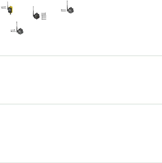
1 The SureCross® Performance Wireless Network
Node
FlexPower Node with integrated battery
Gateway
Node
The SureCross® Performance wireless I/O network provides reliable monitoring without wiring or conduit installation. The SureCross wireless network operates independently or in conjunction with a host system, PLC, and/or PC software.
Each wireless network system consists of one Gateway and one or more Nodes. Devices ship with factory-defined discrete, analog, or a mix of discrete and analog inputs and outputs.
The SureCross® Performance network is a deterministic system—the network identifies when the radio signal is lost and drives relevant outputs to user-defined conditions. After the radio signal is reacquired, the network returns to normal operation.
1.1 SureCross® Performance Gateways and Nodes
Every wireless network must have one Gateway, which schedules communication traffic and controls the I/O configuration for the network, and one or more Nodes.
A Gateway is the master device within each radio network. Similar to how a gateway device on a wired network acts as a “portal” between networks, the SureCross Gateway acts as the portal between the wireless network and the host controller. When the Gateway, using its Modbus RTU RS-485 connection, is a Modbus slave to a Modbus RTU host controller, the wireless network may contain up to 47 Nodes in a single wireless network. The Gateway holds the Modbus registers of all wireless devices within the network.
A Node is a wireless network end-point device used to provide sensing capability in a remote area or factory. The Node collects data from sensors and communicates the data back to the Gateway. Nodes are available in a wide variety of power or input/output options.
1.2 SureCross® Performance GatewayPro
The SureCross® Performance GatewayPro combines the function of a SureCross® Performance Gateway with the ability to interface to Ethernet using Modbus/TCP or EtherNet/IP™ protocols.
There are two basic models of the GatewayPro:
•DX80P*T6*. The T6 model acts as a protocol converter only, offering the Modbus/TCP or EtherNet/IP communication protocols.
•DX80P*A6*. The A6 model includes DX80 wireless network configuration, Modbus RTU master, Modbus/TCP client/server, Script Basic, e-mail, data logging, and trending.
Connect a host controller system to the GatewayPro using its industrial Ethernet connection. To connect the GatewayPro to the host system without using an Ethernet switchbox/hub, some host systems may require a crossover cable.
By default, the GatewayPro is configured to use Modbus/TCP. To use EtherNet/IP, connect the GatewayPro to a managed switch and you must use the Web Configuration tool to select EtherNet/IP. For more information, see SureCross Wireless I/O Product Manual or Host Configuration Manual.
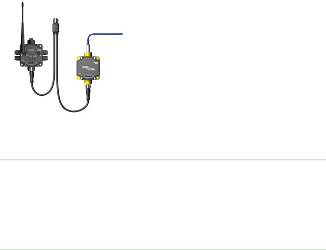
1.3 DX83 Ethernet Bridge Overview
A DX83 Ethernet Bridge connected to a DX80 Gateway functions like a DX80 GatewayPro and allows the Gateway to have I/O points. The DX83 Ethernet Bridge adds the Web page configuration ability to a Gateway-Node wireless network as well as the ability to interface to Ethernet using Modbus/TCP or EtherNet/IP protocols.
There are two basic DX83 models:
•DX83T acts as a protocol converter only, offering the Modbus/TCP or EtherNet/IP communication protocols.
•DX83A includes DX80 wireless network configuration, Modbus RTU master, Modbus/TCP client/server, Script Basic, e-mail, data logging, and trending.
5
SureCross Wireless I/O Networks
Power
Gateway
Ethernet cable (crossover cable when connecting to a computer; straight cable when connecting to a hub or switch box)
DX83 Ethernet Bridge
CSRB-M1250M125.47M125.73 5-pin splitter cable (black); OR CSB-M1240M1241 4-pin splitter cable (yellow)
1.4 Host Controller Systems
Connect a DX83 Ethernet Bridge to a host system using the industrial Ethernet connection on the DX83. To connect the DX83 directly to the host system without using an Ethernet switchbox/hub, some host systems may require a crossover cable.
By default, the DX83 is configured to use Modbus/TCP. To use EtherNet/IP, you must connect the DX83 to a managed switch and you must use the Web Configuration tool to select EtherNet/IP (see SureCross Wireless I/O Product Manual or Host Configuration Manual).
Host controller systems collect I/O data for logging, controlling other devices, or performing calculations.
Host controller systems can contain up to 15 Nodes (when using Rotary Dial Addressing Mode) or 47 Nodes (when using Extended Addressing Mode) within a single network. Inputs from Nodes within the network are transmitted to the Gateway, which communicates the information to a host system for processing. Although the Gateway is the master device within the radio network, it may be a slave to the Modbus network.
Host controlled DX80 wireless systems are configured using an Ethernet network connection and a Web page browser. An Ethernet connection can be established from a DX80 GatewayPro or a DX83 Ethernet Bridge serially connected to the DX80 Gateway.
1.5 What is FlexPower®?
Banner’s FlexPower technology supplies a true wireless solution by allowing the device to operate using either 10–30V dc, 3.6V lithium D cell batteries, or solar power. This unique power management system can operate a FlexPower Node and an optimized sensing device for up to five years on a single lithium D cell.
•FlexPower Nodes may be powered from 10–30V dc and use an external battery supply module to provide a battery back-up solution.
•When a FlexPower Node receives 10–30V dc, it operates like a standard 10–30V dc Node.
•Good applications for FlexPower devices operating from batteries include sensors that require no or very little power, including dry contacts, RTDs, and thermocouples.
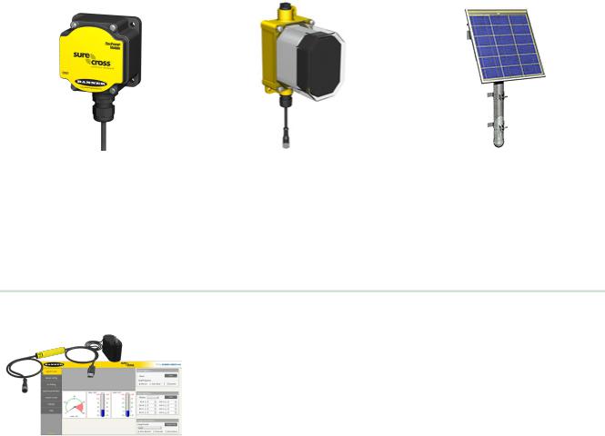
The following FlexPower options are available:
•DX81, a single battery supply module;
•DX81P6, a 6-pack of lithium batteries;
•DX81H, a single battery supply module designed specifically to power the DX99 Intrinsically Safe devices with polycarbonate housings; and
•BWA-SOLAR-001, a solar power assembly that includes the solar panel, rechargeable batteries, and solar power controller.
6
SureCross Wireless I/O Networks
DX81: Single battery supply module |
DX81P6: Six-pack battery supply |
BWA-SOLAR-001: Solar supply; |
DX81H: Single battery supply module |
module |
includes solar panel, rechargeable |
|
batteries, and controller. |
|
designed specifically to power the |
|
|
DX99 Intrinsically Safe devices with |
|
|
polycarbonate housings |
|
|
1.6 SureCross User Configuration Tool
The User Configuration Tool (UCT) software runs on any Windows machine and uses a converter cable to connect your Gateway to the computer.
The User Configuration Tool (UCT) offers an easy way to link I/O points in your wireless network, view I/O register values graphically, and set system communication parameters when a host system is not part of the wireless network. Download the most recent revisions of the UCT software from Banner Engineering's website: http://www.bannerengineering.com/wireless.
The UCT requires a special USB to RS-485 (model number BWA-UCT-900 for 1 Watt radios, BWA-HW-006 can be used for all other radios) converter cable to pass information between your computer and the Gateway.
7
SureCross Wireless I/O Networks
2 Features
The following feature callouts refer to the DX80 Gateway and Node models, the GatewayPro, and the DX83 Ethernet Bridge. The wiring diagrams include information for connection power and sensors using the 5-pin Euro-style connect, the terminal wiring board, and the Industrial Ethernet connection on the DX83 and GatewayPro.
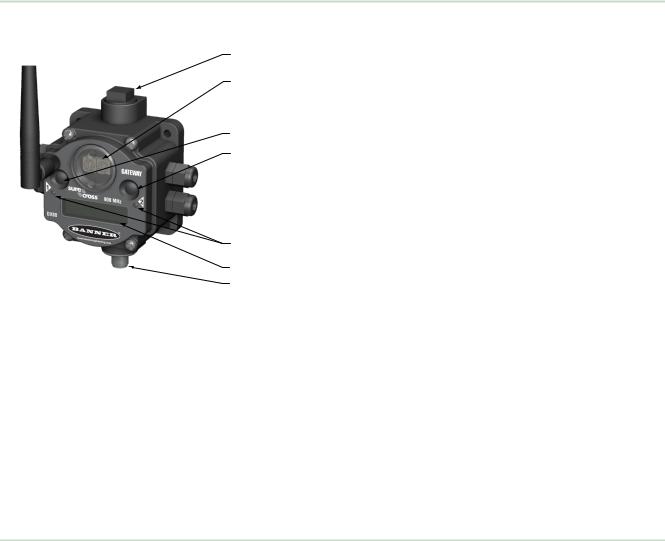
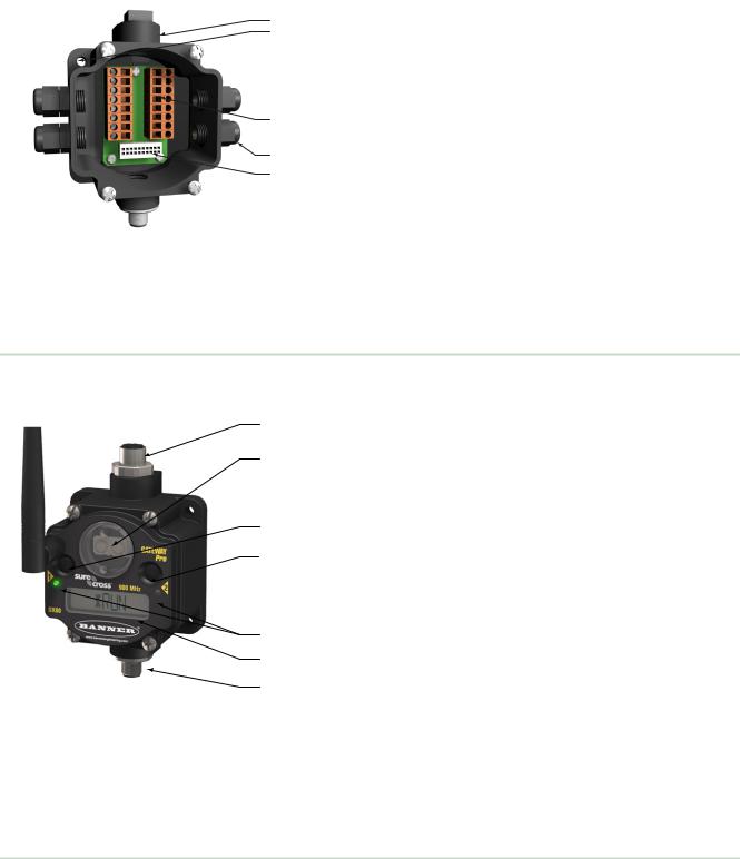
2.1 DX80 Gateway and Node Components
The DX80 Gateway and Node use the same housing and include the same physical features.
11. Port, NPT gland, or plug. If unused, install the provided plug into the 1/2 NPT threaded port. Refer to the Installation
2section if an IP67 seal is required.
2. Rotary switch 1 (left). Sets the Network ID (NID) to a
|
hexidecimal value from 0 to F, for a total of 16 Network IDs. A |
3 |
Gateway and its corresponding Nodes must be assigned the |
same Network ID. |
4
Rotary switch 2 (right). On the Gateway, sets the Gateway’s LCD viewing device address. The Gateway is predefined as Device Address 0. On the Node, sets the Node’s Device Address (hexidecimal 1 to F). Each Node within a network must have a unique Node Device Address.
53. Push button 1. Single-click to advance across all top-level DX80 menus. Single-click to move down interactive menus,
6once a top-level menu is chosen. Button 1 is also used to wake integrated battery models from the hibernation mode they ship
7in.
4. Push button 2. Double-click to select a menu and to enter manual scrolling mode. Double-click to move up one level at a time.
5.LED 1 and 2. Provide real-time feedback to the user regarding RF link status, serial communications activity, and the error state.
6.LCD Display. Six-character display provides run mode user information and shows enabled I/O point status. This display allows the user to conduct a Site Survey (RSSI) and modify other DX80 configuration parameters without the use of a PC or other external software interfaces. On the Node, after 15 minutes of inactivity, the LCD goes blank. Press any button to refresh the display.
7.5-Pin M12 Euro-style quick-disconnect serial port
2.2 DX80 Gateway and Node Wiring Chamber
The DX80 Gateway and Node use the same housing and terminal block for wiring.
8
|
|
SureCross Wireless I/O Networks |
|
1 |
1. |
Housing. The rugged, industrial DX80 housing meets IEC |
|
IP67 standards. |
|||
2 |
|||
|
|
||
|
2. |
Mounting hold, #10/M5 clearance. Mounting Holes accept |
|
|
metric M5 or UNC/UNF #10 hardware -- DIN rail mount |
||
|
adapter bracket available. |
||
3 |
3. |
Wiring terminal strip. The 16 spring-clip type wiring |
|
terminals accept wire sizes: AWG 12-28 or 2.5 sq mm. |
|||
4 |
4. |
Port, PG-7 gland or blank. The PG-7 threaded ports can |
|
accept provided cable glands or blanks. |
|||
5 |
|||
5. |
Ribbon connector. Ribbon cable connects wiring base to |
||
|
|||
|
LCD/radio. |
||
The GatewayPro has no serviceable parts inside the housing and no wiring chamber. During setup or standard operation, there should not be a need to open the GatewayPro.
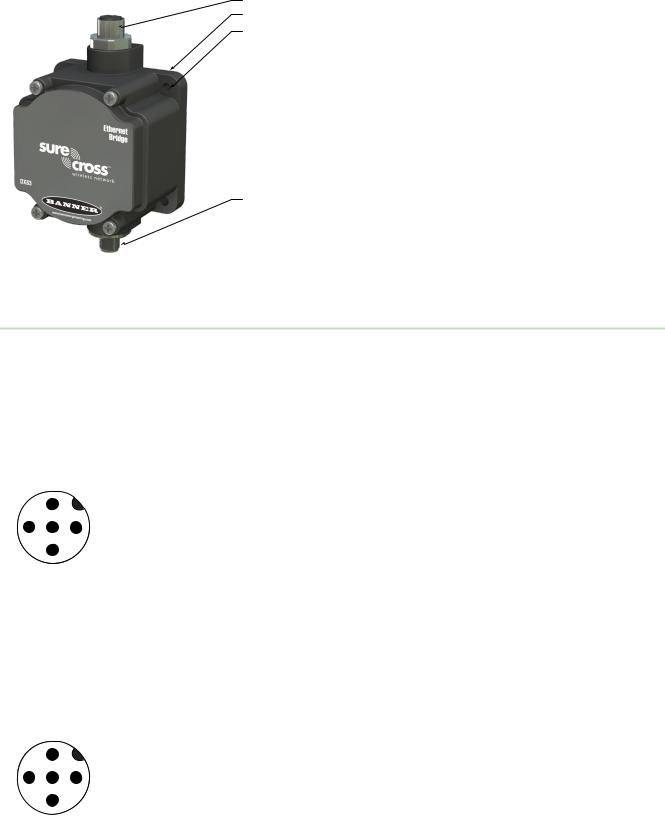
2.3 DX80 GatewayPro
The GatewayPro has many of the same features as the Gateway and Node, including the LEDs, the buttons, LCD, and Euro-style connector.
1. Industrial ethernet port, female.
1
2. Rotary switch 1 (left). Sets the Network ID (NID) to a hexidecimal 2 value from 0 to F, for a total of 16 Network IDs. A Gateway and its
corresponding Nodes must be assigned the same Network ID.
3. Rotary switch 2 (right). On the Gateway, sets the Gateway’s LCD viewing device address. The Gateway is predefined as Device Address 0.
3On the Node, sets the Node’s Device Address (hexidecimal 1 to F). Each Node within a network must have a unique Node Device Address.
43. Push button 1. Single-click to advance across all top-level DX80
menus. Single-click to move down interactive menus, once a top-level menu is chosen.
|
4. |
Push button 2. Double-click to select a menu and to enter manual |
|
5 |
scrolling mode. Double-click to move up one level at a time. |
||
5. |
LED 1 and 2. Provide real-time feedback to the user regarding RF link |
||
6 |
|||
status, serial communications activity, and the error state. |
|||
7 |
6. |
LCD Display. Six-character display provides run mode user |
|
information and shows enabled I/O point status. This display allows the |
|||
|
|||
|
user to conduct a Site Survey (RSSI) and modify other DX80 |
||
|
configuration parameters without the use of a PC or other external |
||
|
software interfaces. On the Node, after 15 minutes of inactivity, the LCD |
||
|
goes blank. Press any button to refresh the display. |
||
|
7. |
5-pin M12 Euro-style quick disconnect serial port. |
|
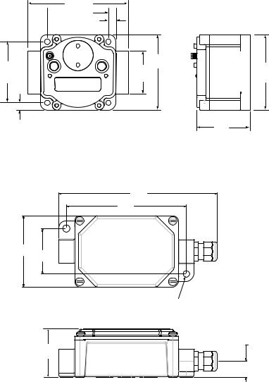
2.4 DX83 Ethernet Bridge
The DX83 Ethernet Bridge uses the same housing and same mounting holes as the Gateway and Node.
9
SureCross Wireless I/O Networks
1
2
3
4
1.Industrial ethernet port, female.
2.Housing. The rugged, industrial DX80 housing meets IEC IP67 standards.
3.Mounting hold, #10/M5 clearance. Mounting Holes accept metric M5 or UNC/UNF #10 hardware -- DIN rail mount adapter bracket available.
4.5-Pin M12 Euro-style quick-disconnect serial port
2.5 Wiring Diagrams
Use the following drawings to correctly wire power and I/O to the SureCross Wireless radio devices. For more information about wiring sensors to the SureCross devices, refer to Sensor Connections.
2.5.1 5-pin Euro-Style Wiring for Gateways and DX85s
Wiring the 5-pin Euro-style connector depends on the model and power requirements of the device. Connecting dc power to the communication pins will cause permanent damage.
|
|
|
|
Wire No. |
Wire Color |
Description |
|
2 |
|
|
1 |
Brown |
10–30V dc |
|
|
|
|
|
|
|
|
|
|
|
2 |
White |
RS485 / D1 / B / + |
3 |
|
|
1 |
3 |
Blue |
dc common (GND) |
|
5 |
4 |
Black |
RS485 / D0 / A / – |
||
|
|
|
||||
|
|
|
|
|||
|
4 |
|
|
5 |
Gray |
Comms Gnd |
|
|
|
|
|
|
2.5.2 5-pin Euro-Style Wiring for Nodes
Wiring the 5-pin Euro-style connector depends on the model and power requirements of the device. Not all models can be powered by 10 to 30 V dc and not all models can be powered by 3.6 to 5.5 V dc. Refer to the Specifications to verify the power requirements of your device. For FlexPower devices, do not apply more than 5.5 V to the gray wire.
|
|
|
|
Wire No. |
Wire Color |
10 to 30 V dc Powered |
Battery Powered |
|
2 |
|
|
1 |
Brown |
10 to 30 V dc |
|
|
|
|
|
|
|
|
|
|
|
|
|
2 |
White |
|
|
3 |
|
|
1 |
3 |
Blue |
dc common (GND) |
dc common (GND) |
|
5 |
4 |
Black |
|
|
||
|
|
|
|
|
|||
|
|
|
|
|
|
||
|
4 |
|
|
5 |
Gray |
|
3.6 to 5.5 V dc |
|
|
|
|
|
|
|
10
SureCross Wireless I/O Networks
2.5.3 DX80...C Wiring
Wiring power to the DX80...C models varies depending the power requirements of the model. Connecting dc power to the communication pins (Tx/Rx) causes permanent damage. For FlexPower devices, do not apply more than 5.5 V to the B+ terminal.
Terminal |
Gateway, DX85 |
10 to 30 V dc Powered Nodes |
Battery Powered Nodes |
Label |
|
|
|
|
|
|
|
V+ |
10 to 30 V dc |
10 to 30 V dc |
|
Tx/+ |
RS485 / D1 / B / + |
|
|
V- |
dc common (GND) |
dc common (GND) |
dc common (GND) |
Rx/- |
RS485 / D0 / A / - |
|
|
B+ |
|
|
3.6 to 5.5 V dc |
2.5.4 Industrial Ethernet Wiring
Use the 4-pin industrial Ethernet connection to connect the radio network to an Ethernet-based host system.
Wire No. |
Wire Color |
Description |
1 |
White/Orange |
+Tx |
2 |
White/Blue |
+Rx |
3 |
Orange |
-Tx |
4 |
Blue |
-Rx |
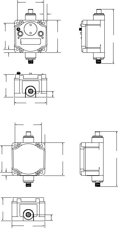
2.6 Dimensions
The DX80, DX83, and DX70 models all share the same housing and mounting hole dimensions.
2.6.1 Gateways and Nodes
|
65.0 |
|
22.2 |
|
[2.56”] |
|
|
|
|
[0.875”] |
|
|
7.9 |
|
|
|
|
|
|
|
[0.31”] |
|
|
|
30.65 |
|
|
|
[1.21”] |
|
|
65.0 |
19 |
80.3 |
|
[2.56”] |
[0.75”] |
[3.16”] |
127 |
|
|
|
[5”] |
|
7.65 |
|
|
|
[0.30”] |
|
|
60
[2.36”]
14.67
[0.578”]
80.8
[3.18”]
120
[4.72”]
11
SureCross Wireless I/O Networks
DX80...C Gateways and Nodes
101.6 [4”]
 65.0 [2.56”]
7.9 [0.31”]
|
80.3 |
65.0 |
[3.16”] |
45.7 |
|
[2.56”] |
[1.8”] |
7.65 [0.30”]
DX80...E Housings
195.9 mm [7.71’’]
148.1 mm [5.83’’]
87.6 mm
[3.45’’] 55.9 mm [2.20’’]
For 1/4” or M7 bolts
60
[2.36”]
80.8
[3.18”]
|
20.1 mm |
59.7 mm |
[0.79’’] |
[2.35”] |
|
12
2.6.2 GatewayPro
65.0
[2.56’’]
7.9
[0.31’’]
65.0 |
80.3 |
[2.56’’] |
[3.16’’] |
7.65
[0.30’’]
60
[2.36’’]
14.67
[0.578’’]
80.8
[3.18’’]
2.6.3 DX83 Ethernet Bridge
65.0
[2.56’’]
7.9  [0.31’’]
65.0 |
80.3 |
[2.56’’] |
[3.16’’] |
7.65
[0.30’’]
60.0
[2.36’’]
14.67
[0.578’’]
80.8
[3.18’’]
SureCross Wireless I/O Networks
136
[5.35’’]
136
[5.35’’]
13
SureCross Wireless I/O Networks
3 Setting Up Your Wireless Network
To set up and install your wireless network, follow these steps.
Disconnect the power from your SureCross devices.
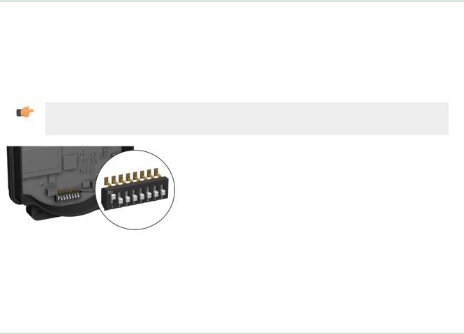
1.Configure the DIP switches of all devices. For DIP switch configurations, refer to the product's datasheet.
2.Connect the sensors to the SureCross devices. For available I/O, refer to the product's datasheet.
3.Apply power to all devices.
On the Gateway, LED 1 is solid green. On the Node, LED 2 flashes red to indicate there is no radio link to the Gateway.
4.Form the wireless network by binding the Nodes to the Gateway.
5.Observe the LED behavior to verify the devices are communicating with each other.
On the Gateway, LED 1 is solid green. On the Node, LED 1 flashes green to indicate it is communicating with the Gateway.
6.Conduct a site survey between the Gateway and Nodes.
7.Install your wireless sensor network components.
3.1Using Extended Address Mode
Using extended address mode isolates networks from one another by assigning a unique code, the extended address code, to all devices in a particular network. Only devices sharing the extended address code can exchange data.
In addition to isolating networks, using extended addressing mode allows you to use up to 47 Nodes with a single Gateway. Without extended addressing, only 15 Nodes can communicate with a single Gateway.
The extended address code in the Gateway defaults to a code derived from its serial number, although the code can be customized using the manual binding procedure. Binding DX80 devices "locks" Nodes to a specific Gateway by teaching the Nodes the Gateway’s extended address code. After the devices are bound, the Nodes only accept data from the Gateway to which they are bound.
Important: All SureCross Performance Gateways and Nodes are preconfigured for extended addressing mode and cannot use rotary dial address mode. Skip this step in the installation procedure for Performance products.
For all other SureCross DX80 models, follow these steps to activate extended address mode. After making any changes to DIP switch settings, you must cycle power to the device or the DIP switch changes will not be recognized.
1.Disconnect the Gateway and its Nodes* from their power source.
2.Remove the top covers of all radios.
3.Move DIP switch 1 to the ON position. (Refer to the Device Configuration section of the device's data sheet for instructions on accessing the DIP switches.)
4.Apply power to the radios.
*To cycle power to devices with batteries integrated into the housing, remove the battery for one minute.
3.2Mixing Performance and Non-Performance Radios in the Same Network
To comply with federal regulations, the 150 mW radios and 1 Watt radios communicate differently. To mix Performance radios with non-Performance radios:
•Performance radios must operate in 250 mW mode, not 1 Watt mode (DIP switch 1 ON)
•Non-Performance radios must be set to use Extended Address Mode (DIP switch 1 ON)
For more detailed instructions about setting up your wireless network, refer to the Quick Start Guide, Banner document number 128185. For more information about using Performance and non-Performance radios within the same network, refer the technical note titled Mixing Performance Radios and 150 mW Radios in the Same Networklisted on the FAQ/ Knowledgebase section of Banner's Wireless Sensor Networks website.
14

SureCross Wireless I/O Networks
3.3 Applying Power to the Gateway or Node
|
|
|
|
Wire Color |
Gateway (10–30V |
Node (10–30V dc) |
Node (FlexPower) |
|
|
|
|
|
dc) |
|
|
|
|
|
|
|
|
|
|
|
2 |
|
1 |
brown |
10–30V dc input |
10–30V dc |
|
|
|
|
|
|
|
|
|
|
|
|
2 |
white |
RS485 / D1 / B / + |
|
|
3 |
5 |
1 |
3 |
blue |
dc common (GND) |
dc common (GND) |
dc common (GND) |
|
|
|
|
|
|
|
|
|
|
|
4 |
black |
RS485 / D0 / A / - |
|
|
|
4 |
|
5 |
gray |
Comms gnd |
|
3.6–5.5V dc* |
|
|
|
|
* Do not apply more than 5.5V dc to the gray wire.
1.Apply power to the Gateway by connecting the 10–30V dc cable as shown.
The Gateway begins in RUN mode, displays the current network ID (NID), then identifies itself as a Gateway.
2.Apply power to the Node by connecting the 10–30V dc cable or the DX81 Battery Supply Module as shown. To apply power to a FlexPower Node with an integrated battery, install the battery into the housing.
The Node starts in RUN mode, displays the current network ID, then identifies itself as a Node and lists its device ID.
3.4Bind Radios to Form Networks
Binding Nodes to a Gateway ensures the Nodes only exchange data with the Gateway they are bound to. For a more detailed definition of binding mode, refer to the Advanced Setup section of the SureCross Wireless I/O Networks instruction manual.
Apply power to the Gateway and Nodes.
1.Enter binding mode on the Gateway.
•If you have a two-button Gateway, triple-click button 2
•If you have a one-button Gateway, triple-click the button
•If you have a Gateway with no buttons, remove the rotary dial access cover and set both the right and left rotary dials to 0, then set both the right and left rotary dials to F.
The red LEDs flash alternately when the Gateway is in binding mode. Any Node entering binding mode will bind to this Gateway.
2.Enter binding mode on the Node.
•If you have a two-button Node, triple-click button 2.
•If you have a one-button Node, triple-click the button.
•If you have a Node with no buttons, remove the top cover and set both the left and right rotary dials to F to enter binding mode. 1
The Node enters binding mode and locates the Gateway in binding mode.
For two LED models, the red LEDs flash alternately. After binding is complete, both LEDs are both solid red for a few seconds.
For one-LED models, the red and green LED flashes alternately while the Node searches for the Gateway. After binding is complete, the LED is red and green for four seconds (looks orange), then the red and green flash simultaneously (looks orange) four times.
The Node automatically exits binding mode, cycles its power, then enters RUN mode.
3.Use the Node's rotary dials to assign a valid decimal Node Address (between 01 and 47). The left rotary dial represents the tens digit (0 through 4) and the right dial represents the ones digit (0 through 9) of the Node Address.
4.Repeat steps 2 and 3 for all Nodes that will communicate to this Gateway.
1 Some older M-GAGE Nodes (models DX80N*X1W0P0ZR) may require F-F binding despite having a single button.
15

SureCross Wireless I/O Networks
5.Exit binding mode on the Gateway.
•If you have a two-button Gateway, single-click either button.
•If you have a one-button Gateway, single-click the button.
•If you have a Gateway with no buttons, change the Gateway's rotary dials to a valid Network ID.
Valid Network IDs are 01 through 32, in decimal, established using the rotary dials. The left dial may be set to 0, 1, 2, or 3. The right dial may be set from 0 to 9 when the left dial is at 0, 1, or 2; or set to 0 through 2 when the left dial is at 3. (Positions A through F are invalid network ID numbers.)
When installing special kits with pre-mapped I/O, indicated by device model numbers beginning in DX80K, return the rotary dials to their original positions after binding. If the rotary dials are not returned to their original positions, the I/O mapping will not work.
3.5 LED Behavior for the Gateways
After binding the Gateway and Nodes, verify all devices are communicating properly. The radios and antennas must be a minimum distance apart to function properly. Recommended minimum distances are:
•2.4 GHz 65 mW radios: 1 foot
•900 MHz 150 mW radios: 6 feet
•900 MHz 1 Watt radios: 15 feet
LED 1 |
LED 2 |
Gateway Status |
|||||||
|
|
|
(solid green) |
|
|
|
|
|
Power ON |
|
|
|
|
|
|
|
|
|
|
|
|
|
(flashing red) |
|
|
|
|
(flashing red) |
Device Error |
|
|
|
|
|
|
|
|||
|
|
|
|
|
|
|
Modbus Communication Active |
||
|
|
|
|||||||
|
|
|
|
|
|
|
|
(flashing amber) |
|
|
|
|
|
|
|
|
|
||
|
|
|
|
|
|
|
|
Modbus Communication Error |
|
|
|
|
|
|
|
|
|
||
|
|
|
|
|
|
|
|
(flashing red) |
|
|
|
|
|
|
|
|
|
||
|
|
|
|
|
|
|
|
|
|
|
|
|
|
|
|
|
|
|
|
For Gateway and Ethernet Bridge systems, active Modbus communication refers to the communication between the Gateway and the Ethernet Bridge. For GatewayPro systems, the Modbus communication LEDs refer to the communication internal to the GatewayPro. For Gateway only systems, the Modbus communication LEDs refer to the communication between the Gateway and its host system (if applicable).
3.6 LED Behavior for the Nodes
After binding the Gateway and Nodes, verify all devices are communicating properly. A Node will not sample its inputs until it is communicating with its Gateway. The radios and antennas must be a minimum distance apart to function properly. Recommended minimum distances are:
2.4 GHz 65 mW radios: 1 foot
900 MHz 150 mW radios: 6 feet
900 MHz 1 Watt radios: 15 feet
LED 1 |
LED 2 |
Node Status |
|||||||
|
|
|
(flashing green) |
|
|
|
|
|
Radio Link Ok |
|
|
|
|
|
|
|
|
||
|
|
|
|
|
|
|
|
Device Error |
|
|
|
|
|
|
|
|
|||
|
|
|
(flashing red) |
|
|
|
|
(flashing red) |
|
|
|
|
|
|
|
|
|||
|
|
|
|
|
|
|
No Radio Link |
||
|
|
|
|
||||||
|
|
|
|
|
|
|
|
(flashing red, 1 per 3 sec) |
|
|
|
|
|
|
|
|
|
||
|
|
|
|
|
|
|
|
|
|
|
|
|
|
|
|
|
|
|
|
16
SureCross Wireless I/O Networks
3.7 Conducting a Site Survey (Gateway and Nodes)
A Site Survey, also known as a Radio Signal Strength Indication (RSSI), analyzes the radio communications link between the Gateway and any Node within the network by analyzing the radio signal strength of received data packets and reporting the number of missed packets that required a retry.
Perform a Site Survey before permanently installing the radio network to ensure reliable communication. Activate Site Survey mode from either the Gateway buttons or the Gateway Modbus holding register 15. Only the Gateway can initiate a Site Survey, and the Site Survey analyzes the radio communications link with one Node at a time.
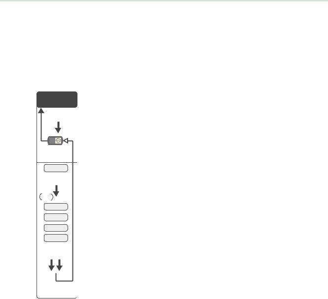
3.7.1 SITE (Site Survey) Menu
The SITE menu displays the results of a Site Survey conducted with this Gateway.
Gateway |
The SITE menu displays the device number of the Node the Site Survey was |
*SiteSITESurvey |
conducted with as well as the missed, green, yellow, and red received packet |
count. |
 Single-click
Button 2
Button 2
Double-click
adjust right rotary switch to survey the selected Node
NOD XX
Single-click
Button 2
AUTO
DISPLAY
 LOOP
LOOP
M XX
R XX
Y XX
G XX
Double-click
Button 2
The SITE menu is only available on the Gateways.
To access the SITE menu, single-click button 1 to scroll across the menu levels until reaching the Site Survey (SITE) menu.
See Conducting a Site Survey Using the Menu System on page 17.
See Interpreting the Site Survey Results on page 18.
Conducting a Site Survey Using the Menu System
Initiate a Site Survey using the Gateway’s buttons and menu system.
1.Remove the rotary dial access cover.
2.To check the status of Node 1, change the Gateway’s right rotary dial to 1.
The Gateway is now enabled to read the status of Node 1; the display scrolls through the Node’s I/O status.
3.Single-click button 1 to scroll across the menu levels until reaching the Site Survey (SITE) menu.
4.Single-click button 2 to enter the Site Survey menu.
5.Single-click button 2 to begin conducting a Site Survey with the Node selected in step 2.
The Gateway analyzes the quality of the signal from the selected Node by counting the number of data packets it receives from the Node.
6.Examine reception readings (M, R, Y, G) of the Gateway at various locations.
Site survey results display as a percentage. M represents the percent of missed packets while R, Y, and G represent the percent of received packets at a given signal strength.
M = Percent of missed packets; R = RED marginal signal; Y = YELLOW good signal; G = GREEN excellent signal. Record the results if you need troubleshooting assistance from the factory.
17

SureCross Wireless I/O Networks
7.Change the Gateway's right rotary dial to conduct a Site Survey with another Node and repeat steps 2 through 6.
8.To end the Site Survey, double-click button 2.
9.Change the Gateway's right rotary dial back to 0.
The LCD displays the device readings for the Gateway.
10.Double-click button 2 to move back to the top level menu.
11.Single-click button 1 to return to RUN mode.
12.Install the rotary dial access cover, referring to the Installation section of the manual to create an IP67 seal.
3.7.2 Interpreting the Site Survey Results
Site Survey results are listed as a percentage of data packets received and indicate the signal strength of the received signal.
|
Result |
Description |
|
Green |
Packets received at a strong signal strength. A strong signal strength is |
|
|
greater than −90 dBm at the receiver. |
|
Yellow |
Packets received at a good signal strength. A good signal is between |
|
|
−90 and −100 dBm at the receiver. |
|
Red |
Packets received at a weak signal strength. A weak signal is less than |
|
|
−100 dBm at the receiver. |
|
Missed |
Packets not received on the first transmission and requiring a retry. |
Judging if the reliability of a network’s signal meets the needs of the application is not just a matter of green, yellow, and red packets received. In normal operating mode, when data packets are not received, the transmitter re-sends the packet until all data is received.
For slow monitoring applications such as a tank farm, where data is required in terms of seconds or minutes, receiving most of the data in the ‘red’ range, indicating a weak but reliable signal, transmits enough data for accurate monitoring. Nodes positioned near the outside range of the radio signal may have 90% of the data packets received in the red zone, again indicating a weak, but reliable signal.
We recommend keeping the missed packets average to less than 40%. When the network misses more than 40% of the data packets, the signal is usually too unreliable or obstacles may be interfering with the signal. When Site Survey reports the missed packets are 40% or higher, improve the radio system performance by:
•Mounting the network’s antennas higher,
•Using higher gain antennas, or
•Adding data radios to the network.
Mounting the devices’ antennas higher allows the radio signal to clear obstacles in the area and improves the line of sight between SureCross® devices. Higher gain antennas focus the energy of the radio signal in a specific direction and extend the signal’s range. Using data radios is another option to consider when trying to extend the range of a radio network. For more information on data radios, please refer to Banner’s white paper on range extension on www.bannerengineering.com/surecross.
18

SureCross Wireless I/O Networks
3.7.3 Site Survey Troubleshooting
Some tips and tricks about improving radio signal reception may improve the site survey results.
Problem |
Solution |
|
|
Marginal Site Survey (RSSI) |
If the distance between devices is greater than about 5,000 meters (3 miles) line-of- |
Results |
sight *OR* objects, such as trees or man-made obstructions, interfere with the path, |
|
and the MISSED packet count exceeds 40 per 100 packets, consider the following |
|
steps: |
|
• Raise the DX80 units to a higher elevation, either by physically moving the |
|
devices or installing the antenna(s) remotely at a higher position. |
|
• Use high-gain antenna(s) such as Yagi and/or Omni (see Accessories). |
|
• Decrease the distance between devices. |
|
• Use data radios to extend the position of the Gateway relative to the host |
|
system. |
|
|
3.7.4 Conduct a Site Survey Using Modbus Commands
Use Modbus commands sent from the host system to start a Site Survey.
To start a Site Survey using a Modbus write holding register command, send a control code of 32 (0x20) and the Node number 1 through 15 (0x01 to 0x0F) to the Gateway Modbus holding register for I/O 15.
|
|
|
|
Modbus Register |
|
|
|
|
|
|
|
|
|
|
|
|
[15:8] |
|
|
[7:0] |
|
|
|
|
|
|
|
I/O 15 |
|
|
Control Code |
|
Data Field |
|
|
|
|
|
|
|
|
|
|
|
|
|
|
|
|
|
|
I/O 15 Control Messages |
|
||
|
|
|
|
|
||
Control Code |
Data Field |
Restrictions |
Description |
|
||
|
|
|
|
|||
32 |
Node # 1-15 |
Gateway only |
Enable Site Survey between Gateway and Node defined by the data |
|||
|
|
|
|
field. All error messages from the Gateway are ignored when running |
||
|
|
|
|
Site Survey. |
|
|
|
|
|
|
Only one Node can participate in Site Survey at a time. To disable |
||
|
|
|
|
the Site Survey, use control code 0x20 with Node 0. A Node must be |
||
|
|
|
|
enabled to run the Site Survey, then disabled before selecting the |
||
|
|
|
|
next Node. |
|
|
|
|
|
|
|
|
|
3.7.4 Example Command
Modbus Register
I/O 15 |
32 |
02 |
|
|
|
When Site Survey runs, the accumulated results are stored in the Gateway’s I/O 7 and I/O 8 holding registers. The LEDs on the both the Gateway and the Node’s front panel display the signal strength for the wireless RF link. The quality of the communications link is indicated by:
LED 1 is green = excellent signal strength
LED 2 is yellow/amber = good signal strength
LED 1 is red = poor signal strength
The signal strength is the transmitted signal strength relative to the ambient RF signal present in a specific location, or noise floor.
19
SureCross Wireless I/O Networks
The Gateway device also displays the Site Survey results on the LCD. For one transmit and receive interval, the Gateway saves the lowest signal strength. The LCD and Modbus registers contain the results of the last 100 samples. The totals are a running tally of the last 100 samples and are continuously updated. Four categories are displayed:
G (green) = excellent signal strength
Y (yellow) = good signal strength
R (red) = poor signal strength
M = Missed packet
To disable Site Survey, send a control code of 32 (0x20) and a Node number of 0 (0x0).
3.7.4 Site Survey Data Holding
With Site Survey active, registers I/O 7 and 8 are Site Survey data holding registers that store the accumulated Site Survey results. Error collections in holding register 8 are saved when Site Survey runs and restored after Site Survey is disabled.
|
|
Register |
||
|
|
|
|
|
|
[15:8] |
|
[7:0] |
|
|
|
|
|
|
I/O 7 |
Red Total |
|
|
Missed Total |
|
|
|
|
|
I/O 8 |
Green Total |
|
|
Yellow Total |
|
|
|
|
|
|
|
|
|
|
|
|
Example Results |
||
|
|
|
|
|
|
[15:8] |
|
[7:0] |
|
|
|
|
|
|
I/O 7 |
10 |
|
0 |
|
|
|
|
|
|
I/O 8 |
80 |
|
|
10 |
|
|
|
|
|
Note: This is the current register arrangement when using Modbus/TCP or Modbus RTU. In some older models, the Modbus/TCP registers are reversed (missed and yellow totals are in [8:15], red and green totals are in [0:7]).
20
SureCross Wireless I/O Networks
4 Installing Your SureCross® Radios
The following are some recommendations for installing your wireless network components.
4.1 Mounting SureCross Devices Outdoors
Use a Secondary Enclosure. For most outdoor applications, we recommend installing your SureCross devices inside a secondary enclosure. For a list of available enclosures, refer to the Accessories list.
Point Away From Direct Sunlight. When you are not using a secondary enclosure, minimize the damaging effects of ultra-violet radiation by mounting the devices to avoid facing intense direct sunlight.
• Mount under an overhang or other source of shade,
•Install indoors, or
•Face the devices north when installing outside.
For harsh outdoor applications, consider installing your radio inside a secondary enclosure. For a list of available enclosures, refer to the Accessories list.
Mount Vertically to Avoid Collecting Rain. When possible, mount the devices where rain or snow will drain away from the device.
•Mount vertically so that precipitation, dust, and dirt do not accumulate on permeable surfaces.
•Avoid mounting the devices on flat or concave surfaces, especially if the display will be pointing up.
Remove Moisture and Condensation. If condensation is present in any device, add a small desiccant packet to the inside of the radio. To help vent the radios, Banner also sells a vented plug (model number BWA-HW-031) for the 1/2-inch NPT port of the SureCross radios.
4.1.1 Watertight Glands and NPT Ports
4.1.1 Watertight Glands and Plugs
To make glands and plugs watertight, use PTFE tape and follow these steps.
1.Wrap four to eight passes of polytetrafluoroethylene (PTFE) tape around the threads as close as possible to the hexagonal body of the gland.
2.Manually thread the gland into the housing hole. Never apply more than 5 in-lbf of torque to the gland or its cable clamp nut. 2
Seal any unused PG-7 access holes with one of the supplied black plastic plugs. To install a watertight PG-7 plug:
1.Wrap four to eight passes of PTFE tape around the plug’s threads, as close as possible to the flanged surface.
2.Carefully thread the plastic plug into the vacant hole in the housing and tighten using a slotting screwdriver. Never apply more than 10 in-lbf torque to the plastic plug.
4.1.1 Watertight NPT Plugs
Seal the 1/2-inch NPT port if it is not used. To install a watertight NPT plug:
1. Wrap 12 to 16 passes of PTFE tape evenly across the length of the threads.
2This is not a lot of torque and is equivalent to the torque generated without using tools. If a wrench is used, apply only very light pressure. Torquing these fittings excessively damages the device.
21

SureCross Wireless I/O Networks
2.Manually thread the plug into the housing port until reaching some resistance.
3.Using a 9/16-inch crescent wrench, turn the plug until all the plug’s threads are engaged by the housing port or until the resistance doubles. Do not over-tighten as this will damage the SureCross unit. These threads are tapered and will create a waterproof seal without over-tightening.
4.2Other Installation Requirements
4.2Reduce Chemical Exposure
Before installing any devices in a chemically harsh environment, contact the manufacturer for more information regarding the life-expectancy. Solvents, oxidizing agents, and other chemicals will damage the devices.
4.2 Minimize Mechanical Stress
Although these radio devices are very durable, they are sophisticated electronic devices that are sensitive to shock and excessive loading.
•Avoid mounting the devices to an object that may be shifting or vibrating excessively. High levels of static force or acceleration may damage the housing or electronic components.
•Do not subject the devices to external loads. Do not step on them or use them as handgrips.
•Do not allow long lengths of cable to hang from the glands on the Gateway or Node. Cabling heavier than 100 grams should be supported instead of allowed to hang from the housing.
It is the user’s responsibility to install these devices so they will not be subject to overvoltage transients. Always ground the devices in accordance with local, state, or national regulations.
4.3 Installation Quick Tips
The following are some quick tips for improving the installation of wireless network components.
4.3.1 Create a Clear Communication Path
Wireless communication is hindered by radio interference and obstructions in the path between the transmitter and receiver. To achieve the best radio performance, carefully consider the installation locations for the Gateways and Nodes and select locations without obstructions in the path.
For more information about antennas, please refer to the Antenna Basics reference guide, Banner document p/n 132113.
4.3.2 Increase the Height of the Antennas
Position the external antenna vertically for optimal RF communication. If necessary, consider changing the height of the SureCross radio, or its antenna, to improve reception. For outdoor applications, mounting the antenna on top of a building or pole may help achieve a line-of-sight radio link with the other radios in the network.
Line of sight
Node
Gateway |
No line of sight |
|
22

SureCross Wireless I/O Networks
4.3.3 Collocated Radios
When the radio network’s master device is located too close to another radio device, communications between all devices is interrupted. For this reason, always assign a unique Network ID to your wireless networks. The Network ID (NID) is a unique identifier you assign to each wireless network to minimizes the chances of two collocated networks interfering with each other. Assigning different NIDs to different networks improves collocation performance in dense installations.
4.3.4 Be Aware of Seasonal Changes
When conducting the initial Site Survey, the fewest possible missed packets for a given link is better. However, seasonal changes may affect the signal strength and the total signal quality. Radios installed outside with 50% missed packets in the winter months may have 80% or more missed packets in the summer when leaves and trees interfere with radio reception.
Figure 1. A good signal in winter doesn't always mean you will get the same signal strength the rest of the year.
Figure 2. During spring and summer, leaves may block more of the radio signal.
4.4 Basic Remote Antenna Installation
A remote antenna system is any antenna system where the antenna is not connected directly to the radio; coaxial cable connects the antenna to the radio.
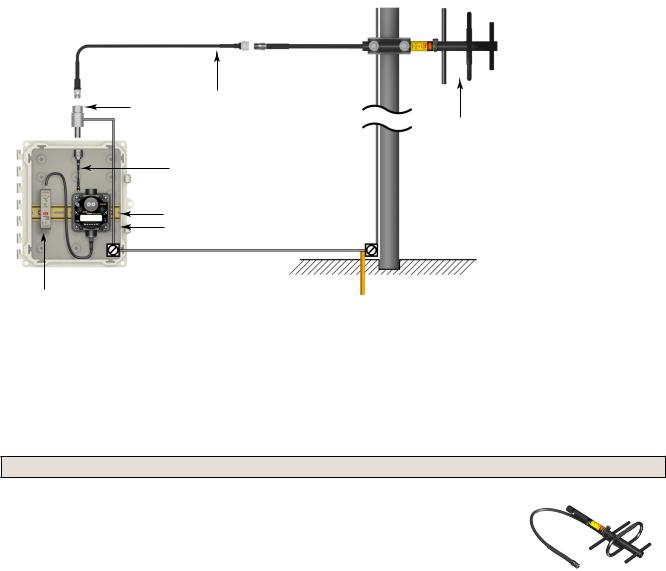
When installing a remote antenna system, always include a lightning arrestor or coaxial surge suppressor in the system. Remote antenna systems installed without surge protection invalidate the warranty of the radio devices.
Surge suppressors should be properly grounded and mounted at ground level near where the cabling enters a building. Install the surge suppressor indoors or inside a weatherproof enclosure to minimize corrosion or component deterioration. For best results, mount the surge suppressor as close to the ground as possible to minimize the length of the ground connection and use a single-point ground system to avoid creating ground loops.
For more detailed information about how antennas work and how to install them, refer to Antenna Basics (p/n 132113) (also included as a chapter within the product manual).
23
SureCross Wireless I/O Networks
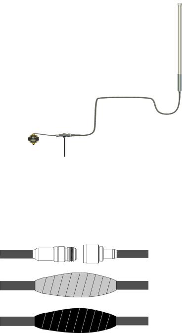
|
1. |
Antenna mounted remotely from |
|
|
the radio device. |
|
2. |
Coaxial cable |
1 |
3. |
Surge suppressor |
|
4. |
Ground wire to a single-point |
|
|
ground system |
2
3
4
I/O Isolation. When connecting analog and discrete I/O to external equipment such as VFDs (Variable Frequency Drives), it may be appropriate to install interposing relays and/or loop isolation devices to protect the DX80 unit from transients, noise, and ground plane interference originating from devices or the environment. Contact Banner Engineering Corp. for more information.
4.4.1 Weatherproof Remote Antenna Installations
Seal the connections with rubber splicing tape and electrical tape to prevent water damage to the cable and connections.
Step 1: Verify both connections are clean and dry before connecting the antenna cable to the antenna or other cable. Hand-tighten the cable connections.
Step 2: Tightly wrap the entire connection with rubber splicing tape. Begin wrapping the rubber splicing tape one inch away from the connection and continue wrapping until you are one inch past the other end of the connection. Each new round of tape should overlap about half the previous round.
Step 3: Protect the rubber splicing tape from UV damage by tightly wrapping electrical tape on top of the rubber splicing tape. The electrical tape should completely cover the rubber splicing tape and overlap the rubber tape by one inch on each side of the connection.
4.4.2 Antenna Installation
Antenna Installations. Install and properly ground a qualified surge suppressor when installing a remote antenna system. Remote antenna configurations installed without surge suppressors invalidate the manufacturer's warranty. Keep the ground wire as short as possible and make all ground connections to a single-point ground system to ensure no ground loops are created. No surge suppressor can absorb all lightning strikes; do not touch the SureCross® device or any equipment connected to the SureCross device during a thunderstorm.
24
SureCross Wireless I/O Networks
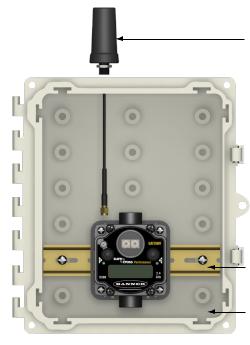
4.4.3 Mount a Dome Antenna to the Enclosure
Use a -D dome antenna when mounting an antenna directly to the outside of the enclosure.
1. Dome antenna
2. DIN rail and DIN rail bracket
3. Enclosure
The -D dome antennas come with an 18-inch RP-SMA 1 extension cable connected to the antenna. Use this
extension cable to connect the antenna directly to the radio.
To mount, drill a hole in the enclosure and insert the antenna.
2
3
Models |
Description |
List Price |
|
|
|
|
|
BWA-9O2-D |
Antenna, Omni, 900 MHz, 2 dBd, Dome, RP-SMA MALE Box mount, 18-inch |
$95 |
|
antenna cable |
|||
|
|
||
|
|
|
|
BWA-2O2-D |
Antenna, Omni, 2.4 GHz, 2 dBd, Dome, RP-SMA MALE Box mount, 18-inch |
$95 |
|
antenna cable |
|||
|
|
||
|
|
|
25
SureCross Wireless I/O Networks
4.4.4 Use an N-Type, Pole-Mounted Antenna
This antenna mounts remotely from the box, with the SureCross device mounted inside the box.
Ground the surge suppressor and antenna. Keep the ground wire as short as possible and make all ground connections to a single-point ground system to ensure no ground loops are created.
3 |
2 |
|
1
4
5, 6 8, 9
7
1.N-type Yagi antenna
2.N-Type to N-Type antenna cable
3.Surge suppressor
4.RP-SMA to N-Type male antenna cable
5and 6. DIN rail and DIN rail bracket
7.Power supply
8and 9. Enclosure and enclosure cover/plate, etc
Directional (Yagi) Antennas with an N-Type Female Connection
|
Models |
Frequency |
Description |
List Price |
|
|
|
BWA-9Y6-A |
|
6.5 dBd, 6.8 × 13 inches Outdoor |
$135 |
|
|
|
|
900 MHz |
|
|
|
|
|
BWA-9Y10-A |
10 dBd, 6.8 × 24 inches Outdoor |
$150 |
|
|
|
|
|
|
|
|||
|
|
|
|
|
|
|
26
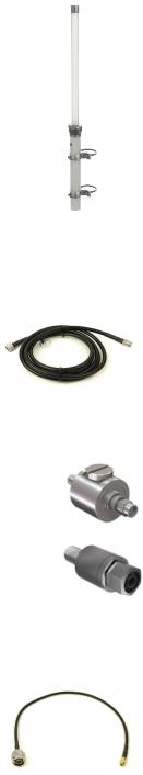
|
|
|
SureCross Wireless I/O Networks |
|
|
|
|
|
|
|
Omni-Directional Fiberglass Antennas with N-Type Female Connections |
|||
|
|
|
|
|
Models |
Frequency |
Description |
List Price |
|
|
|
|
|
|
BWA-9O6-A |
900 MHz |
6 dBd, Fiberglass, 71.5 inches |
$355 |
|
|
|
|
|
|
BWA-2O8-A |
2.4 GHz |
8.5 dBi, Fiberglass, 24 inches |
$200 |
|
|
|
|
|
|
BWA-2O6-A |
6 dBi, Fiberglass, 16 inches (shown) |
$125 |
|
|
|
|
|||
|
|
|
|
|
BWA-9O6-AS |
|
6 dBi, Fiberglass, 23.6 inches (1.3 inch dia.) |
$120 |
|
|
900 MHz |
|
|
|
BWA-9O8-AS |
8 dBi, Fiberglass, 63 inches (1.5 inch dia.) |
$215 |
|
|
|
|
|||
|
|
|
|
|
Use the LMR400 cables to connect the surge suppressor to the antenna.
Models |
Description |
List Price |
|
|
|
|
|
BWC-4MNFN3 |
LMR400 N-Type Male to N-Type Female, 3 m |
$77 |
|
|
|
|
|
BWC-4MNFN6 |
LMR400 N-Type Male to N-Type Female, 6 m |
$92 |
|
|
|
|
|
BWC-4MNFN15 |
LMR400 N-Type Male to N-Type Female, 15 m |
$156 |
|
|
|
|
|
BWC-4MNFN30 |
LMR400 N-Type Male to N-Type Female, 30 m |
$296 |
|
|
|
|
|
Model |
Description |
Connection |
List Price |
|
|
|
|
|
|
BWC-LMRSFRPB |
Surge Suppressor, Bulkhead, RP-SMA |
RP-SMA to RP-SMA |
$111 |
|
Type |
|
|||
|
|
|
|
|
|
|
|
|
|
BWC-LFNBMN-DC |
Surge Suppressor, bulkhead, N-Type, |
N-Type Female, N-Type |
$120 |
|
dc Blocking |
Male |
|
||
|
|
|
||
|
|
|
|
|
Use the RP-SMA to N-Type male cables to connect the radio to the surge suppressor.
Model |
Description |
List Price |
|
|
|
|
|
BWC-1MRSMN05 |
LMR100 RP-SMA to N-Type Male, 0.5 m |
$40 |
|
|
|
|
|
27

SureCross Wireless I/O Networks
5 Advanced Setup Instructions and Additional
Information
Refer to the following sections for advanced setup instructions or additional information on Banner's SureCross wireless technology and its uses.
5.1 DX80 Menu Structure
The Gateways and Nodes each have their own menu structure and options.
5.1 DX80 Gateway Set-up Menu
When power is applied, the DX80 begins running. The display screen auto loops through the RUN menu and communication begins between the Gateway and Node(s). Auto looping through the RUN menu is the normal operating mode for all devices on the wireless network.
From the RUN Menu (or any menu), single-click button 1 to advance through the top-level menus. The device auto display loops through the menu options if either of the RUN, DINFO, or FCTRY menus are selected. If the device is paused on the SITE, DVCFG, or DERR menu options, the display does not auto loop.
To enter manual scrolling mode, double-click button 2 at the top level menu. Use the instructions shown in the chart below to navigate the menu system. To return to the top level menus and auto display loop mode, double-click button 2 twice.
The * before the menu name indicates a top-level menu option. The () indicate submenu items.
When using Rotary Dial Addressing Mode, use the left rotary dial to set the Network ID (NID). Once changed, allow five seconds for the devices to update to the new Network ID.
Single-click Button 1 to advance through
RUN |
DINFO |
FCTRY |
||
* |
|
* Device Info |
* Factory Info |
|
AUTO |
adjust the rotary |
AUTO |
AUTO |
|
DISPLAY |
switches to survey |
DISPLAY |
DISPLAY |
|
LOOP |
the selected Node |
LOOP |
LOOP |
|
|
|
|
||
Single-click |
Single-click |
Single-click |
Single-click |
|
Button 1 |
Button 1 |
|||
Button 1 |
Button 1 |
|
|
|
NID XX |
NID XX |
(DEV) |
(DEV) |
|
GATEWY |
GATEWY |
|||
|
|
|||
(DEV) |
(DEV) |
(NAME) |
|
|
|
|
(RADIO |
||
GATEWY |
GATEWY |
|
||
XXXXXX |
|
|||
|
|
MICRO) |
||
I/O XX |
I/O XX |
|
||
XXXXXX |
V 00.0 A |
|||
|
|
|||
|
|
|
||
ON/OFF |
ON/OFF |
XXXXXX |
|
|
(NID) |
(LCD |
|
|
||
XX |
MICRO) |
|
|
||
|
V 00.0 A |
|
(SLID) |
|
|
XX |
(DX80 |
|
|
||
(BAUD) |
S/N) |
|
(0000) |
||
XX |
||
|
||
(PRTY) |
(DX80 |
|
|
||
XX |
MODEL) |
|
|
||
|
(0000-00) |
|
|
(PROD |
|
|
DATE) |
|
|
(00-00) |
*SiteSITESurvey
 Single-click Button 2
Button 2
Double-click
adjust right rotary switch to survey the selected Node
NOD XX
Single-click
Button 2
AUTO
DISPLAY
 LOOP
LOOP
M XX
R XX
Y XX
G XX
Double-click
Button 2
DVCFG |
|
DERR |
|
|
|
|
*Device Config |
*Device Error |
*ERROR |
New Error |
|
||
Single-click |
Single-click |
Detected |
|
|||
Button 2 |
|
Button 2 |
Single-click |
|
|
|
|
|
|
|
Button 2 |
|
|
|
|
NOD XX |
Single-click Button 1 to advance through menu |
|||
|
|
|
|
|
||
|
|
EC XX |
CLEAR |
DISABL |
IGNORE |
|
2 |
|
|
|
Single-click |
Single-click |
Single-click |
Button |
|
|
|
Button 2 |
Button 2 |
Button 2 |
|
|
|
ERR |
ERR |
|
|
click- |
|
|
|
ERASED |
DISABL |
|
|
|
|
|
|
||
Double |
|
Next |
|
Single-click |
Single-click |
|
|
Device |
|
Button 2 |
Button 2 |
|
|
|
|
|
|
|||
|
|
|
|
|
|
|
Single-click Button 1 to advance through menu
|
(NID) |
|
||||
|
Network ID |
|
|
|||
|
Single-click |
|
|
|||
Double-click Button 2 |
Button 2 |
|
|
|||
|
|
|
switches |
|||
|
|
|
||||
|
|
|
||||
|
|
|
||||
|
to set the network ID |
|||||
|
CUR XX |
|
|
|||
|
NEW XX |
|
|
|||
|
Single-click |
|
|
|||
|
Button 2 |
|
|
|||
|
|
|
|
|
Double-click |
Button 2 |
|
SAVES NEW |
|||||
VALUES
(SLID) |
(BAUD) |
(PRTY) |
(MAXN) |
Slave ID |
Baud Rate |
Parity |
Timing |
Single-click |
Single-click |
Single-click |
Single-click |
Button 2 |
Button 2 |
Button 2 |
Button 2 |
|
click-SingleB1 |
9600 |
click-SingleB1 |
None |
|
8 |
adjust rotary switches |
38400 |
Odd |
B1click-Single |
32 |
||
to set slave ID, using |
|
19200 |
|
Even |
|
16 |
button 1 to select the |
|
|
|
|
|
|
digits |
|
|
|
|
|
|
CUR XX |
Single-click |
Single-click |
|
48 |
||||
|
|
|
||||||
NEW XX |
Button 2 |
Button 2 |
|
Single-click |
||||
Single-click |
|
|
|
|
|
Button 2 |
||
|
|
|
|
|||||
Button 2 |
SAVES |
SAVES |
|
|
|
|||
|
|
DISPLAYED |
DISPLAYED |
|
|
|
||
|
|
VALUE |
VALUE |
|
SAVES |
|||
SAVES NEW |
|
|
|
|
|
DISPLAYED |
||
|
|
|
|
|
VALUE |
|||
VALUES |
|
|
|
|
|
|
|
|
* Set to 000000 to use the serial number.
|
|
(XADR) |
|||||
|
|
Extended Addressing |
|||||
|
|
Single-click |
|
|
|||
|
|
Button 2 |
|
|
|||
|
|
|
|
|
|
Single-click |
|
|
B1 |
AUTO |
|
||||
|
|
Button 2 |
|
||||
|
-click |
|
|
|
|
NETWRK |
|
|
Single |
MANUAL |
|||||
|
BINDNG |
||||||
|
|
||||||
|
|
Single-click |
|||||
|
|
Single-click |
|||||
|
|
Button 2 |
|||||
|
|
|
|
|
|
Button 1 or 2 |
|
|
|
|
|
|
|
|
|
|
|
SET |
|
|
|||
|
|
Reboot |
|||||
|
|
XADR |
|||||
|
|
|
|
||||
|
|
|
|
|
|
|
|
|
B1 |
ADJUST ROTARY |
|
|
|||
|
-click |
|
|
||||
|
SWITCH TO |
|
|
||||
|
Single |
SET XADR |
|
|
|||
XXXXXX *
Single-click
Button 2
CONFRM
XADR
XXXXX
Single-click
Button 2
SAVED
28
SureCross Wireless I/O Networks
5.1 DX80 Node Set-up Menu
When power is applied, the DX80 begins running. The display screen auto loops through the RUN menu and communication begins between the Gateway and Node(s). Auto looping through the RUN menu is the normal operating mode for all devices on the wireless network.
From the RUN Menu (or any menu), single-click button 1 to advance through the top-level menus. The device auto display loops through the menu options if either of the RUN, DINFO, or FCTRY menus are selected. If the device is paused on the DVCFG or DERR menu options, the display does not auto display loop.
To enter manual scrolling mode, double-click button 2 at the top level menu. Use the instructions shown in the chart below to navigate the menu system. To return to the top level menus and auto display loop mode, double-click button 2 twice.
Node LCD Timeout: After 15 minutes of inactivity, the LCD screen stops displaying information. Press any button to refresh the display if the Node has entered this energy-saving mode.
The * before the menu name indicates a top-level menu option. The () indicate submenu items.
When using Rotary Dial Addressing Mode, use the rotary dials to set the Network ID (NID) and Device ID (NADR) at any time. The left rotary dial sets the Network ID and the right rotary dial sets the Node Address. Once changed, allow five seconds for the devices to update to the new Network ID.
29
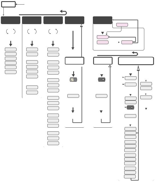
SureCross Wireless I/O Networks
OFF |
Press and hold Button 1 from any top level menu to power down the Node. |
|
Press and hold Button 1 from power down mode to enter RUN mode. |
||
|
||
|
Single-click Button 1 to advance through menu |
RUN |
DINFO |
FCTRY |
|
* |
* Device Info |
* |
Factory #s |
AUTO |
AUTO |
|
AUTO |
DISPLAY |
DISPLAY |
|
DISPLAY |
LOOP |
LOOP |
|
LOOP |
Single-click |
Single-click |
|
Single-click |
Button 1 |
Button 1 |
|
Button 1 |
NID XX |
(DEV) |
|
(DEV) |
(DEV) |
NOD XX |
|
NOD XX |
NOD XX |
|
|
|
I/O XX |
(NAME) |
|
(RADIO |
0.00 |
NODE XX |
|
MICRO) |
ON/OFF |
KIT |
|
V 00.0 A |
XXXXX
(LCD
MICRO)
(NID)
0x0000(2)
XX
(DX80
S/N)
0x0000(2)
(DX80
MODEL)
0x0000(2)
(PROD
DATE)
(00-00)
*DVCFG
Device Config.
Single-click
Button 2
Double-click Btn 2
(NID)
Network ID
Single-click
Button 2
ADJUST LEFT
ROTARY SWITCH
TO SET
NETWORK ID
NEW XX
Single-click
Button 2
SAVES NEW
VALUES
DERR |
|
|
|
|
|
*Device Error |
*ERROR |
New Error |
|
||
Single-click |
Detected |
|
|||
Button 2 |
Single-click |
|
2 |
||
|
|
Button 2 |
Single-click Button 1 |
Button |
|
|
|
||||
|
|
|
|||
NOD XX |
|
-click |
|||
|
|
|
|||
** EC XX |
Single-click |
IGNORE |
Single |
||
Button 2 |
|
||||
** LCD will display ‘NO ERR’ if no error is detected.
Single-click Button 1 to advance through menu
(NADR) |
|
|
|
|
(XADR) |
|||||||||
Node Address |
|
|
|
|
Extended Addressing |
|||||||||
Single-click |
|
|
|
Single-click |
|
|
|
|||||||
Button 2 |
|
|
|
|
Button 2 |
|
|
|
||||||
|
|
|
|
B1 |
|
|
|
|
|
|
|
Single-click |
|
|
|
|
|
|
|
|
|
|
|
|
|
||||
|
|
|
|
-click |
|
|
|
AUTO |
Button 2 |
|
||||
|
|
|
|
|
|
|
|
|
|
|
|
|||
|
|
|
|
|
|
|
|
|
|
|
|
|
|
|
ADJUST RIGHT |
Single |
|
|
|
MANUAL |
|
NETWRK |
|||||||
ROTARY SWITCH |
|
|
|
|
||||||||||
|
TO SET |
|
|
|
|
Single-click |
|
BINDNG |
||||||
NODE ADDRESS |
|
|
|
|
|
|||||||||
NEW XX |
|
|
|
|
Button 2 |
|
|
|
||||||
|
|
|
|
|
|
|
||||||||
|
|
|
|
|
|
|
|
|
|
|
||||
|
|
|
|
SET |
|
BOUND |
||||||||
|
|
|
|
|
|
|
|
|
||||||
|
|
|
|
|
|
|
|
|
|
|
||||
Single-click |
|
|
|
|
XADR |
|
Single-click |
|||||||
|
|
|
|
|
Button 1 or 2 |
|||||||||
Button 2 |
clickB1 |
|
|
|
|
|
|
|
|
|
|
|||
|
|
|
|
|
|
|
|
|
|
|
|
|
|
|
|
|
|
|
|
Adjust rotary switch |
|
Reboot |
|||||||
|
|
|
|
|
||||||||||
|
|
|
|
Single |
|
|
|
to set XADR |
|
|||||
SAVES NEW |
|
|
|
XXXXXX |
|
|
|
|||||||
VALUES |
|
|
|
|
|
|
|
|||||||
|
|
|
|
Single-click |
|
|
|
|||||||
|
|
|
|
|
|
|
|
|
|
|
||||
|
|
|
|
|
|
|
|
Button 2 |
|
|
|
|||
|
|
|
|
|
|
|
|
|
|
|
|
-Doubleclick |
Button2 |
|
|
|
|
|
|
|
|
|
|
|
|
|
|||
CONFRM
XADR
XXXXX
PRIOR
NADR
XX
NEW
NADR
XX
CONFRM
NADR
XX
30
Loading...