


 Loading...
PIKE II 3108 Series
PIKE II 3108-8i
PIKE II 3108-4i4e

E13674
Revised Edition V3
December 2017
Copyright © 2017 ASUSTeK COMPUTER INC. All Rights Reserved.
No part of this manual, including the products and software described in it, may be reproduced, transmitted, transcribed, stored in a retrieval system, or translated into any language in any form or by any means, except documentation kept by the purchaser for backup purposes, without the express written permission of ASUSTeK COMPUTER INC. (“ASUS”).
Product warranty or service will not be extended if: (1) the product is repaired, modified or altered, unless such repair, modification of alteration is authorized in writing by ASUS; or (2) the serial number of the product is defaced or missing.
ASUS PROVIDES THIS MANUAL “AS IS” WITHOUT WARRANTY OF ANY KIND, EITHER EXPRESS OR IMPLIED, INCLUDING BUT NOT LIMITED TO THE IMPLIED WARRANTIES OR CONDITIONS OF MERCHANTABILITY OR FITNESS FOR A PARTICULAR PURPOSE. IN NO EVENT SHALL ASUS, ITS DIRECTORS, OFFICERS, EMPLOYEES OR AGENTS BE LIABLE FOR ANY INDIRECT, SPECIAL, INCIDENTAL, OR CONSEQUENTIAL DAMAGES (INCLUDING DAMAGES FOR LOSS OF PROFITS, LOSS OF BUSINESS, LOSS OF USE OR DATA, INTERRUPTION OF BUSINESS AND THE LIKE), EVEN IF ASUS HAS BEEN ADVISED OF THE POSSIBILITY OF SUCH DAMAGES ARISING FROM ANY DEFECT OR ERROR IN THIS MANUAL OR PRODUCT.
SPECIFICATIONS AND INFORMATION CONTAINED IN THIS MANUAL ARE FURNISHED FOR INFORMATIONAL USE ONLY, AND ARE SUBJECT TO CHANGE AT ANY TIME WITHOUT NOTICE, AND SHOULD NOT BE CONSTRUED AS A COMMITMENT BY ASUS. ASUS ASSUMES NO RESPONSIBILITY OR LIABILITY FOR ANY ERRORS OR INACCURACIES THAT MAY APPEAR IN THIS MANUAL, INCLUDING THE PRODUCTS AND SOFTWARE DESCRIBED IN IT.
Products and corporate names appearing in this manual may or may not be registered trademarks or copyrights of their respective companies, and are used only for identification or explanation and to the owners’ benefit, without intent to infringe.
ii

Contents
Contents...................................................................................................................... |
iii |
About this guide........................................................................................................... |
v |
PIKE II 3108 Series specifications summary........................................................... |
vii |
Chapter 1: Product Introduction
1.1 |
Welcome! |
..................................................................................................... |
1-2 |
1.2 |
Package contents....................................................................................... |
1-2 |
|
1.3 |
Card layout.................................................................................................. |
1-3 |
|
|
1.3.1 |
Switch settings............................................................................. |
1-4 |
1.4 |
System requirements................................................................................. |
1-5 |
|
1.5 |
Card installation.......................................................................................... |
1-6 |
|
Chapter 2: RAID Configuration
2.1 |
Setting up RAID.......................................................................................... |
2-2 |
|
|
2.1.1 |
RAID definitions........................................................................... |
2-2 |
|
2.1.2 |
Installing hard disk drives............................................................ |
2-3 |
2.2 |
MegaRAID Configuration Utility................................................................ |
2-3 |
|
|
2.2.1 |
Starting the MegaRAID Configuration Utility................................ |
2-4 |
|
2.2.2 |
MegaRAID Configuration Utility................................................... |
2-5 |
|
2.2.3 |
VD Mgmt Menu............................................................................ |
2-7 |
|
2.2.4 |
PD Mgmt Menu............................................................................ |
2-8 |
|
2.2.5 |
Ctrl Mgmt Menu........................................................................... |
2-9 |
|
2.2.6 |
Properties Menu........................................................................ |
2-10 |
|
2.2.7 |
Foreign View Menu.................................................................... |
2-11 |
|
2.2.8 |
Managing Software Licensing.................................................... |
2-12 |
|
2.2.9 |
Creating a Storage Configuration.............................................. |
2-13 |
|
2.2.10 |
Selecting Additional Virtual Drive Properties............................. |
2-14 |
|
2.2.11 |
Modifying Controller Properties................................................. |
2-17 |
|
2.2.12 |
Viewing and Changing Virtual Drive Properties......................... |
2-20 |
|
2.2.13 |
Deleting a Virtual Drive.............................................................. |
2-20 |
|
2.2.14 |
Deleting a Virtual Drive Group................................................... |
2-21 |
|
2.2.15 |
Initializing a Virtual Drive........................................................... |
2-21 |
|
2.2.16 |
Running a Consistency Check................................................... |
2-22 |
iii

2.3 |
MegaRAID Storage Manager.................................................................... |
2-23 |
|
|
2.3.1 |
Hardware and Software Requirements...................................... |
2-23 |
|
2.3.2 |
Installing MegaRAID Storage Manager Software on |
|
|
|
Microsoft Windows OS.............................................................. |
2-23 |
|
2.3.3 |
Installing MegaRAID Storage Manager Software for Linux....... |
2-27 |
|
2.3.4 |
Linux Error Messages................................................................ |
2-28 |
|
2.3.5 |
Starting the MegaRAID Storage Manager Software.................. |
2-29 |
|
2.3.6 |
MegaRAID Storage Manager Window....................................... |
2-31 |
Chapter 3: Driver Installation
3.1 |
RAID driver installation.............................................................................. |
3-2 |
|
|
3.1.1 |
Windows® Server 2012 R2 OS.................................................... |
3-2 |
|
3.1.2 |
Red Hat® Enterprise Linux OS 7.0............................................... |
3-4 |
|
3.1.3 |
SUSE Linux OS 12...................................................................... |
3-6 |
Simplified EU Declaration of Conformity................................................................ |
3-8 |
||
ASUS contact information....................................................................................... |
3-9 |
||
iv

About this guide
This user guide contains the information you need when installing and configuring the server management board.
How this guide is organized
This guide contains the following parts:
•Chapter 1: Product Introduction
This chapter offers the PIKE II 3108 SAS RAID card features and the new technologies it supports.
•Chapter 2: RAID Configuration
This chapter provides instructions on setting up, creating, and configuring RAID sets using the available utilities.
•Chapter 3: Driver Installation
This chapter provides instructions for installing the RAID drivers on different operating systems.
Where to find more information
Refer to the following sources for additional information and for product and software updates.
1.ASUS websites
The ASUS website provides updated information on ASUS hardware and software products. Refer to the ASUS contact information.
2.Optional documentation
Your product package may include optional documentation, such as warranty flyers, that may have been added by your dealer. These documents are not part of the standard package.
v

Conventions used in this guide
To make sure that you perform certain tasks properly, take note of the following symbols used throughout this manual.
DANGER/WARNING: Information to prevent injury to yourself when trying to complete a task.
CAUTION: Information to prevent damage to the components when trying to complete a task.
IMPORTANT: Instructions that you MUST follow to complete a |
|
task. |
|
NOTE: Tips and additional information to help you complete a |
|
task. |
|
Typography |
|
Bold text |
Indicates a menu or an item to select. |
Italics |
Used to emphasize a word or a phrase. |
<Key> |
Keys enclosed in the less-than and greater-than sign means |
|
that you must press the enclosed key. |
|
Example: <Enter> means that you must press the Enter or |
|
Return key. |
<Key1+Key2+Key3> |
If you must press two or more keys simultaneously, the key |
|
names are linked with a plus sign (+). |
|
Example: <Ctrl+Alt+Del> |
Command |
Means that you must type the command exactly as shown, |
|
then supply the required item or value enclosed in |
|
brackets. |
Example: At the DOS prompt, type the command line: format a:
vi
PIKE II 3108 Series specifications summary
|
PIKE II 3108-8i/16PD |
PIKE II 3108-8i/240PD |
PIKE II |
|
3108-4i4e/240PD |
||
|
|
|
|
|
|
|
|
Controller |
LSI SAS 3108 |
|
|
|
|
|
|
Interface |
PCI-E Gen 3 |
|
|
|
|
|
|
|
8 SAS 12Gb/s Ports (2 Mini-SAS HD SFF-8643) |
8 SAS 12Gb/s Ports |
|
Ports |
|
|
(1 Mini-SAS HD SFF- |
|
|
8643 + 1 Mini-SAS |
|
|
|
|
|
|
|
|
HD SFF-8644) |
|
|
|
|
Support Device |
SAS / SAS II /SAS 12Gb/s devices |
|
|
SATA II / SATA III devices |
|
|
|
|
|
|
|
|
|
|
|
Data transfer rate |
SAS 12Gb/s |
|
|
|
|
|
|
RAID Support |
RAID 0/1/10/5/50/6/60 |
|
|
|
|
|
|
Max. PHD |
Max. physical Disk qty |
Max. physical Disk qty for RAID: 240 |
|
for RAID: 16 |
|
|
|
|
|
|
|
|
|
|
|
Cache |
1GB on board SDRAM |
|
|
|
|
|
|
Battery Backup |
Header reserved for LSI CacheVault |
|
|
Support |
(acquired from LSI existing distribution channel) |
|
|
|
|
|
|
Form factor |
Standard low profile |
|
|
|
|
|
|
Only supports ASUS Z10,Z9,P9 motherboards/systems.
*The exact OS support would base on the OS support list of the motherboard.
**Specifications are subject to change without notice.
vii

viii
Product Introduction |
1 |
This chapter offers the PIKE II 3108 SAS RAID card features and the new technologies it supports.

1.1Welcome!
Thank you for buying an ASUS® PIKE II 3108 Series SAS RAID card!
The ASUS PIKE II 3108 Series SAS RAID card supports 12 Gb/s SAS Technology and allows you to create RAID 0, RAID 1, RAID 10, RAID 5, RAID 50, RAID 6, and RAID 60 sets from SATA II/SATA III/SAS/SAS II/SAS III hard disk drives connected to the SAS connectors on the card.
Before you start installing the RAID card, check the items in your package with the list below.
1.2Package contents
Check your package for the following items:
•ASUS PIKE II 3108 Series SAS RAID card
•Support DVD
If any of the above items is damaged or missing, contact your retailer.
1-2 |
Chapter 1: Product Introduction |

1.3Card layout
The illustration below shows the major components of the RAID card.
PIKE II 3108-8i
DEFAULT_SEL1

 HBLED1

 DRLED1

 FAILLED1
PIKE II 3108-4i4e
DEFAULT_SEL1

 HBLED1

 DRLED1

 FAILLED1
1.PCI-E x8 interface
2.Internal mini-SAS HD connectors
3.External mini-SAS HD connector
4.Switch* (for more than one card)
5.HBLED1 (HEARTBEAT LED): The LED shows the firmware heartbeat information
(blinking)
6.DRLED1 (Dirty cache LED): Write Pending (light)
7.FAILLED1 (Global Drive Fault LED): Drive fault detected (light)
8.CacheVault connector
ASUS PIKE II 3108 Series |
1-3 |
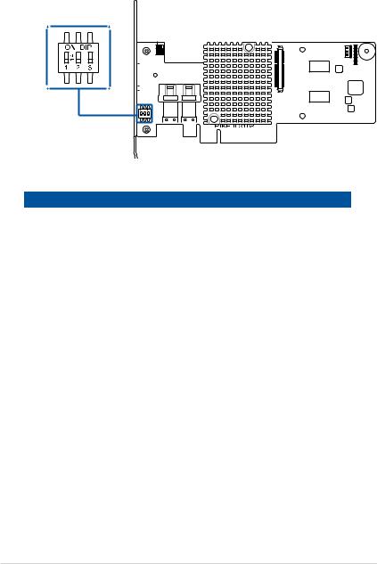
1.3.1Switch settings
When using more than one PIKE II card on your system, ensure to manually set the pin settings on the Switch on each of the PIKE II cards to ensure that the system detects all the cards installed. You can refer to the following table for the pin settings.
DEFAULT_SEL1

 HBLED1

 DRLED1

 FAILLED1
PIKE II card Switch pin settings and recommended configuration:
PIKE 3108 |
Switch |
Pin name |
Pin value |
|
|
|
|
1 |
SW1 |
[1:2:3] |
111 |
2 |
SW1 |
[1:2:3] |
110 |
3 |
SW1 |
[1:2:3] |
101 |
4 |
SW1 |
[1:2:3] |
100 |
5 |
SW1 |
[1:2:3] |
011 |
6 |
SW1 |
[1:2:3] |
010 |
7 |
SW1 |
[1:2:3] |
001 |
8 |
SW1 |
[1:2:3] |
000 |
1-4 |
Chapter 1: Product Introduction |

1.4System requirements
Before you install the PIKE II 3108 Series RAID card, check if the system meets the following requirements:
•ASUS Server motherboard
•PCI-E Gen3 slot
•SAS or SATA hard disk drives
•Mini-SAS HD cable
•Supported operating system:
-Windows® and Linux operating systems (refer to website for details)
•Other requirements:
-Appropriate thermal solution
-Certified power supply module
Ensure to update your BIOS to the latest version before using PIKE II 3108 series on ASUS Z9 or P9 series platform.
ASUS PIKE II 3108 Series |
1-5 |
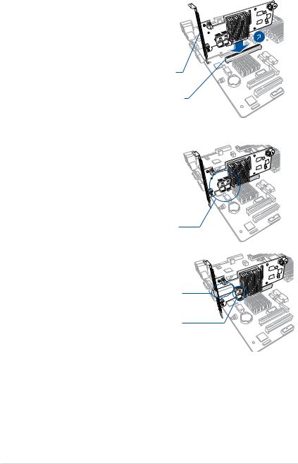
1.5Card installation
To install the RAID card on your motherboard:
1.Locate the PCIE Gen3 slot on the
motherboard.
2. Align the golden fingers of the PIKE card with the PCIE Gen3 card slot.
3. Insert the RAID card into the PCIE Gen3 card slot. Ensure the card is completely seated in place.
PIKE RAID card
PCI-E slot
4.For PIKE II 3108-8i, connect the hard
disk drives to the internal Mini-SAS HD connectors.
For PIKE II 3108-4i4e, connect the hard disk drives to the internal and external Mini-SAS HD connectors.
Internal mini-SAS HD connector
External mini-SAS HD connector |
Internal mini-SAS HD connector |
1-6 |
Chapter 1: Product Introduction |
RAID Configuration
This chapter provides instructions on setting up, creating, and |
2 |
configuring RAID sets using the available utilities. |

2.1Setting up RAID
The RAID card supports RAID 0, 1, 10, 5, 50, 6, and 60.
2.1.1RAID definitions
RAID 0 (Data striping) optimizes two identical hard disk drives to read and write data in parallel, interleaved stacks. Two hard disks perform the same work as a single drive but at a sustained data transfer rate, double that of a single disk alone, thus improving data access and storage. Use of at least two new identical hard disk drives is required for this setup.
RAID 1 (Data mirroring) copies and maintains an identical image of data from one drive to a second drive. If one drive fails, the disk array management software directs all applications to the surviving drive as it contains a complete copy of the data in the other drive. This RAID configuration provides data protection and increases fault tolerance to the entire system. Use two new drives or use an existing drive and a new drive for this setup. The new drive must be of the same size or larger than the existing drive.
RAID 10 is a striped configuration with RAID 1 segments whose segments are RAID 1 arrays. This configuration has the same fault tolerance as RAID 1, and has the same overhead for fault-tolerance as mirroring alone. RAID 10 achieves high input/output rates by striping RAID 1 segments. In some instances, a RAID 10 configuration can sustain multiple simultaneous drive failure. A minimum of four hard disk drives is required for this setup.
RAID 5 stripes both data and parity information across three or more hard disk drives. Among the advantages of RAID 5 configuration include better HDD performance, fault tolerance, and higher storage capacity. The RAID 5 configuration is best suited for transaction processing, relational database
applications, enterprise resource planning, and other business systems. Use a minimum of three identical hard disk drives for this setup.
RAID 50 is a combination of RAID 0 and RAID 5. It uses distributed parity and disk striping and works best with data that requires high reliability, high request rates, high data transfers, and medium-to-large capacity.
RAID 6 uses distributed parity, with two independent parity blocks per stripe, and disk striping. A RAID 6 virtual drive can survive the loss of two drives without losing data. A RAID 6 drive group, which requires a minimum of three drives, is similar to a RAID 5 drive group. Blocks of data and parity information are written across all drives. The parity information is used to recover the data if one or two drives fail in the drive group.
RAID 60, a combination of RAID 0 and RAID 6, uses distributed parity, with two independent parity blocks per stripe in each RAID set, and disk striping. A RAID 60 virtual drive can survive the loss of two drives in each of the RAID 6 sets without losing data. It works best with data that requires high reliability, high request rates, high data transfers, and medium-to-large capacity.
2-2 |
Chapter 2: RAID Configuration |

•Having RAID 0 and RAID 5 virtual disks in the same physical array is
not recommended. If a drive in the physical array has to be rebuilt, the RAID 0 virtual disk will cause a failure during the rebuild.
•If you want to boot the system from a hard disk drive included in a created RAID set, copy first the RAID driver from the support CD to a floppy disk before you install an operating system to the selected hard disk drive.
2.1.2Installing hard disk drives
The RAID card supports SAS for RAID set configuration. For optimal performance, install identical drives of the same model and capacity when creating a disk array.
To install SAS hard disks for RAID configuration:
1.Install the SAS hard disks into the drive bays following the instructions in the system user guide.
2.Connect a SAS signal cable to the signal connector at the back of each drive and to the SAS connector on the motherboard.
3.Connect a power cable to the power connector on each drive.
2.2MegaRAID Configuration Utility
The AVAGO MegaRAID SAS-MFI BIOS Utility is an integrated RAID solution that allows you to create RAID 0, 1, 10, 5, 50, 6, and 60 sets from SATA II/SATA III/ SAS/SAS II/SAS III hard disk drives supported by the LSI SAS 3108 12Gb/s SAS controller.
•Create drive groups and virtual drives for storage configurations
•Delete virtual drives
•Migrate a storage configuration to a different RAID level
•Detect configuration mismatches
•Import a foreign configuration
•Display controller, virtual drive, physical drive, and change parameters.
•Scan devices connected to the controller
•Initialize virtual drives
•Check configurations for data consistency
•Create a CacheCade™ configuration
•You may use disks of different sizes; however, the size of the smallest disk
determines the “logical” size of each member disk.
•DO NOT combine Serial ATA and SAS disk drives in one volume.
•The RAID setup screens shown in this section are for reference only and may not exactly match the items on your screen due to the controller version difference.
ASUS PIKE II 3108 Series |
2-3 |

2.2.1Starting the MegaRAID Configuration Utility
Follow these steps to start the MegaRAID Configuration Utility and access the main screen.
1.Turn on the system after installing all SAS hard disk drives.
2.During POST, press <Ctrl+R> when the following screen appears
3.If the system has multiple SAS controllers, a controller selection dialog appears. Select a controller and press <Enter>.
2-4 |
Chapter 2: RAID Configuration |
Loading...