


PIKE 2008/IMR
LSISAS RAID card
User Guide

E5905
First Edition V1
November 2010
Copyright © 2010 ASUSTeK COMPUTER INC. All Rights Reserved.
No part of this manual, including the products and software described in it, may be reproduced, transmitted, transcribed, stored in a retrieval system, or translated into any language in any form or by any means, except documentation kept by the purchaser for backup purposes, without the express written permission of ASUSTeK COMPUTER INC. (“ASUS”).
Product warranty or service will not be extended if: (1) the product is repaired, modified or altered, unless such repair, modification of alteration is authorized in writing byASUS; or (2) the serial number of the product is defaced or missing.
ASUS PROVIDES THIS MANUAL “AS IS” WITHOUT WARRANTY OF ANY KIND, EITHER EXPRESS OR IMPLIED, INCLUDING BUT NOT LIMITED TO THE IMPLIED WARRANTIES OR CONDITIONS OF MERCHANTABILITY OR FITNESS FOR A PARTICULAR PURPOSE. IN NO EVENT SHALL ASUS, ITS DIRECTORS, OFFICERS, EMPLOYEES OR AGENTS BE LIABLE FOR ANY INDIRECT, SPECIAL, INCIDENTAL, OR CONSEQUENTIAL DAMAGES (INCLUDING DAMAGES FOR LOSS OF PROFITS, LOSS OF BUSINESS, LOSS OF USE OR DATA, INTERRUPTION OF BUSINESS AND THE LIKE), EVEN IF ASUS HAS BEEN ADVISED OF THE POSSIBILITY OF SUCH DAMAGES ARISING FROM ANY DEFECT OR ERROR IN THIS MANUAL OR PRODUCT.
SPECIFICATIONS AND INFORMATION CONTAINED IN THIS MANUAL ARE FURNISHED FOR INFORMATIONAL USE ONLY, AND ARE SUBJECT TO CHANGE AT ANY TIME WITHOUT NOTICE, AND SHOULD NOT BE CONSTRUED AS A COMMITMENT BY ASUS. ASUS ASSUMES NO RESPONSIBILITY OR LIABILITY FOR ANY ERRORS OR INACCURACIES THAT MAY APPEAR IN THIS MANUAL, INCLUDING THE PRODUCTS AND SOFTWARE DESCRIBED IN IT.
Products and corporate names appearing in this manual may or may not be registered trademarks or copyrights of their respective companies, and are used only for identification or explanation and to the owners’ benefit, without intent to infringe.
ii

Contents
Contents....................................................................................................... |
iii |
About this guide.......................................................................................... |
iv |
PIKE 2008/IMR specifications summary................................................... |
vi |
Chapter 1: |
Product introductio n |
|
|
1.1 |
Welcome! |
....................................................................................... |
1-2 |
1.2 |
Package contents......................................................................... |
1-2 |
|
1.3 |
Card layout.................................................................................... |
1-3 |
|
1.4 |
System requirements................................................................... |
1-3 |
|
1.5 |
Card installation............................................................................ |
1-4 |
|
Chapter 2: |
RAID configuration |
|
|
2.1 |
Setting up RAID............................................................................ |
2-2 |
|
|
2.1.1 |
RAID definitions............................................................... |
2-2 |
|
2.1.2 |
Installing hard disk drives................................................ |
2-3 |
2.2 |
LSI WebBIOS Configuration Utility............................................. |
2-4 |
|
|
2.2.1 |
Starting the WebBIOS CU............................................... |
2-5 |
|
2.2.2 |
WebBIOS CU main screen options................................. |
2-6 |
|
2.2.3 |
Creating a Storage Configuration.................................... |
2-8 |
|
2.2.4 |
Viewing and Changing Device Properties..................... |
2-22 |
|
2.2.5 |
Viewing System Event Information................................ |
2-29 |
|
2.2.6 |
Managing Configurations............................................... |
2-30 |
2.3 |
MegaRAID Storage Manager...................................................... |
2-34 |
|
|
2.3.1 |
Hardware and Software Requirements......................... |
2-34 |
|
2.3.2 |
Installing MegaRAID Storage Manager Software on |
2-34 |
|
|
Microsoft Windows OS.................................................. |
|
|
2.3.3 |
Installing MegaRAID Storage Manager Software for |
2-38 |
|
|
Linux.............................................................................. |
|
|
2.3.4 |
Linux Error Messages.................................................... |
2-39 |
|
2.3.5 |
Starting MegaRAID Storage Manager Software............ |
2-40 |
|
2.3.6 |
MegaRAID Storage Manager Window.......................... |
2-42 |
Chapter 3: |
Driver installation |
|
|
3.1 |
RAID driver installation................................................................ |
3-2 |
|
|
3.1.1 |
Creating a RAID driver disk............................................. |
3-2 |
|
3.1.2 |
Windows® Server 2003 OS.............................................. |
3-4 |
|
3.1.3 |
Red Hat® Enterprise Linux OS 5...................................... |
3-9 |
|
3.1.4 |
SUSE Linux OS 11......................................................... |
3-11 |
iii

About this guide
This user guide contains the information you need when installing and configuring the server management board.
How this guide is organized
This guide contains the following parts:
•Chapter 1: Product introduction
This chapter offers the PIKE 2008/IMR SAS RAID card features and the new technologies it supports.
•Chapter 2: RAID configuration
This chapter provides instructions on setting up, creating, and configuring
RAID sets using the available utilities.
•Chapter 3: Driver installation
This chapter provides instructions for installing the RAID drivers on different operating systems.
Where to find more information
Refer to the following sources for additional information and for product and software updates.
1.ASUS websites
The ASUS website provides updated information on ASUS hardware and software products. Refer to the ASUS contact information.
2.Optional documentation
Your product package may include optional documentation, such as warranty flyers, that may have been added by your dealer. These documents are not part of the standard package.
iv

Conventions used in this guide
To make sure that you perform certain tasks properly, take note of the following symbols used throughout this manual.
DANGER/WARNING: Information to prevent injury to yourself when trying to complete a task.
CAUTION: Information to prevent damage to the components when trying to complete a task.
IMPORTANT: Instructions that you MUST follow to complete a task.
NOTE: Tips and additional information to help you complete a task.
Typography
Bold text |
Indicates a menu or an item to select. |
Italics |
Used to emphasize a word or a phrase. |
<Key> |
Keys enclosed in the less-than and greater-than sign means |
|
that you must press the enclosed key. |
|
Example: <Enter> means that you must press the Enter or |
|
Return key. |
<Key1+Key2+Key3> |
If you must press two or more keys simultaneously, the key |
|
names are linked with a plus sign (+). |
|
Example: <Ctrl+Alt+Del> |
Command |
Means that you must type the command exactly as shown, |
|
then supply the required item or value enclosed in |
|
brackets. |
|
Example: At the DOS prompt, type the command line: |
|
format a: |
PIKE 2008/IMR specifications summary
Controller
Interface
Ports
Support device
Data transfer rate
RAID level
OS support*
Form factor
LSISAS2008
ASUS PIKE interface
8 ports
SAS/SAS II devices
SATA/SATA II/SATA III devices
SATA III and SAS II 6Gb/s per PHY
RAID 0/RAID 1/RAID 10/RAID 5/RAID 50
Windows® XP Professional SP3
Windows® Server 2003 SP2 Enterprise Edition Windows® Server 2003 SP2 Standard Edition Windows® Server 2008 Enterprise Edition SP2 Windows® Server 2008 Enterprise Edition R2 Windows® Server 2008 Standard Edition SP2 Windows® Server 2008 Standard Edition R2 Windows® 7 (Ultimate)
Red Hat Enterprise Linux AS 4.8
Red Hat Enterprise Linux AS 5.5
SuSE Linux Enterprise Server 10.3
SuSE Linux Enterprise Server 11.1
Fedora 12
Free BSD 8.1
Cent OS 5.5
ESX4.0 UP1
ESXi4.0
6.44 in x 1.57 in (1U compatible)
* The exact OS support would base on the OS support list of the motherboard. ** Specifications are subject to change without notice.
vi
This chapter offers the PIKE 2008/IMR SAS |
1 |
RAID card features and the new technologies |
|
it supports. |
|
Chapter 1: |
Product |
introduction

1.1Welcome!
Thank you for buying an ASUS® PIKE 2008/IMR SAS RAID card!
The ASUS PIKE 2008/IMR allows you to create RAID 0, RAID 1, RAID 10, RAID 5, and RAID 50 sets from SATA/SATA II/SATA III/SAS/SAS II hard disk drives connected to the SAS connectors on the motherboard.
Before you start installing the RAID card, check the items in your package with the list below.
1.2Package contents
Check your package for the following items.
•ASUS PIKE 2008/IMR SAS RAID card
•Support CD
•User guide
If any of the above items is damaged or missing, contact your retailer.
1-2 |
Chapter 1: Product introduction |
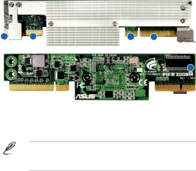
1.3Card layout
The illustration below shows the major components of the RAID card.
2 |
2 |
1 |
1 |
3
1.ASUS PIKE interface-1: PCI-E x8
2.ASUS PIKE interface-2: 8-port SAS signal with SGPIO interface*
3.SAS RAID card status LED (lights up and blinks to indicate that the card is working normally)
*The SGPIO interface is used for visibility into drive activity, failure and rebuild status, so that users could build high-performatnce and reliable storage systems. Refer to the motherboard manual for detailed information about using the SGPIO connectors on the motherboard.
1.4System requirements
Before you install the PIKE 2008/IMR SAS RAID card, check if the system meets the following requirements:
•Workstation or server motherboard with a PIKE RAID card slot
•SAS or SATA hard disk drives
•Supporting operating system:
Windows® and Linux operating systems (refer to website for details)
•Other requirement:
-Appropriate thermal solution
-Certified power supply module
ASUS PIKE 2008/IMR |
1-3 |
1.5Card installation
Follow the below instructions to install the RAID card on your motherboard.
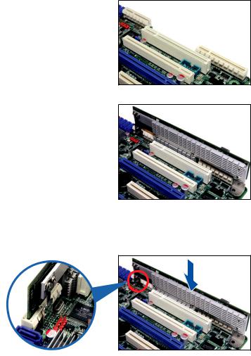
For 2U, 5U, or pedestal server
To install ASUS PIKE 2008/IMR SAS RAID card on a 2U, 5U, or pedestal server
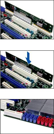
1.Locate the PIKE RAID card slot on the motherboard.
2.Align the golden fingers of the RAID card with the PIKE RAID card slot.
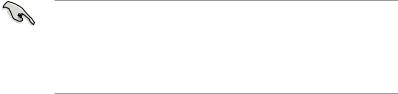
3.Insert the RAID card into the PIKE RAID card slot. Ensure the card is completely inserted into the card slot, and the heatsink latch is completely hooked to the edge of the card slot.
1-4 |
Chapter 1: Product introduction |

4.Secure the heatsink to the nearest screw hole on the motherboard.
DO NOT overtighten the screw, or the motherboard component can be damaged.
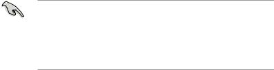
5.Connect the hard disk drives to the SAS connectors on the motherboard.
To uninstall ASUS PIKE 2008/IMR SAS RAID card from a 2U, 5U, or pedestal server
1.Disconnect all SAS hard disk drives from the motherboard.
2.Remove the screw that secures the RAID card to the motherboard.
3.Release the heatsink latch from the card slot with a finger, and then remove the RAID card from the slot.
ASUS PIKE 2008/IMR |
1-5 |
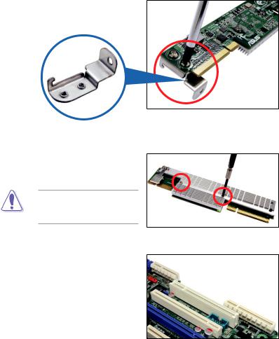
For 1U server
You have to remove the outer heatsink of ASUS PIKE 2008/IMR SAS RAID card to install the card in a 1U server.
To install ASUS PIKE 2008/IMR SAS RAID card on a 1U server
1.Remove the two screws that secure the heatsink bracket on the back of the SAS RAID card.
Heatsink bracket
2.Remove the two screws that secure the outer heatsink on the front of the SAS RAID card.
DO NOT remove the inner heatsink from the SAS RAID card.
3.Locate the PIKE RAID card slot on the motherboard.
1-6 |
Chapter 1: Product introduction |
4.Align the golden fingers of the
RAID card with the PIKE RAID card slot.
5.Insert the RAID card into the PIKE RAID card slot. Ensure the card is completely inserted into the card slot.
6.Connect the hard disk drives to the SAS connectors on the motherboard.
ASUS PIKE 2008/IMR |
1-7 |

1-8 |
Chapter 1: Product introduction |
This chapter provides instructions on setting |
2 |
up, creating, and configuring RAID sets using |
|
the available utilities.Chapter 2: RAID
configuration
2.1Setting up RAID
The RAID card supports RAID 0, RAID 1, RAID 10, RAID 5, and RAID 50.
2.1.1RAID definitions
RAID 0 (Data striping) optimizes two identical hard disk drives to read and write data in parallel, interleaved stacks. Two hard disks perform the same work as a single drive but at a sustained data transfer rate, double that of a single disk alone, thus improving data access and storage. Use of at least two new identical hard disk drives is required for this setup.
RAID 1 (Data mirroring) copies and maintains an identical image of data from one drive to a second drive. If one drive fails, the disk array management software directs all applications to the surviving drive as it contains a complete copy of
the data in the other drive. This RAID configuration provides data protection and increases fault tolerance to the entire system. Use two new drives or use an existing drive and a new drive for this setup. The new drive must be of the same size or larger than the existing drive.
RAID 10 is a striped configuration with RAID 1 segments whose segments are RAID 1 arrays. This configuration has the same fault tolerance as RAID 1, and has the same overhead for fault-tolerance as mirroring alone. RAID 10 achieves high input/output rates by striping RAID 1 segments. In some instances, a RAID
10 configuration can sustain multiple simultaneous drive failure.Aminimum of four hard disk drives is required for this setup.
RAID 5 stripes both data and parity information across three or more hard disk drives.Among the advantages of RAID 5 configuration include better
HDD performance, fault tolerance, and higher storage capacity. The RAID
5 configuration is best suited for transaction processing, relational database applications, enterprise resource planning, and other business systems. Use a minimum of three identical hard disk drives for this setup.
RAID 50 is a combination of RAID 0 and RAID 5. It uses distributed parity and disk striping and works best with data that requires high reliability, high request rates, high data transfers, and medium-to-large capacity.
• Having RAID 0 and RAID 5 virtual disks in the same physical array is not
recommended. If a drive in the physical array has to be rebuilt, the RAID 0 virtual disk will cause a failure during the rebuild.
•If you want to boot the system from a hard disk drive included in a created
RAID set, copy first the RAID driver from the support CD to a floppy disk before you install an operating system to the selected hard disk drive.
2-2 |
Chapter 2: RAID configuration |
2.1.2Installing hard disk drives
The RAID card supports SAS for RAID set configuration. For optimal performance, install identical drives of the same model and capacity when creating a disk array.
To install SAS hard disks for RAID configuration:
1.Install the SAS hard disks into the drive bays following the instructions in the system user guide.
2.Connect a SAS signal cable to the signal connector at the back of each drive and to the SAS connector on the motherboard.
3.Connect a power cable to the power connector on each drive.
ASUS PIKE 2008/IMR |
2-3 |
2.2LSI WebBIOS Configuration Utility
The LSI WebBIOS Configuration Utility (CU) is an integrated RAID solution that allows you to create RAID 0, 1, 10, 5, and 50 sets from SATA/SATA II/SATA III/SAS/ SAS II hard disk drives supported by the LSI SAS 2008 controller.
You can also use the WebBIOS CU to do the following tasks:
•Create drive groups and virtual drives for storage configurations
•Delete virtual drives
•Detect configuration mismatches
•Import a foreign configuration
•Display controller, virtual drive, drive, and change parameters.
•Scan devices connected to the controller
•Initialize virtual drives
•Check configurations for data consistency
•Create a CacheCade™ configuration
•You may use disks of different sizes; however, the size of the smallest disk determines the “logical” size of each member disk.
•DO NOT combine Serial ATA and SAS disk drives in one volume.
•The RAID setup screens shown in this section are for reference only and may not exactly match the items on your screen due to the controller version difference.
2-4 |
Chapter 2: RAID configuration |

2.2.1Starting the WebBIOS CU
Follow these steps to start the WebBIOS CU and access the main screen.
1.Turn on the system after installing all SAS hard disk drives.
2.During POST, press <Ctrl+H> when the following screen appears
Press <Ctrl+Y> for Preboot CLI: this option is for advanced debug only!
LSI MegaRAID SAS-MFI |
BIOS |
|
|
|||
Version 4.15.00 |
(Build June 03, 2010) |
|
||||
Copyright(C) 2010 LSI Corporation |
|
|||||
HA -0 (Bus |
4 Dev 0) LSI MegaRAID ROMB |
|
||||
FW package: 20.7.1-0016 |
|
|
||||
Battery Status: Not present |
|
|
||||
|
PCI SLOT |
ID |
LUN |
VENDOR |
PRODUCT |
REVISION |
|
-------- |
-- |
--- |
------ |
------- |
-------- |
|
5 |
|
|
LSI |
LSI MegaRAID ROMB |
|
|
5 |
0 |
0 |
ATA |
Hitachi HDS72161 |
AB3A |
|
5 |
0 |
0 |
ATA |
Hitachi HDS72161 |
AB3A |
|
5 |
0 |
0 |
ATA |
Hitachi HDS72161 |
AB3A |
|
5 |
0 |
0 |
ATA |
Hitachi HDS72161 |
AB3A |
3 |
JBOD(s) found |
on the host adapter. |
|
|||
3 |
JBOD(s) handled by |
BIOS |
|
|
||
0 |
Virtual Drive(s) found on the host adapter. |
|
||||
0 |
Virtual Drive(s) handled by BIOS |
|
||||
Press <Ctrl><H> |
for WebBIOS or press <Ctrl><Y> for Preboot CLI |
|||||
|
|
|
|
|
|
|
3.The Adapter Selection screen appears. If the system has multiple SAS adapters, select an adapter.
4.Click Start to continue. The main WebBIOS CU screen appears.
ASUS PIKE 2008/IMR |
2-5 |
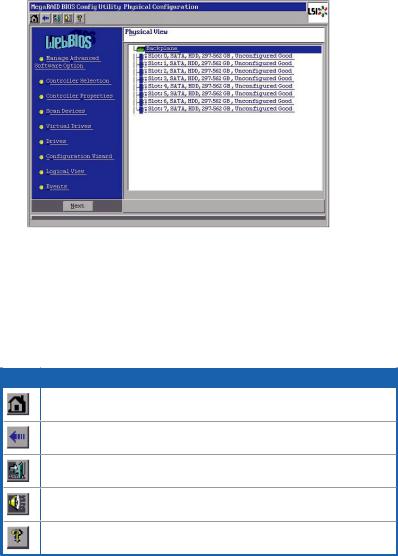
2.2.2WebBIOS CU main screen options
This is the Physical View screen which displays the drives that are connected to the controller. To toggle between the physical view and logical view of the storage devices connected to the controller, click Physical View or Logical View in the menu on the left. When the Logical View screen is displayed, you can see all the virtual drives that are configured on this controller.
WebBIOS CU Toolbar Icons
Icon Description
Click this icon to return to the main screen from any other WebBIOS CU screen.
Click this icon to return to the previous screen that you were viewing.
Click this icon to exit the WebBIOS CU program.
Click this icon to turn off the sound on the onboard controller alarm.
Click this icon to display information about the WebBIOS CU version, bus number, and device number.
2-6 |
Chapter 2: RAID configuration |
Here is a description of the options listed on the left of the main WebBIOS CU screen:
•ManageAdvanced Software Option: Select this to allow you to enable the special functionality or features that may not be available in the standard configuration of the controller.
•Controller Selection: Select this to view the Adapter Selection screen, where you can select a different SAS adapter. You can then view information about the controller and the devices connected to it, or create a new configuration on the controller.
•Controller Properties: Select this to view the properties of the currently selected SAS controller.
•Scan Devices: Select this to have the WebBIOS CU re-scan the physical and virtual drives for any changes in the drive status or the physical configuration.
The WebBIOS CU displays the results of the scan in the physical and virtual drive descriptions.
•Virtual Drives: Select this to view the Virtual Drives screen, where you can change and view virtual drive properties, initialize drives, and perform other tasks.
•Drives: Select this to view the Drives screen, where you can view drive properties, and perform other tasks.
•Configuration Wizard: Select this to start the Configuration Wizard and create a new storage configuration, clear a configuration, or add a configuration.
•Physical View/Logical View: Select this to toggle between the Physical View and Logical View screens.
•Events: Select this to view system events in the Event Information screen.
•Exit: Select this to exit the WebBIOS CU and continue with system boot.
ASUS PIKE 2008/IMR |
2-7 |
2.2.3Creating a Storage Configuration
This section explains how to use the WebBIOS CU Configuration Wizard to configure RAID arrays and virtual drives.
Selecting the Configuration with the Configuration Wizard
Follow these steps to start the Configuration Wizard, and select a configuration option and mode:
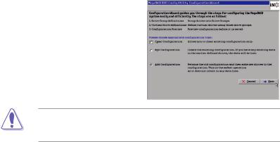
1.Click Configuration Wizard on the WebBIOS main screen. The first Configuration Wizard screen appears, as shown in the right figure.
2.Select a configuration option.
If you choose the first or second option, all existing data in the configuration will be deleted. Make a backup of any data that you want to keep before choosing these options.
•Clear Configuration: Clears the existing configuration.
•New Configuration: Clears the existing configuration and lets you create a new configuration.
•Add Configuration: Retains the existing storage configuration and adds new drives to it (this does not cause any data loss).
3.Click Next. A dialog box warns that you will lose data if you select Clear
Configuration or New Configuration.
4.On the next screen, select a configuration mode:
•Manual Configuration:Allows you to control all attributes of the new storage configuration.
•Automatic Configuration:Automatically creates an optimal RAID configuration.
If you select AutomaticConfiguration, you can choose the redundancy mode:
•Redundancy when possible:Automatically creates an optimal RAID configuration, providing data redundancy.
•No Redundancy:Automatically creates a non-redundant RAID 0 configuration.
5.Click Next to continue.
2-8 |
Chapter 2: RAID configuration |
 Loading...