


PI-P55TP4N

P/I-P55TP4N Motherboard
USER'S MANUAL

P/I-P55TP4N User's Manual
II
USER'S NOTICE
No part of this product, including the product and software may be repro-
duced, transmitted, transcribed, stored in a retrieval system, or translated
into any language in any form by any means without the
express written permission of ASUSTeK COMPUTER INC.(hereinafter
referred to as ASUS) except documentation kept by the purchaser for backup
purposes.
ASUS provides this manual "as is" without warranty of any kind, either
express or implied, including but not limited to the implied warranties or
conditions of merchantability or fitness for a particular purpose. In no
event shall ASUS be liable for any loss or profits, loss of business, loss of
use or data, interruption of business, or for indirect, special, incidental, or
consequential damages of any kind, even if ASUS has been advised of the
possibility of such damages arising from any defect or error in this manual
or product. ASUS may revise this manual from time to time without no-
tice. For updated BIOS, drivers, or product release information you may
visit ASUSTeK's home page at: http://www.asus.com.tw/
Products mentioned in this manual are mentioned for identification pur-
poses only. Product names appearing in this manual may or may not be
registered trademarks or copyrights of their respective companies.
The product name and revision number are both printed on the mother-
board itself. Manual revisions are released for each motherobard design
represented by the digit before the period and for additions or corrections
represented by the digit after the period. The BIOS version noted below
represents the current release during this manual release. Your BIOS ver-
sion displayed on the top-left of the screen during bootup may be newer,
especially if you download the BIOS file from a BBS or FTP server.
© Copyright 1996 ASUSTeK Computer Inc. All rights reserved.
Product Name: P/I-P55TP4N
Product Revision: 1.01
Manual Revision: 2.0
BIOS Version: #401A0-0201 or later
Release Date: May 1996

P/I-P55TP4N User's Manual
III

P/I-P55TP4N User's Manual
IV
CONTENTS
I. INTRODUCTION.........................................................1
How this manual is organized.......................................................... 1
Item Checklist .................................................................................. 1
II. FEATURES..................................................................2
Features of This Motherboard.......................................................... 2
Parts of the Motherboard ................................................................. 3
III. INSTALLATION ........................................................4
Map of the Motherboard .................................................................. 4
Jumpers................................................................................. 5
Expansion Slots .................................................................... 5
Connectors ............................................................................ 5
Installation Steps.............................................................................. 6
1. Jumpers ........................................................................................ 6
Jumper Settings .................................................................... 8
2. System Memory (DRAM) .......................................................... 12
DRAM Memory Installation Procedures: ............................ 13
Level 2 External Static RAM (SRAM) Cache ........................... 14
Compatible Cache Modules for this Motherboard ............... 14
3. Central Processing Unit (CPU)................................................... 15
4. Expansion Cards ......................................................................... 16
Expansion Card Installation Procedure: ............................... 16
Assigning IRQs for Expansion Cards................................... 16
Assigning DMA Channels for ISA Cards............................. 17
ASUS MediaBus Card.......................................................... 18
5. External Connectors.................................................................... 19
Final Power Connection Procedures .................................... 25

P/I-P55TP4N User's Manual
V
CONTENTS
IV. BIOS SOFTWARE .....................................................26
6. BIOS Setup ................................................................................. 26
Standard CMOS Setup ............................................................... 27
Details of Standard CMOS Setup:........................................ 28
BIOS Features Setup .................................................................. 31
Details of BIOS Features Setup:........................................... 31
Chipset Features Setup ............................................................... 34
Power Management Setup.......................................................... 37
Details of Power Management Setup: .................................. 37
PNP and PCI Setup .................................................................... 39
Load BIOS Defaults ................................................................... 41
Load Setup Defaults ................................................................... 41
Supervisor Password and User Password .................................. 42
IDE HDD Auto Detection .......................................................... 43
Save and Exit Setup ................................................................... 44
Exit Without Saving ................................................................... 44
Flash Memory Writer Utility ........................................................... 45
The Flash Memory Writer Utility Screen:............................ 47
Details of Advanced Features:.............................................. 48
V. DESKTOP MANAGEMENT......................................50
Desktop Management Interface (DMI)............................................ 50
Introducing the DMI utility .................................................. 50
System Requirements ........................................................... 50
Using the DMI utility ........................................................... 51
Notes:.................................................................................... 51
VI. PCI-SC200 SCSI Card...............................................55
NCR SCSI BIOS and Drivers .......................................................... 55
The PCI-SC200 SCSI Interface Card .............................................. 56
Setting Up the PCI-SC200 ......................................................... 56
Setting the INT Assignment ....................................................... 57
Terminator Settings .................................................................... 57
SCSI ID Numbers ...................................................................... 58

P/I-P55TP4N User's Manual
VI
FCC & DOC COMPLIANCE
Federal Communications Commission Statement
This device complies with FCC Rules Part 15. Operation is subject to the
following two conditions:
• This device may not cause harmful interference, and
• This device must accept any interference received, including inter-
ference that may cause undesired operation.
This equipment has been tested and found to comply with the limits for a
Class B digital device, pursuant to Part 15 of the FCC Rules. These limits
are designed to provide reasonable protection against harmful interference
in a residential installation. This equipment generates, uses and can radiate
radio frequency energy and, if not installed and used in accordance with
manufacturer's instructions, may cause harmful interference to radio com-
munications. However, there is no guarantee that interference will not oc-
cur in a particular installation. If this equipment does cause harmful inter-
ference to radio or television reception, which can be determined by turn-
ing the equipment off and on, the user is encouraged to try to correct the
interference by one or more of the following measures:
• Re-orient or relocate the receiving antenna.
• Increase the separation between the equipment and receiver.
• Connect the equipment to an outlet on a circuit different from that
to which the receiver is connected.
• Consult the dealer or an experienced radio/TV technician for help.
WARNING: The use of shielded cables for connection of the monitor to
the graphics card is required to assure compliance with FCC regulations.
Changes or modifications to this unit not expressly approved by the party
responsible for compliance could void the user's authority to operate this
equipment.
Canadian Department of Communications Statement
This digital apparatus does not exceed the Class B limits for
radio noise emissions from digital apparatus set out in the Radio Interfer-
ence Regulations of the Canadian Department of Communications.

P/I-P55TP4N User's Manual
1
I. INTRODUCTION
I. INTRODUCTION
(Manual / Checklist)
How this manual is organized
This manual is divided into the following sections:
I. Introduction: Manual information and checklist
II. Features: Information and specifications concerning this product
III. Installation: Instructions on setting up the motherboard.
IV. BIOS Setup: BIOS software setup information.
V. DMI Utility: BIOS supported Desktop Management Interface
VI. PCI-SC200: Installation of an optional SCSI card.
Item Checklist
Please check that your package is complete. If you discover damaged or
missing items, please contact your retailer.
√ The P/I-P55TP4N motherboard
√ 2 serial port ribbon cables attached to a mounting bracket
√ 1 parallel ribbon cable with mounting bracket
√ 1 IDE ribbon cable
√ 1 floppy ribbon cable
√ 1 diskette containing support software as follows:
• Flash Memory Writer utility to update the FLASH BIOS
• Binary file containing BIOS information
• Desktop Management Interface (DMI) software
• Readme files gives instructions on use of the files
√ This user's manual
Optional PS/2 mouse cable with mounting bracket
Optional infrared module
Optional ASUS pipelined burst cache module
Optional PCI-SC200 SCSI card

P/I-P55TP4N User's Manual
2
II. FEATURES
Features of This Motherboard
The P/I-P55TP4N is carefully designed for the demanding PC user who
wants a great many features in a small package. This motherboard:
• Easy Installation: Is equipped with BIOS supports auto detection of
hard drives and Plug and Play to make setup of hard drives and expan-
sion cards virtually automatic.
• Multi-Speed Support: Supports one 75-166MHz Pentium CPU on a
ZIF Socket 7.
• Intel Chipset: Features Intel's 430FX PCIset with I/O subsystems.
• Desktop Management Interface (DMI): Supports DMI through BIOS
which allows hardware to communicate within a standard protocol cre-
ating a higher level of compatibility.
• L2 Cache: Provides the option of 0KB upgradeable to 256KB or
512KB, or onboard 256KB Pipelined Burst SRAM upgradeable to
512KB. Upgrades are made through a Synchronous SRAM cache
module. (See page 14 for compatible cache modules.)
• V ersatile DRAM Memory Support: Supports 72-pin SIMMs of 4MB,
8MB, 16MB, or 32MB to form a memory size between 8MB to 128MB.
Supports both Fast Page Mode and Extended Data Output (EDO)
SIMMs.
• ISA and PCI Expansion Slots: Provides three 16-bit ISA slots, three
32-bit PCI slots, and one PCI/MediaBus 2.0 which allows the use of
either an standard PCI card or the ASUS MediaBus Card.
• ASUS MediaBus Rev 2.0: Features an expansion slot extension shared
with PCI Slot 4 for an optional high-performance expansion card which
includes two functions in one easy-to-install card. (For revision com-
patibility information, please refer to page 18.)
• Super Multi-I/O: Provides two high-speed UART compatible serial
ports and one parallel port with EPP and ECP capabilities. UART2
can also be directed to the Infrared Module for wireless connections.
T wo floppy drives of either 5.25" or 3.5" (1.44MB or 2.88MB) are also
supported without an external card. The Japanese "Floppy 3 mode"
(3.5" 1.2MB) floppy standard is also supported.
(Features)
II. FEATURES
P/I-P55TP4N User's Manual
3
II. FEATURES
• PCI Bus Master IDE Controller: Comes with an onboard PCI Bus
Master IDE controller with two connectors that supports four IDE de-
vices in two channels, provides faster data transfer rates, and supports
Enhanced IDE devices such as T ape Backup and CD-ROM drives. This
controller supports PIO Modes 3 and 4 and Bus Master IDE DMA
Mode 2. BIOS supports IDE CD-ROM boot-up.
• Optional IrDA and PS/2 Mouse Connector: This motherboard sup-
ports an optional infrared port module for wireless interface and a PS/
2 mouse cable set.
• NCR SCSI BIOS: This motherboard has firmware that supports the
optional ASUS PCI-SC200 SCSI controller cards.
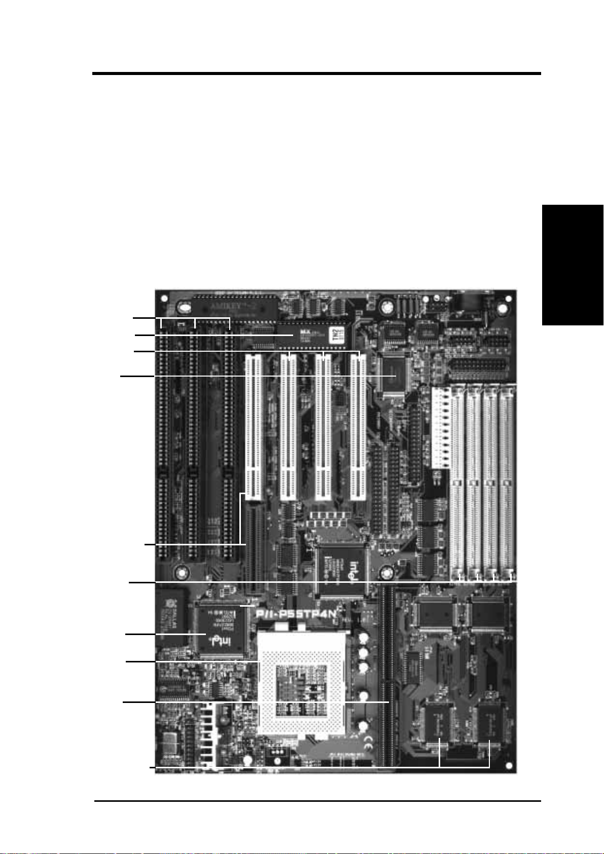
Parts of the Motherboard
II. FEATURES
(Parts of Board)
PCI 4 or ASUS
MediaBus 2.0
Intel's 430FX
PCIset
Onboard 256KB/
512KB Pipelined
Burst L2 Cache
CPU ZIF
Socket 7
3 PCI Slots
Super
Multi-I/O
Flash ROM
72-pin SIMM
Sockets
L2 Upgrade
Cache
Expansion Slot
3 ISA Slots
P/I-P55TP4N User's Manual
4
III. INSTALLATION
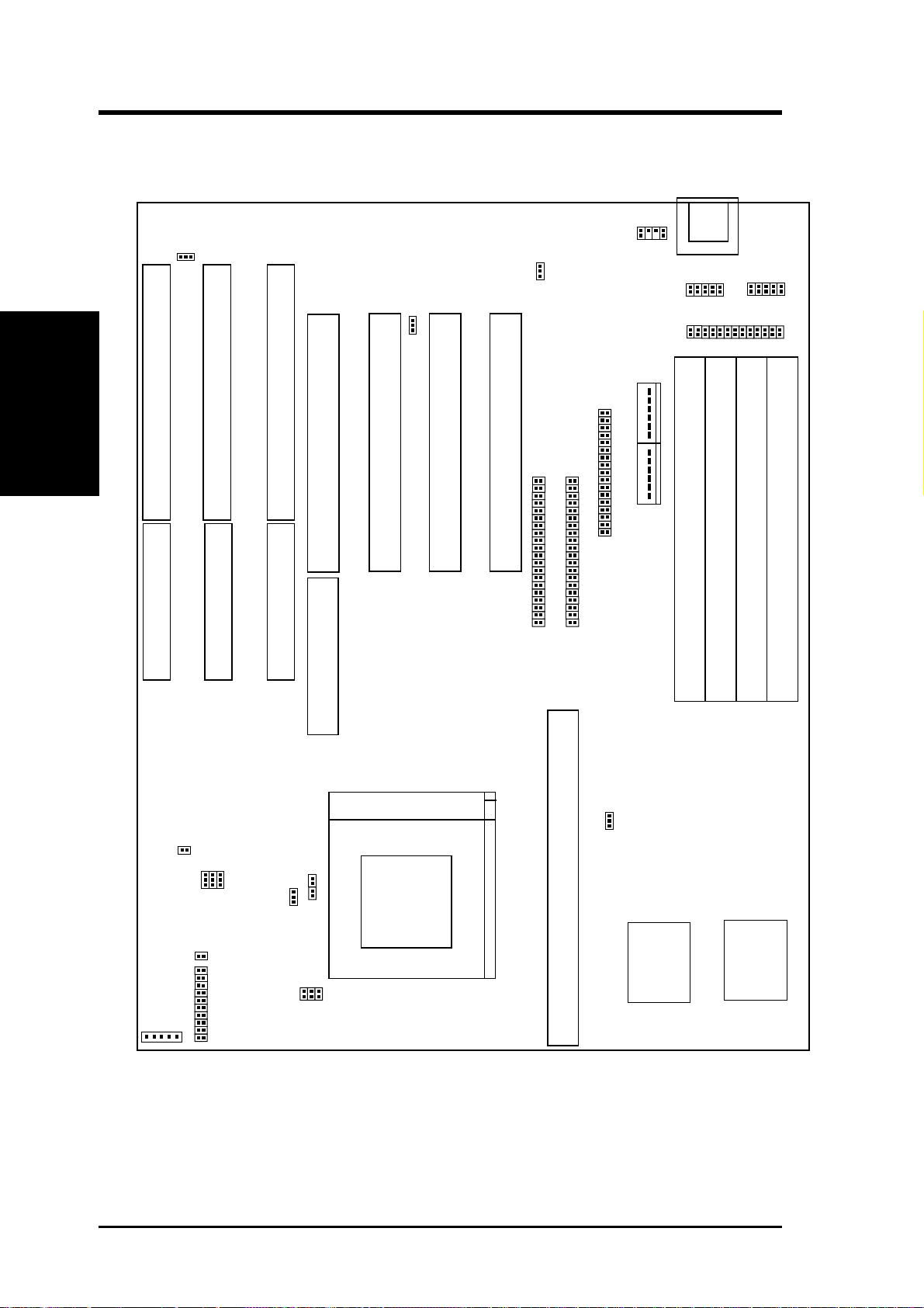
Map of the Motherboard
(Map of Board)
III. INSTALLATION
ISA Slot 3
ISA Slot 2
ISA Slot 1
PCI Slot 4 / MediaBus 2.0
PCI Slot 2
PCI Slot 1
SIMM Slot 1 (Bank 0)
SIMM Slot 2 (Bank 0)
SIMM Slot 3 (Bank 1)
SIMM Slot 4 (Bank 1)
CPU ZIF Socket 8
Keyboard
PCI Slot 3
IDE LED JP17
Floppy Drives
Parallel Printer
PS/2
Mouse
Secondary IDE
Primary IDE
Case Conn (CON 1)
Infrared
JP31
Pipelined Burst Level 2 Cache Expansion Slot
JP13
JP22
JP23
JP24
JP26
JP27
JP28
JP15
JP14
JP16
JP4
JP5
JP7
256 Onboard PB L2 Cache
COM 2
COM 1
JP30
Board Power Input
P8
P9

P/I-P55TP4N User's Manual
5
III. INSTALLATION
Jumpers
1) JP4 p. 8 Multi-I/O Selection (Enable/Disable)
2) JP5 p. 8 Flash ROM Boot Block Program (Enable/Disable)
3) JP16 p. 9 Total Level 2 Cache Size Setting
4) JP22, 23, 24 p. 9 Voltage Regulator Output Selection
5) JP26, 27, 28 p. 10 CPU External Clock (BUS) Frequency Selection
6) JP14, 15 p. 10 CPU:BUS Frequency Ratio
7) JP7 p. 11 PS/2 Mouse on IRQ12 (Enable/Disable)
8) JP13 p. 11 CMOS RAM (Operation/Clear CMOS Data)
Expansion Slots
1) SIMM Slots p. 12 DRAM Memory Expansion slots
2) Cache Expansion p. 14 Socket for Pipelined Burst SRAM Cache Module
3) CPU ZIF Socket 7 p. 15 Socket for Central Processing Unit (CPU)
4) ISA Slots 1,2,3 p. 16 16-bit ISA Bus Expansion slots
5) PCI Slots 1,2,3 p. 16 32-bit PCI Bus Expansion slots
6) PCI 4 / MediaBus p. 18 32-bit PCI Bus Slot and MediaBus
Connectors
1) Keyboard p. 19 Keyboard connector (5-pin Female)
2) PS/2 Mouse p. 19 PS/2 Mouse connector (6-pin Block)
3) Parallel Port p. 20 Parallel Port connector (26-pin Block)
4) Serial Port p. 20 Serial Port COM1 & COM2 (10-pin Blocks)
5) Floppy Drive p. 21 Floppy Drive connector (34-pin Block)
6) Power Input p. 21 Motherboard Power connector (12-pin Block)
7) Primary/Second IDE p. 22 Primary/Secondary IDE connector (40-pin Blocks)
8) JP30 (Fan) p. 22 CPU 12V Cooling Fan connector
9) T urbo/Power (CON1) p. 23 Turbo LED/Power LED (2-pins)
10)SMI Switch (CON1) p. 23 SMI Switch lead (2-pins)
11)Reset Switch (CON1) p. 23 Reset Switch lead (2-pins)
12)Key Lock (CON1) p. 23 Keyboard Lock Switch lead (5-pins)
13)Speaker (CON1) p. 23 Speaker connector (4-pins)
14)JP17 (LED) p. 24 IDE LED activity light
16)JP31 (IR) p. 24 Infrared Port Module connector
(Map of Board)
III. INSTALLATION

P/I-P55TP4N User's Manual
6
(Jumpers)
III. INSTALLATION
III. INSTALLATION
Installation Steps
Before using your computer, you must follow the six steps as follows:
1. Set Jumpers on the Motherboard
2. Install DRAM Modules
3. Install the CPU
4. Install Expansion Cards
5. Connect Cables, Wires, and Power Supply
6. Setup the BIOS Software
1. Jumpers
Several hardware settings are made through the use of jumper caps to con-
nect jumper pins (JP) on the motherboard. See "Map of the Motherboard"
on page 4 for locations of jumpers. The jumper settings will be described
numerically such as [----], [1-2], [2-3] for no connection, connect pins 1&2,
and connect pins 2&3 respectively . Pin 1 for our motherboards is always on
top
Pin 1
or on the left
Pin 1
when holding the motherboard with the key-
board connector away from yourself. A "1" is written besides pin 1 on
jumpers with three pins. The jumpers will also be shown graphically such
as to connect pins 1&2 and to connect pins 2&3. Jumpers with
two pins will be shown as for short and for open. For manufactur-
ing simplicity , the jumpers may be sharing pins from other groups. Use the
diagrams in this manual instead of following the pin layout on the board.
Settings with two jumper numbers require that both jumpers be moved to-
gether . To connect the pins, simply place a plastic jumper cap over the two
pins as diagramed.

P/I-P55TP4N User's Manual
7
III. INSTALLATION
III. INSTALLATION
(Jumpers)
WARNING: Some pins are used for connectors or power sources.
These are clearly separated from jumpers in "Map of the Motherboard"
on page 4. Placing jumper caps over these will cause damage to your
motherboard.
WARNING: Computer motheboards and components contain very
delicate Integrated Circuit (IC) chips. To protect the motherboard and
other components against damage from static electricity, you should
follow some precautions whenever you work on your computer.
1. Unplug your computer when working on the inside.
2. Hold components by the edges and try not to touch the IC chips.
3. Use a grounded wrist strap before handling computer components.
4. Place components on a grounded antistatic pad or on the bag that
came with the component whenever you work on lay down
components.
P/I-P55TP4N User's Manual
8
III. INSTALLATION
(Jumpers)
III. INSTALLATION
Jumper Settings
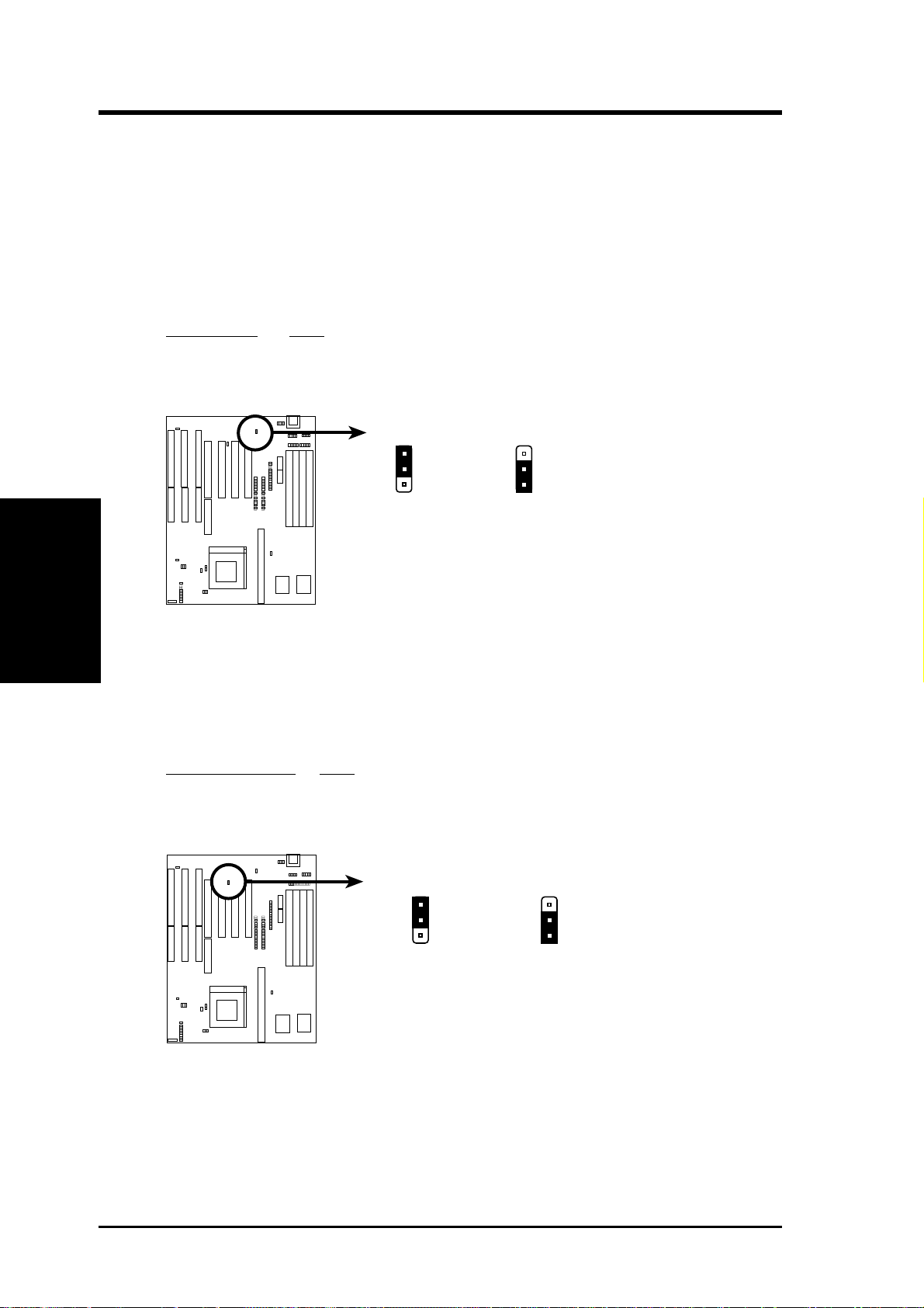
1. Onboard Multi-I/O Selection (JP4)
You can selectively disable each onboard Multi-I/O item (floppy, serial,
parallel, and IrDA) through BIOS (see page 35) or disable all Multi-I/O
items at once with the following jumper in order to use your own Multi-
I/O card.
Selections JP4
Enable [1-2] (Default)
Disable [2-3]
1
Multi I/O Setting (Enable / Disable)
2
3
JP4
Enable (Default) Disabled
1
2
3
JP4
2. Flash ROM Boot Block Programming (JP5)
This sets the operation mode of the boot block area of the BIOS Flash
ROM to allow programming in the Enabled position.
Programming JP5
Disabled [1-2] (Default)
Enabled [2-3]
Boot Block Programming (Disable / Enable)
Disabled (Default)
Enabled
1
2
3
1
2
3
JP5
JP5
P/I-P55TP4N User's Manual
9
III. INSTALLATION
(Jumpers)
III. INSTALLATION
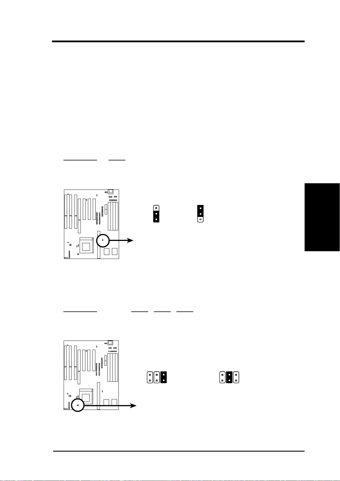
3. Total Level 2 Cache Size Setting (JP16)
This jumper sets the total amount of L2 cache that is present. If you
have two cache chips onboard (see "Map of Motherboard" for locations),
then you have either 256KB or 512KB. An "ASUS" or "COAST" cache
module can be used to upgrade the 256KB version to 512KB. If there is
no onboard cache, you must install a cache module of either 256KB or
512KB. IMPORTANT: See page 14 "SRAM Cache" for installa-
tion procedures. Regardless of your cache combination, set the fol-
lowing jumpers according to the total amount of L2 cache that is present
onboard and installed as a module.
Selections JP16
256KB [2-3] (Default)
512KB [1-2]
Total L2 Cache Size Setting (256KB / 512KB)
1
2
3
256KB 512KB
1
2
3
JP16
JP16
4. Voltage Regulator Output Selection (JP22, 23, 24)
These jumpers set the voltage supplied to the CPU.
Selections JP24 JP23 JP22
STD 3.3V-3.465V [open] [open] [short] (Default)
VRE 3.4V-3.6V [open] [short][open]
Voltage Regulator Output Selection (STD / VRE)
STD 3.3V - 3.465V
(Default)
VRE 3.4V - 3.6V
JP24
JP23
JP22
JP24
JP23
JP22
P/I-P55TP4N User's Manual
10
III. INSTALLATION
(Jumpers)
III. INSTALLATION
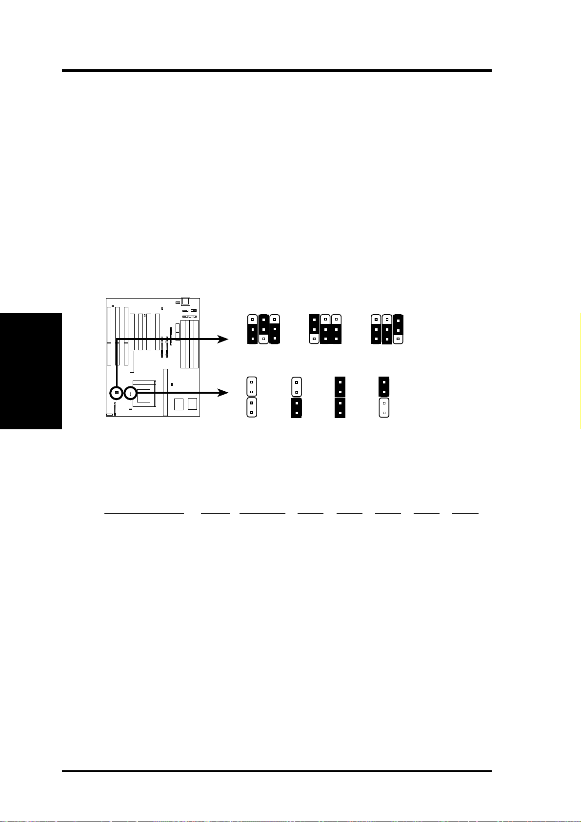
5. CPU External (BUS) Frequency Selection (JP26, 27, 28)
These jumpers tells the clock generator what frequency to send to the
CPU. These allow the selection of the CPU’s External frequency (or
BUS Clock). The BUS Clock times the BUS Ratio equals the CPU's
Internal frequency (the advertised CPU speed).
6. CPU to BUS Frequency Ratio (JP14, 15)
These jumpers set the frequency ratio between the Internal frequency of
the CPU and the External frequency (called the BUS Clock) within the
CPU. These must be set together with the above jumpers CPU External
(BUS) Frequency Selection.
CPU External Clock (BUS) Frequency Selection
CPU : BUS Frequency Ratio (1.5x, 2.0x, 2.5x, 3.0x)
1.5 x 2.0 x
2.5 x
3.0 x
60MHz
50MHz
JP26
1
2
3
JP27
JP28
JP26
1
2
3
JP27
JP28
66MHz
JP26
1
2
3
JP27
JP28
JP14
JP15
JP14
JP15
JP14
JP15
JP14
JP15
Set the jumpers by the Internal speed of the Intel CPU as follows:
Internal (CPU) Ratio External JP28 JP27 JP26 JP14 JP15
166MHz 2.5x 66MHz [2-3] [1-2] [2-3] [short] [short]
150MHz 2.5x 60MHz [1-2] [2-3] [2-3] [short] [short]
133MHz 2.0x 66MHz [2-3] [1-2] [2-3] [open] [short]
120MHz 2.0x 60MHz [1-2] [2-3] [2-3] [open] [short]
100MHz 1.5x 66MHz [2-3] [1-2] [2-3] [open] [open]
90MHz 1.5x 60MHz [1-2] [2-3] [2-3] [open] [open]
75MHz 1.5x 50MHz [2-3] [2-3] [1-2] [open] [open]

P/I-P55TP4N User's Manual
11
III. INSTALLATION
(Jumpers)
III. INSTALLATION
7. PS/2 Mouse on IRQ12 Setting (JP7)
This jumper enables or disables the onboard PS/2 mouse lead connector .
When Enabled, the port becomes active and uses IRQ12. When
Disabled, IRQ12 will be freed for use by a PCI or ISA expansion card.
See Page 19 for the "PS/2 Mouse connector."
Selections JP7
Disable [2-3] (Default)
Enable [1-2]
1
JP7
PS/2 Mouse on IRQ 12 (Disable / Enable)
JP7
23 123
Disabled (Default)
Enabled
8. CMOS RAM (JP13)
This clears the user-entered information stored in the Dallas DS12887A
Chip such as hard disk information and passwords. Simply connect a
jumper cap over this jumper for a few seconds then remove. Make sure
that your computer is turned off. You must enter the BIOS setup (by
holding down <DEL> during power-up) after this is done to re-enter
BIOS information (see BIOS SETUP).
Selections JP13
Operation [open] (Default)
Clear CMOS Data [short] (momentarily)
CMOS RAM (Operation / Clear CMOS Data)
JP13
Operation (Default)
Clear CMOS Data
JP13
Note: Dallas DS12B887 chips and Benchmarq BQ3287A chips require
that you power on with the jumper shorted as in the following procedures:
(1) Short Jumper (while the computer is off), (2) Power on, (3) Power off,
(4) Open Jumper, (5) Power on, (6) Setup BIOS (hold down <DEL>)
P/I-P55TP4N User's Manual
12
III. INSTALLATION
III. INSTALLATION
(Memory)
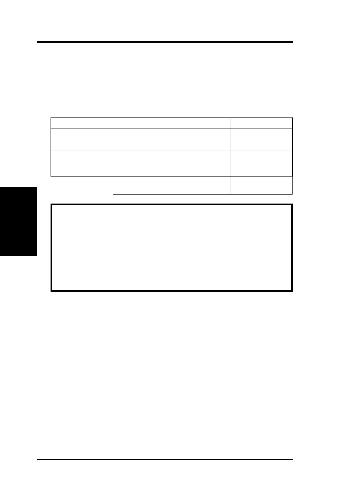
2. System Memory (DRAM)
This motherboard supports four 72-pin SIMMs of 4MB, 8MB, 16MB, or
32MB to form a memory size between 8MB to 128MB. For BUS frequen-
cies of 50MHz or 60MHz, you can use either 60ns or 70ns modules. For
BUS frequencies of 66MHz, you must use 60ns modules.
Total System Memory =
IMPORTANT: Each bank must have the same size memory installed
in pairs.
IMPORTANT: Do not use memory modules with more than 24 chips
per module. Modules with more than 24 chips exceed the design speci-
fications of the memory subsystem and will cause unreliable opera-
tion.
IMPORTANT: Do not use SIMM Modules that use an extra TTL
chip to convert the memory module from asymmetric to symmetric.
Install memory in any or all of the banks in any combination as follows:
Bank Memory Module Total Memory
Bank 0 4MB, 8MB, 16MB, 32MB x2
SIMM Slots 1&2 72-pin FPM or EDO SIMM
Bank 1 4MB, 8MB, 16MB, 32MB x2
SIMM Slots 3&4 72-pin FPM or EDO SIMM
P/I-P55TP4N User's Manual
13
III. INSTALLATION
(DRAM Memory)
III. INSTALLATION
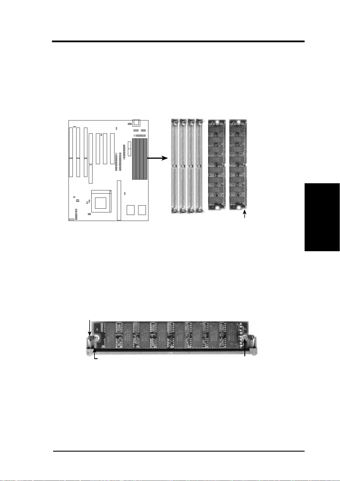
DRAM Memory Installation Procedures:
1. The SIMM memory modules will only fit in one orientation as shown
because of a "Plastic Safety Tab" on one end of the SIMM slots which
requires the "Notched End" of the SIMM memory modules.
72 Pin SIMM DRAM Slots & Module
1234
Notched End
2. Press the memory module firmly into place starting from a 45 degree
angle making sure that all the contacts are aligned with the slot.
3. With your finger tips, rock the memory module into a vertical position
so that it clicks into place.
Metal Clip
Plastic Safety Tab (This Side Only)
Mounting Hole
72 Pin DRAM in SIMM Socket
4. The plastic guides should go through the two "Mounting Holes" on the
sides and the "Metal Clips" should snap on the other side.
5. To release the memory module, squeeze both "Metal Clips" outwards
and rock the module out of the "Metal Clips".

P/I-P55TP4N User's Manual
14
(SRAM Cache)
III. INSTALLATION
III. INSTALLATION
Level 2 External Static RAM (SRAM) Cache
The motherboard you purchase may either have 0KB, 256KB, or 512KB.
Most likely you will have two cache chips onboard (see "Map of Mother-
board" for locations), then you have 256KB pipelined bust SRAM cache. A
cache module can be used to upgrade the 256KB version to 512KB and the
0KB version to 256KB or 512KB.
IMPORTANT: You must set jumper 16 "Total Level 2 Cache Size Set-
ting" on page 9 when changes are made to your cache size.
Insert the module as shown. Because the number of pins are different on
either side of the break, the module will only fit in the orientation as shown.
Compatible Cache Modules for Motherboard PCB 1.01
NOTE: Motherboard PCB 1.0 can only use ASUS CM1 Rev. 1.6 to up-
grade the 256KB version to 512KB. 0KB version can use all modules for
upgrade to 256KB or 512KB except the ASUS CM1 Rev. 1.6.
256KB PB Cache Module
42 Pins
38 Pins
SIMM Cache Module 256KB to 512KB 0KB to 256/ 512KB
ASUS CM1 Rev 1.0 No Yes
ASUS CM1 Rev 1.3 No Yes
ASUS CM4 Rev 1.5 No Yes
ASUS CM1 Rev 1.6 Yes No
ASUS CM1 Rev 3.0 Yes Yes
COAST 1.1 Yes Yes
COAST 1.2 Yes Yes
COAST 1.3 Yes Yes
COAST 2.0 Yes Yes
COAST 2.1 Yes Yes
COAST 3.0 Yes Yes
 Loading...