

V-Series P5V900
R
R
ASUS PC (Desktop Barebone)
E 3 0 7 1
F i r s t E d i t i o n
D e c e m b e r 2 0 0 6
Copyright © 2006 ASUSTeK COMPUTER INC. All Rights Reserved.
No part of this manual, including the products and software described in it, may be reproduced,
transmitted, transcribed, stored in a retrieval system, or translated into any language in any form
or by any means, except documentation kept by the purchaser for backup purposes, without the
express written permission of ASUSTeK COMPUTER INC. (“ASUS”).
Product warranty or service will not be extended if: (1) the product is repaired, modied or
altered, unless such repair, modication of alteration is authorized in writing by ASUS; or (2) the
serial number of the product is defaced or missing.
ASUS PROVIDES THIS MANUAL “AS IS” WITHOUT WARRANTY OF ANY KIND, EITHER EXPRESS
OR IMPLIED, INCLUDING BUT NOT LIMITED TO THE IMPLIED WARRANTIES OR CONDITIONS OF
MERCHANTABILITY OR FITNESS FOR A PARTICULAR PURPOSE. IN NO EVENT SHALL ASUS,
ITS DIRECTORS, OFFICERS, EMPLOYEES OR AGENTS BE LIABLE FOR ANY INDIRECT, SPECIAL,
INCIDENTAL, OR CONSEQUENTIAL DAMAGES (INCLUDING DAMAGES FOR LOSS OF PROFITS, LOSS
OF BUSINESS, LOSS OF USE OR DATA, INTERRUPTION OF BUSINESS AND THE LIKE), EVEN IF ASUS
HAS BEEN ADVISED OF THE POSSIBILITY OF SUCH DAMAGES ARISING FROM ANY DEFECT OR
ERROR IN THIS MANUAL OR PRODUCT.
SPECIFICATIONS AND INFORMATION CONTAINED IN THIS MANUAL ARE FURNISHED FOR
INFORMATIONAL USE ONLY, AND ARE SUBJECT TO CHANGE AT ANY TIME WITHOUT NOTICE, AND
SHOULD NOT BE CONSTRUED AS A COMMITMENT BY ASUS. ASUS ASSUMES NO RESPONSIBILITY
OR LIABILITY FOR ANY ERRORS OR INACCURACIES THAT MAY APPEAR IN THIS MANUAL,
INCLUDING THE PRODUCTS AND SOFTWARE DESCRIBED IN IT.
Products and corporate names appearing in this manual may or may not be registered
trademarks or copyrights of their respective companies, and are used only for identication or
explanation and to the owners’ benet, without intent to infringe.
i i
Table of contents
Notices ................................................................................................ vi
Safety information ..............................................................................vii
About this guide ................................................................................. viii
System package contents .................................................................... x
C h a p t e r 1 : S y s t e m I n t r o d u c t i o n
1.1 Welcome! .............................................................................. 1-2
1.2 Front panel (external) ...........................................................
1.3 Rear panel .............................................................................
1.4 Internal components .............................................................
C h a p t e r 2 : B a s i c I n s t a l l a t i o n
2.1 Preparation ........................................................................... 2-2
2.2 Before you proceed ..............................................................
2.3 Removing the side cover and front panel assembly .............
2.4 Central Processing Unit (CPU) ..............................................
2.4.1 Overview .................................................................
2.4.2 Installing the CPU ....................................................
2.4.3 Installing the CPU fan and heatsink assembly .........
2.5 Installing a DIMM ...................................................................
2.5.1 Memory congurations ...........................................
2.5.2 Installing a DDR2 DIMM .........................................
2.5.3 Removing a DDR2 DIMM ........................................
2.6 Expansion slots ...................................................................
2.6.1 Installing an expansion card ..................................
2.6.2 Conguring an expansion card ..............................
2.6.3 PCI Express x1 slot ...............................................
2.6.4 PCI slots ................................................................
2.6.5 PCI Express x16 slot .............................................
2.7 Installing an optical drive ....................................................
2.8 Installing a hard disk drive ..................................................
2.9 Installing a oppy disk drive
2.10 Re-connecting cables ..........................................................
2.11 Reinstalling the cover .........................................................
................................................ 2-20
1-2
1-4
1-7
2-2
2-3
2-4
2-4
2-4
2-6
2-8
2-8
2-11
2-11
2-12
2-12
2-12
2-14
2-14
2-14
2-15
2-17
2-21
2-22
i i i
Table of contents
C h a p t e r 3 : S t a r t i n g u p
3.1 Installing an operating system .............................................. 3-2
3.2 Powering up ..........................................................................
3.3 Support CD information ........................................................
3.3.1 Running the support CD ..........................................
3.3.2 Utilities menu ..........................................................
3.3.3 Make disk ................................................................
3.3.4 Manual .....................................................................
3.3.5 ASUS Contact information ......................................
3.4 Software information ............................................................
C h a p t e r 4 : M o t h e r b o a r d I n f o
4.1 Introduction .......................................................................... 4-2
4.2 Motherboard layout ..............................................................
4.3 Jumpers ................................................................................
4.4 Connectors ...........................................................................
3-2
3-2
3-3
3-4
3-5
3-5
3-6
3-7
4-2
4-3
4-6
i v

Table of contents
5.2.4 Menu items ........................................................... 5-13
5.2.5 Sub-menu items ....................................................
5.2.6 Conguration elds ...............................................
5.2.7 Pop-up window ......................................................
5.2.8 General help ..........................................................
5.3 Main menu ...........................................................................
5.3.1 System Time ........................................................
5.3.2 System Date ........................................................
5.3.3 Primary IDE Master/Slave ......................................
5.3.4 SATA 1/2
5.3.5 HDD SMART Monitoring .........................................
5.3.6 Installed Memory ...................................................
5.3.7 Usable Memory ......................................................
5.4 Advanced menu ..................................................................
5.4.1 CPU Conguration .................................................
5.4.2 Chipset ..................................................................
5.4.3 PCIPnP ...................................................................
5.4.4 Onboard Device Conguration ..............................
5.4.5 USB Conguration .................................................
5.5 Power menu ........................................................................
5.5.1 ACPI Suspend Type ...............................................
5.5.2 ACPI APIC Support ................................................
5.5.3 APM Conguration ................................................
5.5.4 Hardware Monitor ..................................................
5.6 Boot menu ..........................................................................
5.6.1 Boot Device Priority ..............................................
5.6.2 Boot Settings Conguration .................................
5.6.3 Security .................................................................
5.7 Tool menu ...........................................................................
5.8 Exit menu ............................................................................
.............................................................. 5-18
5-13
5-13
5-14
5-14
5-15
5-15
5-15
5-16
5-19
5-19
5-19
5-19
5-20
5-21
5-22
5-23
5-24
5-25
5-25
5-25
5-26
5-28
5-30
5-30
5-31
5-32
5-33
5-33
v

Notices
v i
Safety information
E l e c t r i c a l s a f e t y
•
To prevent electrical shock hazard, disconnect the power cable from
the electrical outlet before relocating the system.
•
When adding or removing devices to or from the system, ensure that
the power cables for the devices are unplugged before the signal cables
are connected.
•
If the power supply is broken, do not try to fix it by yourself. Contact a
qualified service technician or your retailer.
O p e r a t i o n s a f e t y
•
Before installing devices into the system, carefully read all the
documentation that came with the package.
•
Before using the product, make sure all cables are correctly connected
and the power cables are not damaged. If you detect any damage,
contact your dealer immediately.
•
To avoid short circuits, keep paper clips, screws, and staples away from
connectors, slots, sockets and circuitry.
•
Avoid dust, humidity, and temperature extremes. Do not place the
product in any area where it may become wet. Place the product on a
stable surface.
•
If you encounter technical problems with the product, contact a
qualified service technician or your retailer.
Lithium-Ion Battery Warning
CAUTION: Danger of explosion if battery is incorrectly replaced.
Replace only with the same or equivalent type recommended by
the manufacturer. Dispose of used batteries according to the
manufacturer’s instructions.
VORSICHT: Explosionsgetahr bei unsachgemäßen Austausch der
Batterie. Ersatz nur durch denselben oder einem vom Hersteller
empfohlenem ähnljchen Typ. Entsorgung gebrauchter Batterien nach
Angaben des Herstellers.
LASER PRODUCT WARNING
C L A S S 1 L A S E R P R O D U C T
v i i
About this guide
A u d i e n c e
This guide provides general information and installation instructions about
the ASUS V-Series P5V900 barebone system. This guide is intended for
experienced users and integrators with hardware knowledge of personal
computers.
How t hi s g ui de is o rg ani ze d
This guide contains the following parts:
1 . C h a p t e r 1 : S y s t e m i n t r o d u c t i o n
This chapter gives a general description of the ASUS
V-Series P5V900. The chapter lists the system features, including
introduction on the front and rear panel, and internal components.
2 . C h a p t e r 2 : B a s i c i n s t a l l a t i o n
This chapter provides step-by-step instructions on how to install
components in the system.
3 . C h a p t e r 3 : S t a r t i n g u p
This chapter helps you power up the system and install drivers and
utilities from the support CD.
4 . C h a p t e r 4 : M o t h e r b o a r d i n f o r m a t i o n
This chapter gives information about the motherboard that comes
with the system. This chapter includes the motherboard layout,
jumper settings, and connector locations.
5 . C h a p t e r 5 : B I O S i n f o r m a t i o n
This chapter tells how to change system settings through the BIOS
Setup menus and describes the BIOS parameters.
v i i i
C o n v e n t i o n s u s e d i n t h i s g u i d e
WARNING: Information to prevent injury to yourself when trying
to complete a task.
CAUTION: Information to prevent damage to the components
when trying to complete a task.
IMPORTANT: Instructions that you MUST follow to complete a
task.
NOTE: Tips and additional information to aid in completing a
task.
W h e r e t o f i n d m o r e i n f o r m a t i o n
Refer to the following sources for additional information and for product
and software updates.
1 . A S U S W e b s i t e s
The ASUS websites worldwide provide updated information on
ASUS hardware and software products. Refer to the ASUS contact
information.
2 . O p t i o n a l D o c u m e n t a t i o n
Your product package may include optional documentation, such as
warranty yers, that may have been added by your dealer. These
documents are not part of the standard package.
i x
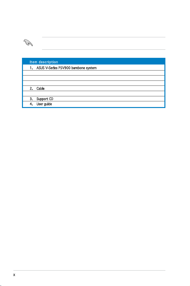
System package contents
Check your V-Series P5V900 system package for the following items.
If any of the items is damaged or missing, contact your retailer
immediately.
I te m d e s c ri p t i o n
1. ASUS V-Series P5V900 barebone system with
• ASUS motherboard
• 300 W (peak) PFC power supply unit
• ASUS chassis
2. Cable
• AC power cable
3. Support CD
4. User guide
x

R
R
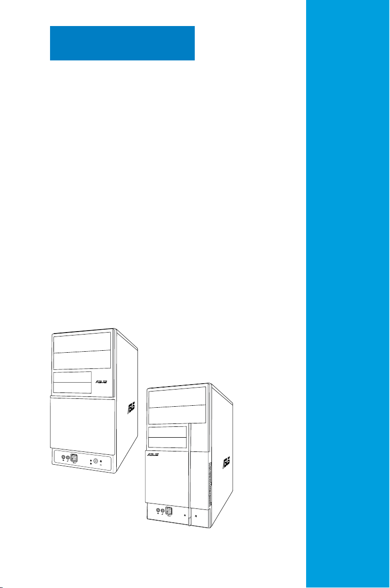
Chapter 1
This chapter gives a general
description of the ASUS
V-Series P5V900. The chapter
lists the system features including
introduction on the front and rear
panel, and internal components.
System introduction

1 - 2
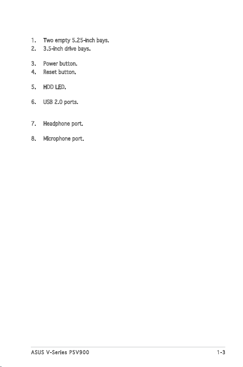
1. Two empty 5.25-inch bays. These bays are for IDE optical drives.
2. 3.5-inch drive bays. These slots are for 3.5-inch oppy or hard disk
drives.
3. Power button. Press this button to turn the system on.
4. Reset button. Press this button to reboot the system without turning
off the power.
5. HDD LED. This LED lights up when data is read from or written to the
hard disk drive.
6. USB 2.0 ports. These Universal Serial Bus 2.0 (USB 2.0) ports are
available for connecting USB 2.0 devices such as a mouse, printer,
scanner, camera, PDA, and others.
7. Headphone port. This Line In (green) port connects a headphone with
a stereo mini-plug.
8. Microphone port. This Mic (pink) port connects a microphone.
1 - 3A S U S V - S e r i e s P 5 V 9 0 0
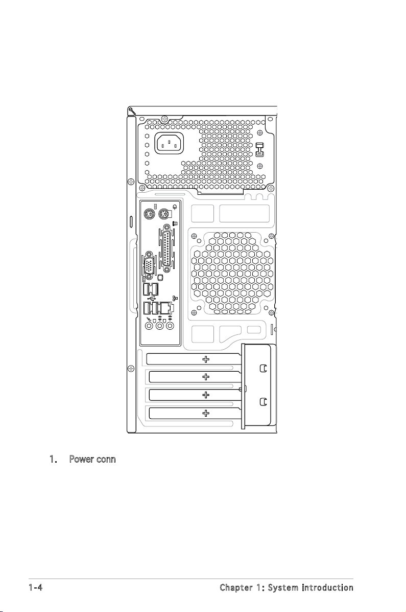
1.3 Rear panel
The system rear panel includes the power connector and several I/O ports
that allow convenient connection of devices.
1 - 4 C h a p t e r 1 : S y s t e m i n t r o d u c t i o n
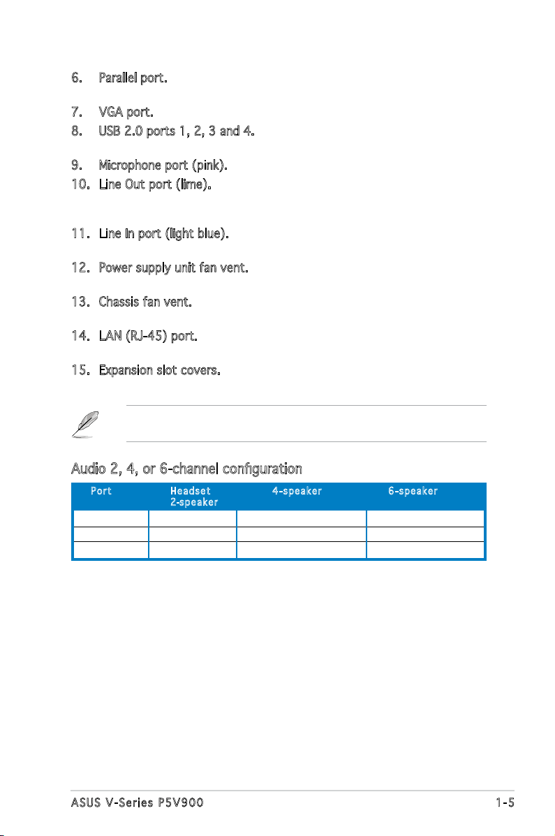
6. Parallel port. This 25-pin port connects a printer, scanner, or other
devices.
7. VGA port. This port connects a VGA monitor.
8. USB 2.0 ports 1, 2, 3 and 4. These 4-pin Universal Serial Bus (USB)
ports are available for connecting USB 2.0 devices.
9. Microphone port (pink). This port connects a microphone.
10. Line Out port (lime). This port connects a headphone or a speaker.
In 4-channel and 6-channel conguration, the function of this port
becomes Front Speaker Out.
11. Line In port (light blue). This port connects the tape, CD, DVD player,
or other audio sources.
12. Power supply unit fan vent. This vent is for the PSU fan that provides
ventilation inside the power supply unit.
13. Chassis fan vent. This vent is for the fan that provides ventilation
inside the system chassis.
14. LAN (RJ-45) port. This port allows Gigabit connection to a Local Area
Network (LAN) through a network hub.
15. Expansion slot covers. Remove these covers when installing expansion
cards.
Refer to the audio conguration table below for the function of the audio
ports in 2, 4, or 6-channel conguration.
Audio 2, 4, or 6-channel conguration
P or t He a d s e t 4 -s p e a k e r 6- s p e a ke r
2-s pe a k e r
Light Blue Line In Surround Out Surround Out
Lime Line Out Front Speaker Out Front Speaker Out
Pink Mic In Mic In Center/Bass
1 - 5A S U S V - S e r i e s P 5 V 9 0 0
1 - 6 C h a p t e r 1 : S y s t e m i n t r o d u c t i o n
R
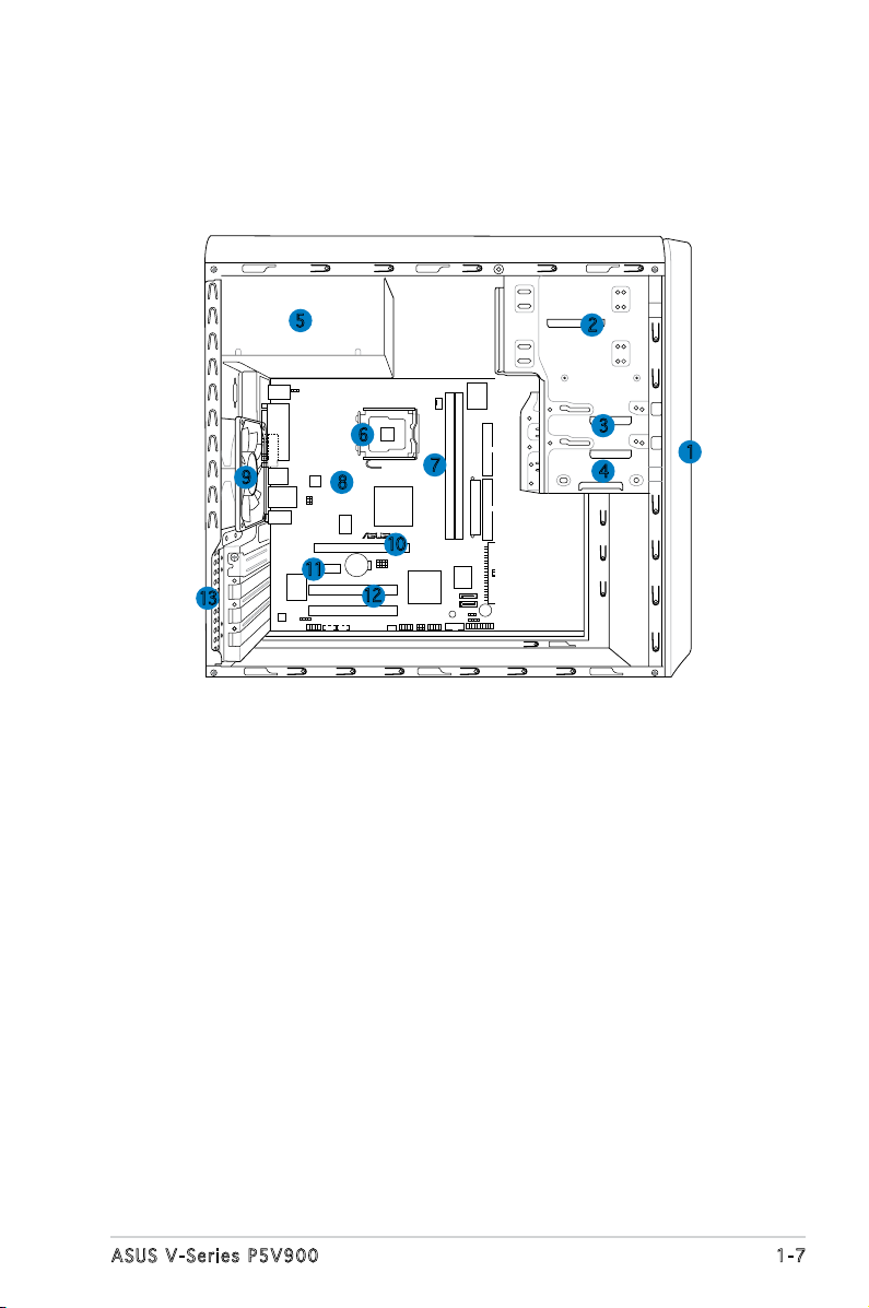
1.4 Internal components
The illustration below is the internal view of the system when you remove
the top cover and the power supply unit. The installed components are
labeled for your reference. Proceed to Chapter 2 for instructions on
installing additional system components.
5
6
9
13
8
10
11
12
1. Front panel cover
2. 5.25-inch optical drive bays
3. Hard disk drive bay
4. Floppy disk drive bay
5. Power supply unit
6. CPU socket
7. DIMM sockets
2
3
7
4
8. ASUS motherboard
9. Chassis fan
10. PCI Express x16 slot
11. PCI Express x1 slot
12. PCI slots
13. Metal bracket lock
1
1 - 7A S U S V - S e r i e s P 5 V 9 0 0
1 - 8 C h a p t e r 1 : S y s t e m i n t r o d u c t i o n
R
R
Chapter 2
This chapter provides step-by-step
instructions on how to install
components in the system.
Basic installation
2.1 Preparation
Before you proceed, make sure that you have all the components you plan
to install in the system.
2 - 2 C h a p t e r 2 : B a s i c i n s t a l l a t i o n

2 - 3
2.4 Central Processing Unit (CPU)
2 - 4 C h a p t e r 2 : B a s i c i n s t a l l a t i o n
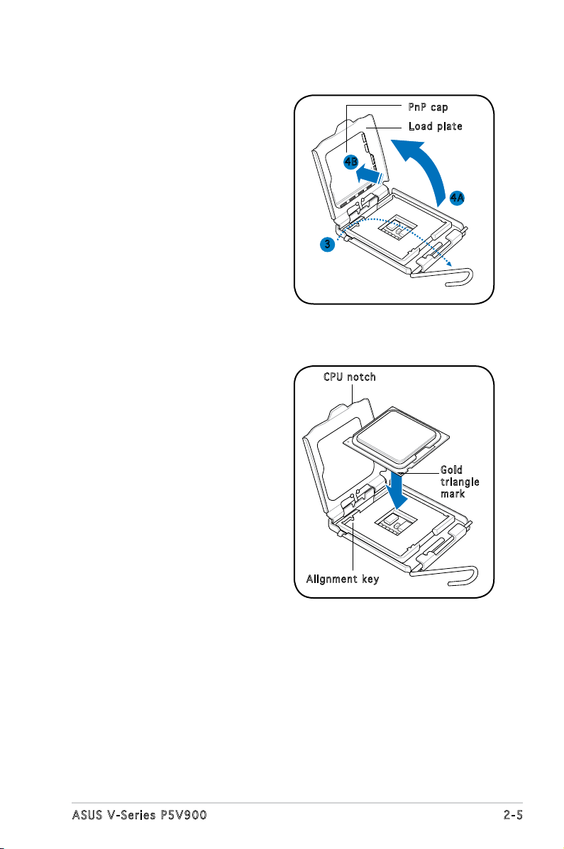
3. Lift the load lever in the
direction of the arrow to a 135º
angle.
P nP c a p
L oa d p l a t e
4. Lift the load plate with your
thumb and forenger to a 100º
angle (4A), then push the PnP
cap from the load plate window
to remove (4B).
5. Position the CPU over the
socket, making sure that
the gold triangle is on the
bottom-left corner of the socket
then t the socket alignment
key into the CPU notch.
4 B
4 A
3
C PU n o t c h
G ol d
t ri a n g l e
m ar k
A li g n m e n t k e y
2 - 5A S U S V - S e r i e s P 5 V 9 0 0
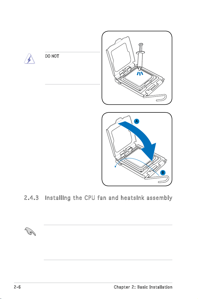
6. Apply Thermal Interface Material
on the CPU before closing the
load plate.
DO NOT eat the Thermal
Interface Material. If it gets
into your eyes or touches
your skin, make sure to wash
it off immediately, and seek
professional medical help.
7. Close the load plate (A), then
push the load lever (B) until it
snaps into the retention tab.
A
B
2 . 4 . 3 I n s t a l l i n g t h e C P U f a n a n d h e a t s i n k a s s e m b l y
The Intel® Pentium® 4 LGA775 processor requires a specially designed
heatsink and fan assembly to ensure optimum thermal condition and
performance.
• When you buy a boxed Intel® Pentium® 4 processor, the package
includes the CPU fan and heatsink assembly. If you buy a
CPU separately, make sure that you use only Intel
multi-directional heatsink and fan.
®
• Your Intel
a push-pin design and requires no tool to install.
2 - 6 C h a p t e r 2 : B a s i c i n s t a l l a t i o n
Pentium® 4 LGA775 heatsink and fan assembly comes in
®
-certied
If you purchased a separate CPU heatsink and fan assembly, make
R
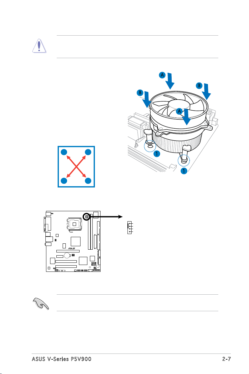
CPU Fan Connector
CPU_FA N
GND
CPU FAN PWR
CPU FAN IN
CPU FAN PWM
sure that the Thermal Interface Material is properly applied to the CPU
heatsink or CPU before you install the heatsink and fan assembly.
To install the CPU heatsink and fan:
1. Place the heatsink on top of the
installed CPU, making sure that
B
A
B
the four fasteners match the
holes on the motherboard.
A
2. Push down two fasteners at
a time in a diagonal sequence
to secure the heatsink and fan
assembly in place.
A
B
B
1
1
A
3. When the fan and heatsink assembly is in place, connect the CPU fan
cable to the connector on the motherboard.
Do not forget to connect the CPU fan connector! Hardware monitoring
errors can occur if you fail to plug this connector.
2 - 7A S U S V - S e r i e s P 5 V 9 0 0
2.5 Installing a DIMM
The system motherboard comes with two Double Data Rate 2 (DDR2) Dual
Inline Memory Module (DIMM) sockets.
The following gure illustrates the location of the sockets:
• Install only identical (the same type and size) DDR2 memory
modules.
• Install only ASUS-certied memory modules. Refer to the DDR2
Qualied Vendors List on the next page for details.
• Always install DIMMs with the same CAS latency. For optimum
compatibility, we recommend that you obtain memory modules from
the same vendor.
2 - 8 C h a p t e r 2 : B a s i c i n s t a l l a t i o n
Q u a l i f i e d V e n d o r s L i s t s ( Q V L )
2 - 9A S U S V - S e r i e s P 5 V 9 0 0
Siz e Ve n d o r Mod e l Side(s) Com p o n ent A B
2 - 1 0 C h a p t e r 2 : B a s i c i n s t a l l a t i o n
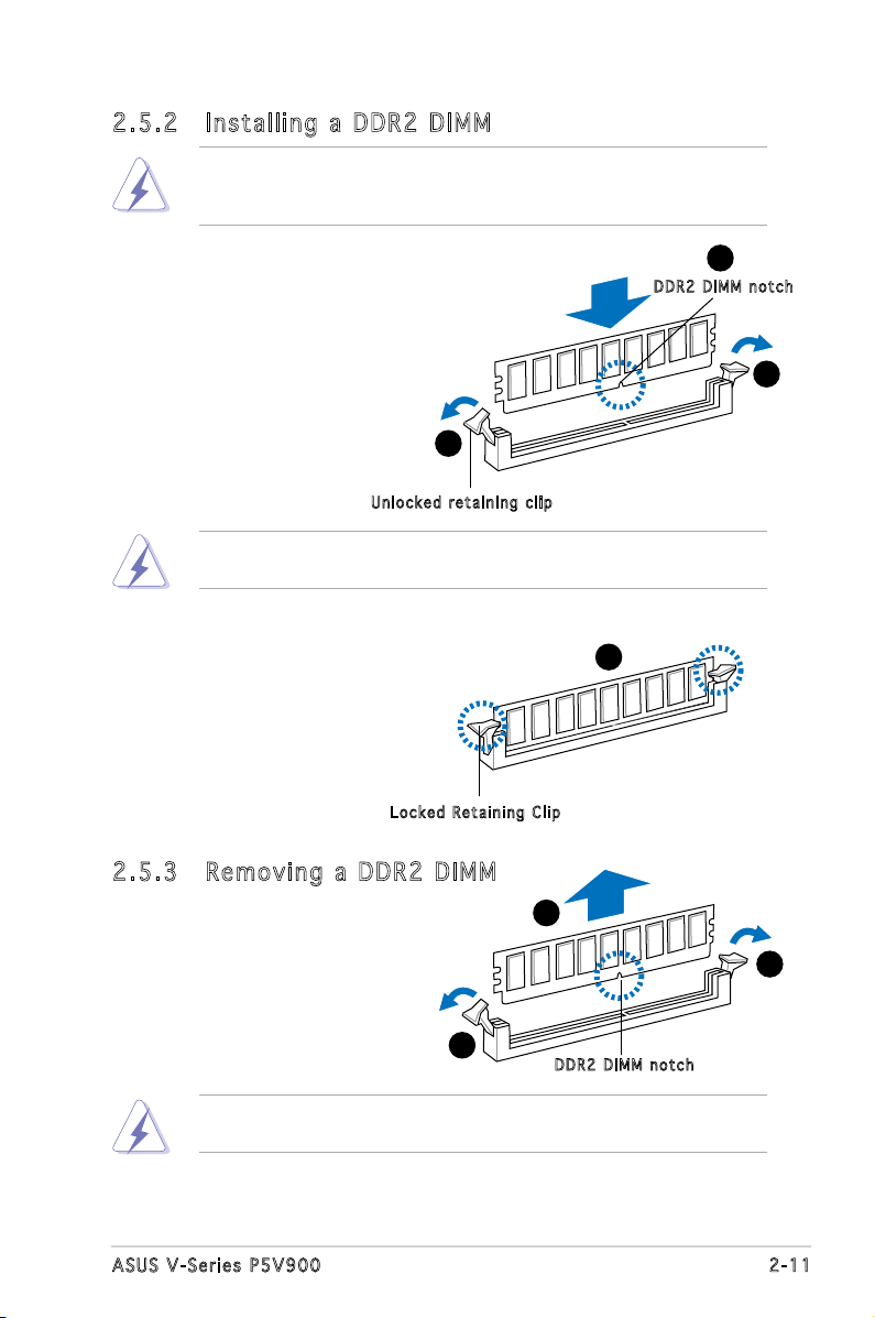
2 . 5 . 2 I n s t a l l i n g a D D R 2 D I M M
Make sure to unplug the power supply before adding or removing DIMMs
or other system components. Failure to do so may cause severe damage
to both the motherboard and the components.
1. Unlock a DDR2 DIMM socket
by pressing the retaining clips
outward.
2. Align a DIMM on the socket
such that the notch on the
DIMM matches the break on
the socket.
U nl o c k e d re t a i n i n g c l i p
A DDR2 DIMM is keyed with a notch so that it ts in only one direction.
DO NOT force a DIMM into a socket to avoid damaging the DIMM.
1
2
D DR 2 D I M M n o t c h
1
3. Firmly insert the DIMM into the
socket until the retaining clips
snap back in place and the DIMM
is properly seated.
L oc k e d R e ta i n i n g Cl i p
2 . 5 . 3 R e m o v i n g a D D R 2 D I M M
Follow these steps to remove a DIMM.
1. Simultaneously press the
retaining clips outward to
unlock the DIMM.
1
Support the DIMM lightly with your ngers when pressing the retaining
clips. The DIMM might get damaged when it ips out with extra force.
2. Remove the DIMM from the socket.
3
2
1
D DR 2 D I M M n o t c h
2 - 1 1A S U S V - S e r i e s P 5 V 9 0 0
2.6 Expansion slots
In the future, you may need to install expansion cards. The following
sub-sections describe the slots and the expansion cards that they support.
Make sure to unplug the power cord before adding or removing
expansion cards. Failure to do so may cause you physical injury and
damage motherboard components.
2 . 6 . 1 I n s t a l l i n g a n e x p a n s i o n c a r d
To install an expansion card:
1. Before installing the expansion card, read the documentation that
came with it and make the necessary hardware settings for the card.
2. Remove the system unit cover (if your motherboard is already
installed in a chassis).
3. Remove the bracket opposite the slot that you intend to use. Keep
the screw for later use.
4. Align the card connector with the slot and press rmly until the card is
completely seated on the slot.
5. Secure the card to the chassis with the screw you removed earlier.
6. Replace the system cover.
2 . 6 . 2 C o n f i g u r i n g a n e x p a n s i o n c a r d
After installing the expansion card, congure it by adjusting the software
settings.
1. Turn on the system and change the necessary BIOS settings, if any.
See Chapter 5 for information on BIOS setup.
2. Assign an IRQ to the card. Refer to the tables on the next page.
3. Install the software drivers for the expansion card.
2 - 1 2 C h a p t e r 2 : B a s i c i n s t a l l a t i o n
 Loading...