


Asus P5K DELUXE WIFI-AP, EATX12V User Manual
ASUS P5K Deluxe 2-3
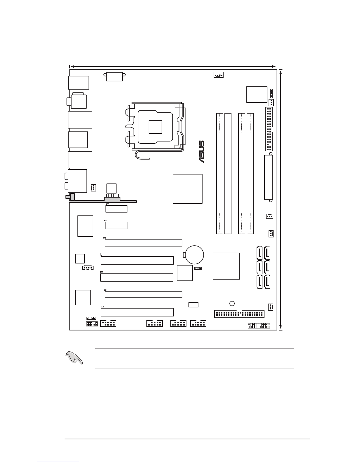
2.2.3 Motherboard layout
PANEL
P5K DELUXE
®
AAFP
CHASSIS
24.5cm (9.6in)
30.5cm (12.0in)
CPU_FAN
DDR2 DIMM_A1 (64 bit,240-pin module)
CHA_FAN4
FLOPPY
Super
I/O
agere
L-FW3227-100
CD
PCIEX1_2
PCIEX16_2
CLRTC
Intel
®
ICH9R
EATXPWR
CR2032 3V
Lithium Cell
CMOS Power
Intel
®
P35
PCI1
USB1112
LAN1_USB12
KB_USB56
LAN2_USB34
PCIEX16_1
PCI2
PCI3
JMB363
CHA_FAN1
RTL8110SC
SPDIF_OUT
LGA775
CHA_FAN3
IE1394_2 USB78
SATA1
SATA3
EATX12V
AD1988B
88E8056
PWR_FAN
DDR2 DIMM_A2 (64 bit,240-pin module)
DDR2 DIMM_B1 (64 bit,240-pin module)
DDR2 DIMM_B2 (64 bit,240-pin module)
PCIEX1_1
CHA_FAN2
SATA2
SATA4
SATA5
SATA6
AUDIO
F_ESATA12
SPDIF_O12
COM1
BIOS
PRI_EIDE
SB_PWR
DET_X1_1
DET_X1_2
DET_X16_1
DET_X16_2
DET_PCI2
DET_PCI1
DET_PCI3
USB910
Refer to
2.7 Connectors
for more information about rear panel connectors and
internal connectors.
ASUS P5K Deluxe 2-31
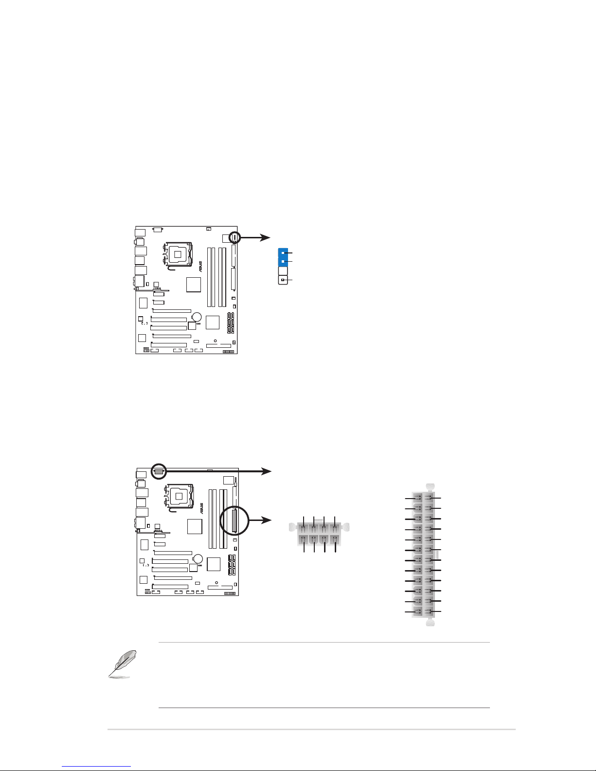
8. ATX power connectors (24-pin EATXPWR, 2x4-pin EATX12V)
These connectors are for ATX power supply plugs. The power supply plugs
are designed to t these connectors in only one orientation. Find the proper
orientation and push down rmly until the connectors completely t.
7. Chassis intrusion connector (4-1 pin CHASSIS)
This connector is for a chassis-mounted intrusion detection sensor or switch.
Connect one end of the chassis intrusion sensor or switch cable to this
connector. The chassis intrusion sensor or switch sends a high-level signal to
this connector when a chassis component is removed or replaced. The signal
is then generated as a chassis intrusion event.
By default , the pin labeled “Chassis Signal” and “Ground” are shorted with
a jumper cap. Remove the jumper caps only when you intend to use the
chassis intrusion detection feature.
P5K DELUXE
®
P5K DELUXE Chassis intrusion connector
CHASSIS
+5VSB_MB
Chassis Signal
GND
(Default)
P5K DELUXE
®
P5K DELUXE ATX power connectors
EATXPWREATX12V
+3 Volts
+3 Volts
Ground
+5 Volts
+5 Volts
Ground
Ground
Power OK
+5V Standby
+12 Volts
-5 Volts
+5 Volts
+3 Volts
-12 Volts
Ground
Ground
Ground
PSON#
Ground
+5 Volts
+12 Volts
+3 Volts
+5 Volts
Ground
GND +12V DC
GND +12V DC
GND +12V DC
GND +12V DC
• Make sure to remove the cap on the EATX12V connector before connecting
an 8-pin EPS +12V power plug.
• Use only either a 4-pin ATX12V or an 8-pin EPS +12V power plug for the
EATX12V connector.
 Loading...