


 R MEW-AM
Socket 370 Intel® 810 microATX Motherboard
USER’S MANUAL

USER'S NOTICE
No part of this manual, including the products and software described in it, may be reproduced, transmitted, transcribed, stored in a retrieval system, or translated into any language in any form or by any means, except documentation kept by the purchaser for backup purposes, without the express written permission of ASUSTeK COMPUTER INC. (“ASUS”).
ASUS PROVIDES THIS MANUAL “AS IS” WITHOUT WARRANTY OF ANY KIND, EITHER EXPRESS OR IMPLIED, INCLUDING BUT NOT LIMITED TO THE IMPLIED WARRANTIES OR CONDITIONS OF MERCHANTABILITY OR FITNESS FOR A PARTICULAR PURPOSE. IN NO EVENT SHALL ASUS, ITS DIRECTORS, OFFICERS, EMPLOYEES OR AGENTS BE LIABLE FOR ANY INDIRECT, SPECIAL, INCIDENTAL, OR CONSEQUENTIAL DAMAGES (INCLUDING DAMAGES FOR LOSS OF PROFITS, LOSS OF BUSINESS, LOSS OF USE OR DATA, INTERRUPTION OF BUSINESS AND THE LIKE), EVEN IF ASUS HAS BEEN ADVISED OF THE POSSIBILITY OF SUCH DAMAGES ARISING FROM ANY DEFECT OR ERROR IN THIS MANUAL OR PRODUCT.
Product warranty or service will not be extended if: (1) the product is repaired, modified or altered, unless such repair, modification of alteration is authorized in writing by ASUS; or (2) the serial number of the product is defaced or missing.
Products and corporate names appearing in this manual may or may not be registered trademarks or copyrights of their respective companies, and are used only for identification or explanation and to the owners’ benefit, without intent to infringe.
•QuickStart and JumperFree are trademarks of ASUSTeK Computer Inc.
•Intel, LANDesk, and Pentium are registered trademarks of Intel Corporation.
•IBM and OS/2 are registered trademarks of International Business Machines.
•Symbios is a registered trademark of Symbios Logic Corporation.
•Windows and MS-DOS are registered trademarks of Microsoft Corporation.
•Adobe and Acrobat are registered trademarks of Adobe Systems Incorporated.
The product name and revision number are both printed on the product itself. Manual revisions are released for each product design represented by the digit before and after the period of the manual revision number. Manual updates are represented by the third digit in the manual revision number.
For previous or updated manuals, BIOS, drivers, or product release information, contact ASUS at http://www.asus.com.tw or through any of the means indicated on the following page.
SPECIFICATIONS AND INFORMATION CONTAINED IN THIS MANUAL ARE FURNISHED FOR INFORMATIONAL USE ONLY, AND ARE SUBJECT TO CHANGE AT ANY TIME WITHOUT NOTICE, AND SHOULD NOT BE CONSTRUED AS A COMMITMENT BY ASUS. ASUS ASSUMES NO RESPONSIBILITY OR LIABILITY FOR ANY ERRORS OR INACCURACIES THAT MAYAPPEAR IN THIS MANUAL, INCLUDING THE PRODUCTS AND SOFTWARE DESCRIBED IN IT.
Copyright © 1999 ASUSTeK COMPUTER INC. All Rights Reserved.
Product Name: |
ASUS MEW-AM |
Manual Revision: |
1.02 E439 |
Release Date: |
October 1999 |
|
|
2 |
ASUS MEW-AM User’s Manual |

ASUS CONTACT INFORMATION
ASUSTeK COMPUTER INC. (Asia-Pacific)
Marketing
Address: |
150 Li-Te Road, Peitou, Taipei, Taiwan 112 |
Telephone: |
+886-2-2894-3447 |
Fax: |
+886-2-2894-3449 |
Email: |
info@asus.com.tw |
Technical Support
MB/Other (tel): English: +886-2-2890-7121
Notebook (tel): English: +886-2-2890-7122
Server (tel): English: +886-2-2890-7123
Fax: +886-2-2895-9254
Email: tsd@asus.com.tw
Newsgroup: news2.asus.com.tw
WWW:www.asus.com.tw
FTP: ftp.asus.com.tw/pub/ASUS
ASUS COMPUTER INTERNATIONAL (America)
Marketing
Address: |
6737 Mowry Avenue, Mowry Business Center, Building 2 |
|
Newark, CA 94560, USA |
Fax: |
+1-510-608-4555 |
Email: |
info-usa@asus.com.tw |
Technical Support
Fax: +1-510-608-4555
BBS: +1-510-739-3774
Email: tsd@asus.com
WWW:www.asus.com
FTP: ftp.asus.com/Pub/ASUS
ASUS COMPUTER GmbH (Europe)
Marketing
Address: |
Harkortstr. 25, 40880 Ratingen, BRD, Germany |
Fax: |
+49-2102-4420-66 |
Email: |
sales@asuscom.de |
Technical Support
Hotline: |
MB/Other: +49-2102-9599-0 |
Notebook: +49-2102-9599-10 |
Fax: |
+49-2102-9599-11 |
|
Online Support: www.asuscom.de/de/support |
|
|
WWW:www.asuscom.de
FTP: ftp.asuscom.de/pub/ASUSCOM
ASUS MEW-AM User’s Manual |
3 |

CONTENTS
1. INTRODUCTION ............................................................................. |
7 |
|
1.1 |
How This Manual Is Organized .................................................. |
7 |
1.2 |
Item Checklist ............................................................................. |
7 |
2. FEATURES ........................................................................................ |
8 |
|
2.1 |
The ASUS MEW-AM Motherboard ........................................... |
8 |
|
2.1.1 Specifications ..................................................................... |
8 |
|
2.1.2 Performance ....................................................................... |
9 |
2.2 |
ASUS MEW-AM Part Definitions ........................................... |
10 |
2.3 |
ASUS MEW-AM Part Locations .............................................. |
11 |
3. HARDWARE SETUP ..................................................................... |
12 |
|
3.1 |
Motherboard Layout ................................................................. |
12 |
3.3 |
Hardware Setup Procedure ....................................................... |
13 |
3.2 |
Layout Contents ........................................................................ |
13 |
3.4 |
Motherboard Settings ................................................................ |
14 |
3.5 |
System Memory (DIMM) ......................................................... |
15 |
|
3.5.1 General DIMM Notes ...................................................... |
15 |
|
3.5.2 DIMM Installation ........................................................... |
16 |
3.6 |
Central Processing Unit (CPU) ................................................. |
17 |
3.7 |
Expansion Cards ....................................................................... |
18 |
|
3.7.1 Expansion Card Installation Procedure ............................ |
18 |
3.8 |
External Connectors .................................................................. |
19 |
3.9 |
Power Connection Procedures .................................................. |
27 |
4. BIOS SETUP .................................................................................... |
28 |
|
4.1 |
Managing and Updating Your BIOS ......................................... |
28 |
|
4.1.1 Upon First Use of the Computer System ......................... |
28 |
|
4.1.2 Updating BIOS Procedures (only when necessary) ......... |
29 |
4.2 |
BIOS Setup Program ................................................................ |
31 |
|
4.2.1 BIOS Menu Bar ............................................................... |
32 |
|
4.2.2 Legend Bar ....................................................................... |
32 |
4.3 |
Main Menu ................................................................................ |
34 |
|
4.3.1 Primary & Secondary Master/Slave ................................ |
35 |
|
4.3.2 Keyboard Features ........................................................... |
38 |
4.4 |
Advanced Menu ........................................................................ |
40 |
|
4.4.1 I/O Device Configuration ................................................ |
42 |
4.5 |
Security Menu ........................................................................... |
43 |
4.6 |
Power Menu .............................................................................. |
45 |
|
4.6.1 General Power Settings .................................................... |
45 |
|
4.6.2 Power-Up Events ............................................................. |
45 |
4.7 |
Boot Menu ................................................................................ |
46 |
|
4.7.1 Boot Sequence ................................................................. |
46 |
4.8 |
Exit Menu ................................................................................. |
47 |
4 |
ASUS MEW-AM User’s Manual |

CONTENTS
5. SOFTWARE SETUP ........................................................................ |
49 |
|
5.1 |
ASUS Smart Motherboard Support CD .................................... |
49 |
|
5.1.2 Support CD Submenus ..................................................... |
50 |
5.2 |
Operating Systems .................................................................... |
52 |
5.3 |
Starting Windows For the First Time ........................................ |
52 |
|
5.3.1 Intel 82802 Firmware Hub Device Found ....................... |
53 |
5.4 |
ASUS LiveUpdate .................................................................... |
54 |
|
5.3.2 PCI Multimedia Audio Device Found ............................. |
55 |
5.5 |
Driver ........................................................................................ |
56 |
|
5.5.1 VGA Driver Setup ........................................................... |
56 |
5.6 |
Other ......................................................................................... |
58 |
|
5.6.1 INF Update Utility for 810 Chipset ................................. |
58 |
|
5.6.2 Intel Security Driver ........................................................ |
59 |
|
5.6.3 YAMAHA S-YXG50 ....................................................... |
60 |
|
5.6.4 YAMAHA XGStudio ....................................................... |
62 |
|
5.6.5 Microsoft DirectX 6.0 Driver .......................................... |
63 |
|
5.6.6 PC-cillin 98 ...................................................................... |
64 |
|
5.6.7 Adobe Acrobat Reader V4.0 ............................................ |
65 |
5.7 |
Uninstalling Programs .............................................................. |
66 |
6. SOFTWARE REFERENCE ............................................................ |
67 |
|
6.1 |
Display Properties ..................................................................... |
67 |
6.2 |
ASUS Update ............................................................................ |
71 |
6.3 |
Using Yamaha XGstudio Player ............................................... |
73 |
|
6.3.1 Yamaha XGstudio Player Control Panel .......................... |
73 |
6.4 |
Using Yamaha XGstudio Mixer ................................................ |
74 |
|
6.4.1 Yamaha XGstudio Mixer Control Panel .......................... |
74 |
6.5 |
Hardware Information ............................................................... |
76 |
7. APPENDIX ........................................................................................ |
77 |
|
7.1 |
PCI-L101 Fast Ethernet Card ................................................... |
77 |
ASUS MEW-AM User’s Manual |
5 |

FCC & DOC COMPLIANCE
Federal Communications Commission Statement
This device complies with FCC Rules Part 15. Operation is subject to the following two conditions:
•This device may not cause harmful interference, and
•This device must accept any interference received, including interference that may cause undesired operation.
This equipment has been tested and found to comply with the limits for a Class B digital device, pursuant to Part 15 of the FCC Rules. These limits are designed to provide reasonable protection against harmful interference in a residential installation. This equipment generates, uses and can radiate radio frequency energy and, if not installed and used in accordance with manufacturer's instructions, may cause harmful interference to radio communications. However, there is no guarantee that interference will not occur in a particular installation. If this equipment does cause harmful interference to radio or television reception, which can be determined by turning the equipment off and on, the user is encouraged to try to correct the interference by one or more of the following measures:
•Re-orient or relocate the receiving antenna.
•Increase the separation between the equipment and receiver.
•Connect the equipment to an outlet on a circuit different from that to which the receiver is connected.
•Consult the dealer or an experienced radio/TV technician for help.
WARNING! Any changes or modifications to this product not expressly approved by the manufacturer could void any assurances of safety or performance and could result in violation of Part 15 of the FCC Rules.
Canadian Department of Communications Statement
This digital apparatus does not exceed the Class B limits for radio noise emissions from digital apparatus set out in the Radio Interference Regulations of the Canadian Department of Communications.
This Class B digital apparatus complies with Canadian ICES-003.
Cet appareil numérique de la classe B est conforme à la norme NMB-003 du Canada.
6 |
ASUS MEW-AM User’s Manual |

1.INTRODUCTION
1.1How This Manual Is Organized
This manual is divided into the following sections:
1) |
INTRODUCTION |
Manual information and checklist |
2) |
FEATURES |
Product information and specifications |
3) HARDWARE SETUP |
Instructions on setting up the motherboard |
|
4) |
BIOS SETUP |
Instructions on setting up the BIOS software |
5) |
SOFTWARE SETUP |
Instructions on setting up the included software |
6) |
SOFTWARE REFERENCE |
Reference material for the included software |
7) |
APPENDIX |
Optional items |
1.2 Item Checklist
Check that your package is complete. If you discover damaged or missing items, please contact your retailer.
(1) ASUS Motherboard
(1) Serial COM2 connector with bracket
(1)80-conductor ribbon cable for internal UltraDMA/66 or UltraDMA/33 IDE drives (NOTE: The 80-conductor cable has a 40-pin connector.)
(1) Ribbon cable for (1) 5.25” and (2) 3.5” floppy disk drives
(1) Bag of spare jumper caps
(1) Support CD with drivers and utilities
(1) This Motherboard User’s Manual
ASUS PCI-L101 Wake-On-LAN 10/100 fast ethernet card (optional)
1.INTRODUCTION |
Sections/Checklist |
|
|
ASUS MEW-AM User’s Manual |
7 |

Specifications |
2.FEATURES |
|
|
2.FEATURES
2.1The ASUS MEW-AM Motherboard
The MEW-AM motherboard from ASUS is designed for the new PC user who wants simple features in a small package.
2.1.1 Specifications
•Latest Intel Socket 370 Processor Support! Supports Intel’s Celeron processor designed for Socket 370 and packaged in Plastic Pin Grid Array (PPGA).
•Latest Intel 810-DC100 Chipset! The 810-DC100 (GMCH+ICH) supports 66/ 100MHz FSB, UltraDMA/66, and 4MB 32-bit 100MHz SDRAM display cache controller.
•Integrated Graphics! Controller supports 3D hyper pipelined architecture, parallel data processing and compression, precise pixel interpolation, full 2D hardware acceleration, and motion video acceleration. Optional onboard 4MB SDRAM display cache allows up to 1024x768x16bit color for 3D graphics and 1600x1200x8bit color for 2D graphics.
•ASUS Graphics Driver! You can gain about 12% performance over that of the standard graphics driver (2D highend graphics WinMark) using ASUS’ custom graphics driver. ASUS custom graphics driver also provides more features and provides selection of higher refresh rates and resolutions.
•Versatile Memory Support! DRAM controller supports asymmetrical addressing and two DIMM sockets support Intel PC100-compliant SDRAMs (16, 32, 64, 128, or 256MB) up to 512MB. (supports a maximum of 4 sides)
•Latest Low Pin Count Multi-I/O: Provides two high-speed UART compatible serial ports and one parallel port with EPP and ECP capabilities.
•Integrated IDE! Controller supports UltraDMA/66 up to 66MB/s, UltraDMA/ 33 up to 33MB/s, and PIO Mode 4 up to 17MB/s.
•Desktop Management Interface (DMI) V2.3! Supports DMI through BIOS, which allows hardware to communicate within a standard protocol creating a higher level of compatibility. (Requires DMI-enabled components.)
•Peripheral Wake-Up! Supports Wake-On-LAN, Wake-On-Ring, and BIOS Wake-Up.
•Firmware Hub! Provides security and other latest power computing features.
•Smart BIOS! 4Mb firmware gives a new easy-to-use interface which provides more control and protection over the motherboard. Provides boot block write protection and HD/SCSI/MO/ZIP/CD/Floppy boot selection. Hardware random number generator supports new security software for data protection and secured Internet transactions.
•Enhanced ACPI & Anti-Boot Virus Protection! Programmable BIOS (Flash EEPROM), offering enhanced ACPI for Windows 98 compatibility, built-in firm- ware-based virus protection, and autodetection of most devices for virtually automatic setup.
8 |
ASUS MEW-AM User’s Manual |

2.FEATURES
•Highest Audio Quality! AC’97 DAC/ADC (software audio) built into the audio codec reduces noise to improve audio quality and performance for a SNR (signal to noise ratio) of +90dB. These features greatly improve voice synthesis and recognition. If more quality is required, an optional onboard Crystal PCI audio improves audio quality beyond software audio.
2.1.2 Performance
•UltraPerformance! Onboard IDE Bus Master controller with two connectors that support four IDE devices in two channels. Supports UltraDMA/66, UltraDMA/33 (IDE DMA Mode 2), PIO Modes 3 & 4, and supports Enhanced IDE devices, such as Tape Backup, CD-ROM, CD-R/RW, and LS-120 drives.
•Dual Speeds! CPU frequency can operate at either 66MHz or 100MHz while system memory operates at either 100MHz or 66MHz. (100MHz CPU with 66MHz SDRAM setting not supported) This asynchronous design can optimize the VGA performance under shared memory configuration. Of course 100MHz/100MHz synchronous host/DRAM clock is recommended for maximum performance.
•Double or Quadruple the IDE Transfer Speed! IDE transfers using UltraDMA/ 33 Bus Master IDE can handle rates up to 33MB/s and up to 66MB/s using UltraDMA/66 technology. The best of all is that these new technology is compatible with existing ATA-2 IDE specifications so there is no need to upgrade current IDE devices or cables.
•Concurrent PCI! Concurrent PCI allows multiple PCI transfers from PCI master buses to memory to CPU.
•SDRAM Optimized Performance! ASUS smart series motherboards support the new generation memory, Synchronous Dynamic Random Access Memory (SDRAM), which increases the data transfer rate to 800MB/s max using PC100 SDRAM.
•ACPI Ready! ACPI (Advanced Configuration and Power Interface) is also implemented on all ASUS smart series motherboards. ACPI provides more Energy Saving Features for future operating systems (OS) supporting OS Direct Power Management (OSPM) functionality. With these features implemented in the OS, PCs can be ready around the clock, yet satisfy all the energy saving standards. To fully utilize the benefits of ACPI, an ACPI-supported OS such as Windows 98 must be used.
•Extreme Graphics! The integrated motion compensation allows for smooth MPEG1 or MPEG2 video playback. Fast 3D graphics engine allows for an exciting gameplay experience.
FEATURES |
Intelligence |
.2 |
|
ASUS MEW-AM User’s Manual |
9 |

2Part
FEATURES .Definitions
2.FEATURES
2.2ASUS MEW-AM Part Definitions
The following are part descriptions for the motherboard parts shown on the next page.
1Socket 370 for Intel Celeron 370 processors
2DIMM Sockets
3ATX Power Connector for connection to an ATX power supply
4Four Mbit Firmware Hub (programmable BIOS)
5Floppy Disk Drive Connector
6Primary and Secondary IDE Connectors
7Low Pin Count Multi-I/O Chipset
8Wake-On-LAN Connector
9Intel I/O Controller Hub (ICH)
10Intel 810-DC100 (GMCH-DC100) Integrated Graphics Chipset
11High-speed 4MB SDRAM for integrated AGP VGA
12Serial COM2 Header
13Four PCI Slots
14Crystal Audio Chipset (optional)
15AC’97 V2.1 Audio CODEC
16Joystick, MIDI, Line Out, Line In, Microphone In Connectors (optional)
17VGA Monitor Output Connector
18Parallel Connector
19Serial COM1 Connector
20USB Connectors
21PS/2 Mouse, PS/2 Keyboard Connectors
10 |
ASUS MEW-AM User’s Manual |

2.FEATURES
2.3ASUS MEW-AM Part Locations
1 |
2 |
3 |
4 |
21
20
19
18
17
16
15
14 13 12 11 |
10 |
9 |
8 |
7 |
6 |
5 |
Part Locations
2. FEATURES
ASUS MEW-AM User’s Manual |
11 |

3.HARDWARE SETUP
3.1Motherboard Layout
Layout Motherboard
H/W .3 SETUP
PS2KBMS
T: Mouse
B: Keyboard
USB
T: Port 1
B: Port 2
COM1 |
PORT |
|
PARALLEL |
PRINTER |
|
VGA
AUDIO |
Line |
|
Out |
||
|
||
_ |
Line |
|
In |
||
GAME |
||
Mic |
||
|
In |
|
|
|
Audio
Codec
CPU_FAN
|
|
Socket 370 |
|
|
168-pin module) |
||||
|
|
|
|
|
|
|
|
|
|
|
|
|
|
|
|
|
|
|
(64/72-bit, |
|
|
|
|
|
|
|
|
|
|
|
|
|
|
|
|
|
|
|
|
|
|
|
|
|
|
|
|
|
Socket 1 |
|
|
|
|
|
Intel 810 |
||||
|
|
|
|
|
DIMM |
||||
CD_IN |
2 MB |
|
Graphics & |
||||||
|
|
SDRAM |
|
|
Memory |
|
|||
|
|
|
|
|
|||||
|
|
|
|
|
|
Controller |
|
||
|
|
|
|
|
|
|
|||
|
|
2 MB |
|
Hub (GMCH) |
|
||||
|
|
SDRAM |
|
|
|
|
|
Row 00 1 |
|
|
|
|
|
|
|
||||
|
|
|
|
|
|
|
|
|
|
PCI Slot 1
MEW-AM
PCI Slot 2
|
PCI Slot 3 |
32-bit PCI |
PCI Slot 4 |
Audio |
|
Chipset |
COM2 |
|
|
|
|
FS4 FS3 FS2 FS1 FS0 |
|
|
|
|
|
External |
|
|
|
|
|
Frequency |
|
|
|
|
|
Selection |
|
|
168-pin module) |
|
|
|
|
|
(64/72-bit, |
|
|
4Mbit |
|
|
|
|
|
Firmware |
|
|
2 |
ConnectorPowerATX |
|
Hub |
|
|
(ATXPWR) |
(FWH) |
|
SECONDARY IDE |
||
DIMM Socket |
|
||||
|
|
|
|
||
|
|
|
|
|
|
|
|
|
Super I/O |
|
|
2 |
3 |
|
|
|
|
|
|
|
IDE |
|
FLOPPY |
Intel I/O |
|
PRIMARY |
|
||
Controller |
|
|
|
|
|
Hub (ICH) |
|
|
|
|
|
|
|
|
CR2032 3V |
|
|
|
|
|
Lithium Cell |
|
|
|
|
CMOS Power |
|
|
|
RTCLR |
|
WOL_CON |
PANEL |
||
(Grayed items are optional at the time of purchase.)
12 |
ASUS MEW-AM User’s Manual |

3.HARDWARE SETUP
3.2Layout Contents
Motherboard Settings
1) FS0, FS1, FS2, FS3, FS4 p.14 CPU External Clock (BUS) Frequency Setting
Expansion Slots
1) |
DIMM1, DIMM2 |
p.15 |
168-Pin DIMM Memory Support |
2) |
Socket 370 |
p.17 |
Central Processing Unit (CPU) Socket |
3) |
PCI1, PCI2, PCI3, PCI4 |
p.18 |
32-bit PCI Bus Expansion Slots |
Connectors
1) |
PS2KBMS |
p.19 |
PS/2 Mouse Connector (6-pin female) |
2) |
PS2KBMS |
p.19 |
PS/2 Keyboard Connector (6-pin female) |
3) |
USB |
p.20 |
Universal Serial Bus Ports 1 & 2 (Two 4-pin female) |
4) |
PRINTER |
p.20 |
Parallel Port Connector (25-pin female) |
5) |
COM1 |
p.20 |
Serial Port COM1 Connector (9-pin male) |
6) |
VGA |
p.21 |
Monitor (VGA) Output Connector (15-pin female) |
7) |
GAME_AUDIO |
p.21 |
Joystick/MIDI Connector (15-pin female) (optional) |
8) |
GAME_AUDIO |
p.21 |
Audio Port Connectors (Three 1/8” female) (optional) |
9) |
PRIMARY/SECONDARY IDE |
p.22 |
Primary/Secondary IDE Connectors (Two 40-1pins) |
10) |
FLOPPY |
p.22 |
Floppy Disk Drive Connector (34-1pins) |
11) |
WOL_CON |
p.23 |
Wake-On-LAN Connector (3 pins) |
12) |
COM2 |
p.23 |
Serial Port COM2 Header (10-1 pins) |
13) |
CPU_FAN, CHA_FAN |
p.24 |
CPU and Chassis Fan Connectors (3 pins) |
14) |
LED (PANEL) |
p.25 |
System Message LED (2 pins) |
15) |
KEYLOCK (PANEL) |
p.25 |
Keyboard Lock Switch Lead (2 pins) |
16) |
EXSMI (PANEL) |
p.25 |
System Management Interrupt Switch Lead (2 pins) |
17) |
SPEAKER (PANEL) |
p.25 |
System Warning Speaker Connector (4 pins) |
18) |
PWRSW (PANEL) |
p.25 |
ATX Power / Soft-Off Switch Lead (2 pins) |
19) |
HDLED (PANEL) |
p.25 |
IDE Activity LED (2 pins) |
20) |
PLED (PANEL) |
p.25 |
System Power LED Lead (3-1 pins) |
21) |
RESET (PANEL) |
p.25 |
Reset Switch Lead (2 pins) |
22) |
CD_IN |
p.26 |
Internal Audio Connector (4-pins) (optional) |
23) |
ATXPWR |
p.26 |
ATX Power Supply Connector (20 pins) |
3.3 Hardware Setup Procedure
Before using your computer, you must complete the following steps:
•Check Motherboard Settings
•Install Memory Modules
•Install the Central Processing Unit (CPU)
•Install Expansion Cards
•Connect Ribbon Cables, Panel Wires, and Power Supply
Layout Contents
3. H/W SETUP
ASUS MEW-AM User’s Manual |
13 |

Memory System
H/W .3 SETUP
3.HARDWARE SETUP
3.4Motherboard Settings
WARNING! Computer motherboards and expansion cards contain very delicate Integrated Circuit (IC) chips. To protect them against damage from static electricity, you should follow some precautions whenever you work on your computer.
1.Unplug your computer when working on the inside.
2.Use a grounded wrist strap before handling computer components. If you do not have one, touch both of your hands to a safely grounded object or to a metal object, such as the power supply case.
3.Hold components by the edges and try not to touch the IC chips, leads or connectors, or other components.
4.Place components on a grounded antistatic pad or on the bag that came with the component whenever the components are separated from the system.
1)CPU External Frequency Setting (FS0, FS1, FS2, FS3, FS4)
Current PCI bus is limited to 33MHz, Socket 370 Celeron processors limited to 66MHz, and SDRAM limited to the DIMM type 66/100/133MHz. (66MHz SDRAM is not supported on this motherboard.) Other settings are for experienced users only.
Recommended
CPU Setting
NOTE: For updated processor settings, please visit ASUS’ web site (see ASUS CONTACT INFORMATION)
WARNING! CPU frequencies above 66MHz exceed the specifications for current Celeron processors and are not guaranteed to be stable. Premature wearing of the processor may result when overclocking. Be sure that the DIMM you use can handle the specified SDRAM MHz or else bootup will not be possible.
14 |
ASUS MEW-AM User’s Manual |

3.HARDWARE SETUP
3.5System Memory (DIMM)
NOTE: No hardware or BIOS setup is required after adding or removing memory.
This motherboard uses only Dual Inline Memory Modules (DIMMs). Sockets are available for 3.3Volt (power level) unbuffered Synchronous Dynamic Random Access Memory (SDRAM).
This chipset does not support ECC. However, ECC memory modules may still be used, but the ECC function will not be available.
Install memory in any combination as follows:
Location |
168-pin DIMM SDRAM |
|
Total Memory |
DIMM1 |
Single-Sided/Double-Sided |
x1 |
|
(Rows 0&1) |
16, 32, 64, 128MB, or 256MB |
|
|
DIMM2 |
Single-Sided/Double-Sided |
x1 |
|
(Rows 2&3) |
16, 32, 64, 128MB, or 256MB |
|
|
|
|
|
|
|
Total System Memory (Max 512MB) |
= |
|
|
|
|
|
NOTE: At the time this User’s Manual was written, 256MB DIMMs are only available as Double-Sided registered memory (128Mbit cells). Using 2x2x2 SDRAM can greatly improve the onboard graphics’ performance.
3.5.1 General DIMM Notes
•This motherboard operates at 100MHz, therefore PC100-compliant modules must be used because of the strict timing issues involved under this speed.
•ASUS motherboards support SPD (Serial Presence Detect) DIMMs. This is the memory of choice for best performance vs. stability.
•SDRAM chips are generally thinner with higher pin density than EDO (Extended Data Output) chips.
•BIOS shows SDRAM memory on bootup screen.
•Single-sided DIMMs come in 16, 32, 64,128MB; double-sided come in 32, 64, 128, 256MB.
.3 SETUPH/W
System Memory
ASUS MEW-AM User’s Manual |
15 |

SETUP H/W .3 CPU
3.HARDWARE SETUP
3.5.2DIMM Installation
Insert the module(s) as shown. Because the number of pins are different on either side of the breaks, the module will only fit in the orientation shown. DIMM modules are longer and have different pin contact on each side and therefore have a higher pin density. SIMMs have the same pin contact on both sides.
Lock
88 Pins
FRONT
1
MEW-AM
60 Pins
20 Pins
MEW-AM 168-Pin DIMM Sockets
The DIMMs must be 3.3V Unbuffered for this motherboard. To determine the DIMM type, check the notches on the DIMMs (see figure below).
168-Pin DIMM Notch Key Definitions (3.3V)
|
|
|
|
|
|
|
|
|
|
|
|
|
|
|
|
|
|
|
|
|
|
|
|
|
|
|
|
|
|
DRAM Key Position |
Voltage Key Position |
|||
RFU |
Unbuffered |
5.0V |
Reserved |
Buffered |
|
3.3V |
|
The notches on the DIMM will shift between left, center, or right to identify the type and also to prevent the wrong type from being inserted into the DIMM slot on the motherboard. You must ask your retailer the correct DIMM type before purchasing. This motherboard supports four clock signals per DIMM slot.
16 |
ASUS MEW-AM User’s Manual |
3.HARDWARE SETUP
3.6Central Processing Unit (CPU)
The motherboard provides a ZIF Socket 370. The CPU that came with the motherboard should have a fan attached to it to prevent overheating. If this is not the case, then purchase a fan before you turn on your system.
WARNING! Be sure that there is sufficient air circulation across the processor’s heatsink by regularly checking that your CPU fan is working. Without sufficient circulation, the processor could overheat and damage both the processor and the motherboard. You may install an auxiliary fan, if necessary.
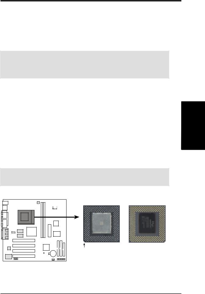
To install a CPU, first turn off your system and remove its cover. Locate the ZIF socket and open it by first pulling the lever sideways away from the socket then upwards to a 90-degree angle. Insert the CPU with the correct orientation as shown. The notched corner should point towards the end of the lever. Because the CPU has a corner pin for two of the four corners, the CPU will only fit in the orientation as shown. The picture is for reference only; you should have a CPU fan that covers the face of the CPU. With the added weight of the CPU fan, no force is required to insert the CPU. Once completely inserted, close the socket’s lever while holding down the CPU.
NOTE: Do not forget to set the correct Bus Frequency and Multiple (frequency multiple setting is available only on unlocked processors) for your Socket 370 processor or else boot-up may not be possible.
CAUTION! Be careful not to scrape the motherboard when mounting a clampstyle processor fan or else damage may occur to the motherboard.
Socket 370 CPU (Top) Socket 370 CPU (Bottom)
1
MEW-AM
Notch
MEW-AM Socket 370
.3 SETUPH/W
Expansion Cards
ASUS MEW-AM User’s Manual |
17 |
SETUP H/W .3
Cards Expansion
3.HARDWARE SETUP
3.7Expansion Cards
WARNING! Make sure that you unplug your power supply when adding or removing expansion cards or other system components. Failure to do so may cause severe damage to both your motherboard and expansion cards.
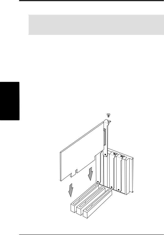
3.7.1 Expansion Card Installation Procedure
1.Read the documentation for your expansion card and make any necessary hardware or software settings for your expansion card, such as jumpers or switches.
2.Remove your computer system’s cover and the bracket plate with screw on the slot you intend to use. Keep the bracket for possible future use.
3.Carefully align the card’s connectors and press firmly.
4.Secure the card on the slot with the screw you removed above.
5.Replace the computer system’s cover.
6.Set up the BIOS if necessary.
7.Install the necessary software drivers for your expansion card.
18 |
ASUS MEW-AM User’s Manual |
3.HARDWARE SETUP
3.8External Connectors
WARNING! Some pins are used for connectors or power sources. These are clearly distinguished from jumpers in the Motherboard Layout. Placing jumper caps over these connector pins will cause damage to your motherboard.
IMPORTANT: Ribbon cables should always be connected with the red stripe to Pin 1 on the connectors. Pin 1 is usually on the side closest to the power connector on hard drives and CD-ROM drives, but may be on the opposite side on floppy disk drives. Check the connectors before installation because there may be exceptions. Look on IDE ribbon cable must be less than 46 cm (18 in.), with the second drive connector no more than 15 cm (6 in.) from the first connector.
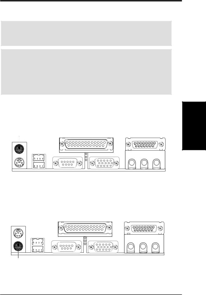
1)PS/2 Mouse Connector (6-pin PS2KBMS)
The system will direct IRQ12 to the PS/2 mouse if one is detected. If one is not detected, expansion cards can use IRQ12.
PS/2 Mouse (6-pin Female)
2)PS/2 Keyboard Connector (6-pin PS2KBMS)
This connection is for a standard keyboard using an PS/2 plug (mini DIN). This connector will not allow standard AT size (large DIN) keyboard plugs. You may use a DIN to mini DIN adapter on standard AT keyboards.
Connectors
3. H/W SETUP
PS/2 Keyboard (6-pin Female)
ASUS MEW-AM User’s Manual |
19 |

3.HARDWARE SETUP
3)Universal Serial Bus Ports (Two 4-pin USB)
Two USB ports are available for connecting USB devices.
USB 1
SETUP H/W .3
Connectors
Universal Serial Bus (USB) 2
4)Parallel Port Connector (25-pin PRINTER)
The parallel connector is used for a single parallel device such as a printer or a portable drive. See Parallel Port in 4.4.1 I/O Device Configuration for settings.
NOTE: Serial printers must be connected to the serial port.
Parallel (Printer) Port (25-pin Female)
5)Serial Port Connector (9-pin COM1)
One serial port is ready for a mouse or other serial devices. A second serial port is available using a serial port bracket connected from the motherboard to an expansion slot opening. See Serial Port A or B in 4.4.1 I/O Device Configuration for settings.
Serial Port (9-pin Male) COM 1
20 |
ASUS MEW-AM User’s Manual |
3.HARDWARE SETUP
6)Monitor Output Connector (15-pin VGA)
This connector is for output to a VGA-compatible device.
VGA Monitor (15-pin Female)
7)Joystick/MIDI Connector (15-pin GAME_AUDIO) (optional)
You may connect game joysticks or game pads to this connector for playing games. Connect MIDI devices for playing or editing professional audio.
Joystick/Midi (15-pin Female)
NOTE: The onboard game port is to be used only if you are not using any PCI or ISA audio card with a game port.
8)Audio Port Connectors (Three 1/8” GAME_AUDIO) (optional)
Line Out (lime) can be connected to headphones or preferably powered speakers. Line In (light blue) allows tape players or other audio sources to be recorded by your computer or played through the Line Out (lime). Mic (pink) allows microphones to be connected for inputting voice.
Connectors
3. H/W SETUP
Line Out Line In Mic
1/8" Stereo Audio Connectors
ASUS MEW-AM User’s Manual |
21 |
SETUP H/W .3
Connectors
3.HARDWARE SETUP
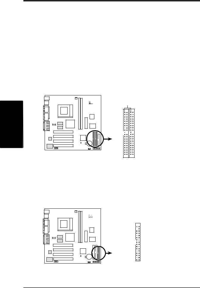
9)Primary / Secondary IDE Connectors (Two 40-1pin IDE)
These connectors support the provided IDE hard disk ribbon cable. After connecting the single end to the board, connect the two plugs at the other end to your hard disk(s). If you install two hard disks, you must configure the second drive to Slave mode by setting its jumper accordingly. Please refer to your hard disk documentation for the jumper settings. (Pin 20 is removed to prevent inserting in the wrong orientation when using ribbon cables with pin 20 plugged).
TIP: You may configure two hard disks to be both Masters with two ribbon cables – one for the primary IDE connector and another for the secondary IDE connector and select the boot disk through Boot Sequence in 4.7 Boot Menu.
IMPORTANT: UltraDMA/66 IDE devices must use an 80-wire IDE cable or else devices will automatically be limited to UltraDMA/33 mode.
1
MEW-AM
MEW-AM IDE Connectors
|
PIN 1 |
Primary IDE Connector |
Secondary IDE Connector |
NOTE: Orient the red markings on the IDE ribbon cable to PIN 1
10)Floppy Disk Drive Connector (34-1pin FLOPPY)
This connector supports the provided floppy drive ribbon cable. After connecting the single end to the board, connect the two plugs on the other end to the floppy drives. (Pin 5 is removed to prevent inserting in the wrong orientation when using ribbon cables with pin 5 plugged).
NOTE: Orient the red markings on the floppy ribbon cable to PIN 1
PIN 1


1
MEW-AM
MEW-AM Floppy Disk Drive Connector
22 |
ASUS MEW-AM User’s Manual |

3.HARDWARE SETUP
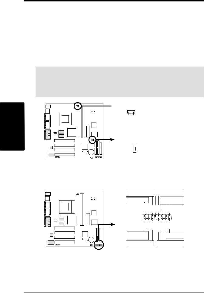
11)Wake-On-LAN Connector (3-pin WOL_CON)
This connector connects to a LAN card with a Wake-On-LAN output, such as the ASUS PCI-L101 Ethernet card. The connector powers up the system when a wakeup packet or signal is received through the LAN card.
IMPORTANT: This feature requires that your system has an ATX power supply with at least 720mA +5V standby power.
IMPORTANT: Requires an ATX power supply with at least 720mA +5 volt standby power
+5 Volt Standby PME
1
MEW-AM
Ground
MEW-AM Wake-On-LAN Connector
12)Serial Port Header (10-1 pin COM2)
The optional serial port bracket can be used to add an additional serial port for additional serial devices.
1 |
MEW-AM |

 to COM2 Header Pin 1
MEW-AM Serial COM2 Bracket
Connectors
3. H/W SETUP
ASUS MEW-AM User’s Manual |
23 |
SETUP H/W .3
Connectors
3.HARDWARE SETUP
13)CPU Fan Connectors (3-pin CPU_FAN)
This connector supports a cooling fan of 350mA (4.2 Watts) or less. Orientate the fan so that the heat sink fins allow airflow to go across the onboard heat sink(s) instead of the expansion slots. Depending on the fan manufacturer, the wiring and plug may be different. The red wire should be positive, while the black should be ground. Connect the fan’s plug to the board taking into consideration the polarity of the connector.
NOTE: The “Rotation” signal cannot be monitored on this motherboard.
WARNING! The CPU and/or motherboard will overheat if there is no airflow across the CPU and onboard heatsinks. Damage may occur to the motherboard and/or the CPU fan if these pins are incorrectly used. These are not jumpers, do not place jumper caps over these pins.
 CPU Fan Power
Rotation+12VGND
1
Chassis Fan Power
MEW-AM
+12V 
 GND
GND 

MEW-AM 12-Volt Cooling Fan Power
The following PANEL illustration is used for items 14-21
|
|
Keyboard Lock |
ExternalSMILead |
|||
|
|
MessageLED |
|
|
|
Speaker |
|
|
|
|
|
Connector |
|
|
|
MSGLED+ MSGLED- |
|
|
|
|
|
|
Keylock |
Ground |
ExtSMI# Ground +5V |
Ground Speaker |
|
|
1 |
PWRBTN Ground |
IDELED- |
IDELED+ |
PWRLED+ PWRLED- |
PWRLEDReset Ground |
MEW-AM |
|
|
|
|
|
|
|
|
ATX Power |
|
|
|
Reset SW |
|
|
Switch* |
|
|
|
|
|
|
|
|
|
|
|
|
|
HDLED |
|
|
Power LED |
|
* Requires an ATX power supply.
MEW-AM System Panel Connectors
24 |
ASUS MEW-AM User’s Manual |
 Loading...