


 Loading...
J3455T-IM-A N3350T-IM-A N4200T-IM-A
<![endif]>Industrial Motherboard

E17325
First Edition
November 2020
Copyright © 2020 ASUSTeK COMPUTER INC. All Rights Reserved.
No part of this manual, including the products and software described in it, may be reproduced, transmitted, transcribed, stored in a retrieval system, or translated into any language in any form or by any means, except documentation kept by the purchaser for backup purposes, without the express written permission of ASUSTeK COMPUTER INC. (“ASUS”).
Product warranty or service will not be extended if: (1) the product is repaired, modified or altered, unless such repair, modification of alteration is authorized in writing by ASUS; or (2) the serial number of the product is defaced or missing.
ASUS PROVIDES THIS MANUAL “AS IS” WITHOUT WARRANTY OF ANY KIND, EITHER EXPRESS OR IMPLIED, INCLUDING BUT NOT LIMITED TO THE IMPLIED WARRANTIES OR CONDITIONS OF MERCHANTABILITY OR FITNESS FOR A PARTICULAR PURPOSE. IN NO EVENT SHALL ASUS, ITS DIRECTORS, OFFICERS, EMPLOYEES OR AGENTS BE LIABLE FOR ANY INDIRECT, SPECIAL, INCIDENTAL, OR CONSEQUENTIAL DAMAGES (INCLUDING DAMAGES FOR LOSS OF PROFITS, LOSS OF BUSINESS, LOSS OF USE OR DATA, INTERRUPTION OF BUSINESS AND THE LIKE), EVEN IF ASUS HAS BEEN ADVISED OF THE POSSIBILITY OF SUCH DAMAGES ARISING FROM ANY DEFECT OR ERROR IN THIS MANUAL OR PRODUCT.
SPECIFICATIONS AND INFORMATION CONTAINED IN THIS MANUAL ARE FURNISHED FOR INFORMATIONAL USE ONLY, AND ARE SUBJECT TO CHANGE AT ANY TIME WITHOUT NOTICE, AND SHOULD NOT BE CONSTRUED AS A COMMITMENT BY ASUS. ASUS ASSUMES NO RESPONSIBILITY OR LIABILITY FOR ANY ERRORS OR INACCURACIES THAT MAY APPEAR IN THIS MANUAL, INCLUDING THE PRODUCTS AND SOFTWARE DESCRIBED IN IT.
Products and corporate names appearing in this manual may or may not be registered trademarks or copyrights of their respective companies, and are used only for identification or explanation and to the owners’ benefit, without intent to infringe.
ii

Contents
Chapter 1 |
Product overview |
|
|
1.1 |
Package contents......................................................................... |
1-1 |
|
1.2 |
Features |
......................................................................................... |
1-1 |
1.3 |
Specifications............................................................................... |
1-2 |
|
Chapter 2 |
Motherboard information |
|
|
2.1 |
Before you proceed...................................................................... |
2-1 |
|
2.2 |
Motherboard layout...................................................................... |
2-2 |
|
2.3 |
Central Processing Unit (CPU).................................................... |
2-4 |
|
2.4 |
System memory............................................................................ |
2-5 |
|
2.5 |
Jumpers |
......................................................................................... |
2-6 |
2.6 |
Connectors.................................................................................. |
2-10 |
|
|
2.6.1 .................................................. |
Rear panel connectors |
2-10 |
|
2.6.2 ........................................................ |
Internal connectors |
2-11 |
Chapter 3 |
BIOS setup |
|
|
3.1 |
BIOS setup program..................................................................... |
3-1 |
|
|
3.1.1 |
BIOS menu screen.......................................................... |
3-2 |
3.2 |
Main menu..................................................................................... |
3-2 |
|
|
3.2.1 |
System Date [Day MM/DD/YYYY]................................... |
3-2 |
|
3.2.2 |
System Time [HH:MM:SS]............................................... |
3-2 |
3.3 |
Advanced menu............................................................................ |
3-3 |
|
|
3.3.1 |
Platform Trust Technology.............................................. |
3-3 |
|
3.3.2 |
Trusted Computing.......................................................... |
3-3 |
|
3.3.3 |
CPU Configuration........................................................... |
3-3 |
|
3.3.4 |
Graphic Configuration...................................................... |
3-4 |
|
3.3.5 |
PCI Express Configuration.............................................. |
3-6 |
|
3.3.6 |
CSM Configuration.......................................................... |
3-7 |
|
3.3.7 |
Super IO Configuration.................................................... |
3-7 |
|
3.3.8 |
Serial Console Redirection.............................................. |
3-7 |
|
3.3.9 |
SATA Configuration......................................................... |
3-8 |
|
3.3.10 |
Network Stack Configuration........................................... |
3-8 |
|
3.3.11 |
USB Configuration........................................................... |
3-8 |
|
3.3.12 |
Onboard Devices Configuration...................................... |
3-9 |
|
3.3.13 |
Watchdog Timer............................................................ |
3-10 |
|
3.3.14 |
APM Configuration........................................................ |
3-10 |
iii

|
3.3.15 |
EZ-Flash........................................................................ |
3-10 |
|
3.3.16 |
Miscellaneous................................................................ |
3-10 |
3.4 |
Hardware Monitor menu............................................................. |
3-11 |
|
3.5 |
Security menu............................................................................. |
3-11 |
|
3.6 |
Boot menu................................................................................... |
3-13 |
|
|
Boot Configuration........................................................................ |
3-13 |
|
|
FIXED BOOT ORDER Priorities .................................................. |
3-13 |
|
3.7 |
Exit menu..................................................................................... |
3-13 |
|
|
Save Changes & Exit.................................................................... |
3-13 |
|
|
Discard Changes & Exit................................................................ |
3-14 |
|
|
Save Changes & Reset................................................................ |
3-14 |
|
|
Discard Changes & Reset............................................................ |
3-14 |
|
|
Save changes............................................................................... |
3-14 |
|
|
Discard changes........................................................................... |
3-14 |
|
|
Restore Defaults........................................................................... |
3-14 |
|
|
Save as User Defaults.................................................................. |
3-14 |
|
|
Restore User Defaults.................................................................. |
3-14 |
|
Appendix
Notices....................................................................................................... |
A-1 |
ASUS contact information........................................................................ |
A-5 |
iv
Chapter 1
Product overview
1.1Package contents
Check your industrial motherboard package for the following items.
1 x ASUS J3455T-IM-A/N3350T-IM-A/N4200T-IM-A Motherboard
1 x SATA 6.0 Gb/s cable
1 x SATA power cable
2 x M.2 screw packages 1 x ASUS I/O Shield
NOTE: If any of the above items is damaged or missing, contact your distributor or sales representative immediately.
1.2Features
•Built-in Intel® Celeron® Quad-core Processor J3455/N3350/N4200
•Two DDR3L 1866/1600/1333 MHz Non-ECC Un-buffered SO-DIMMs up to 8GB
•2 x SATA 6Gb/s, 4 x USB 3.2 Gen 1, 2 x USB 2.0, 6 x COM headers
•1 x PCIe 2.0 x1 slot (colay with M.2 E Key), 1 x Full/Half-size PCIe mini card slot (w/SIM holder), 1 x M.2 Socket 1 with E key
•Multi-display: 1 x VGA, 1 x HDMI, 1 x DisplayPort++, 1 x LVDS, 1 x Embedded DisplayPort (BOM colay with LVDS,optional), HDMI + VGA + LVDS, VGA+HDMI+eDP, DP+HDMI+LVDS, DP+HDMI+eDP
Chapter 1: General information |
1-1 |

1.3Specifications
CPU |
Built-in Intel® Celeron® Quad-core Processor J3455/N3350/N4200 |
|
Memory |
2 x DDR3L, max.8GB, DDR3L 1866/1600/1333 MHz Non-ECC, |
|
Unbuffered Memory |
||
|
||
|
Integrated graphics processor - Intel® HD Graphics support |
|
|
- Supports VGA output with a maximum resolution of 1920 x |
|
|
1200 @ 60Hz (colay with DisplayPort++) |
|
|
- Supports HDMITM output with a maximum resolution of 3840 |
|
|
x 2160 @ 30Hz |
|
Graphics |
- Supports DisplayPort++ output with a maximum resolution of |
|
4096 x 2160 @ 30Hz |
||
|
||
|
- Supports LVDS output with a maximum resolution of 1920 x |
|
|
1200 @ 60Hz |
|
|
- Supports Embedded DisplayPort output with a maximum |
|
|
resolution of 4096 x 2160 @ 30Hz |
|
|
Supports up to three displays simultaneously |
|
|
1 x PCI Express 2.0 x1 slot (colay with M.2 E Key) |
|
Expansion slots |
1 x Full/Half-size PCIe minicard slot (w/SIM holder) |
|
1 x M.2 Socket 1 with E key, type 2230 for WIFI/BT device (colay |
||
|
||
|
with PCIe) |
|
Storage |
2 x SATA Gen3.0 up to 6.0 Gb/s ports |
|
1 x Full/Half-size mSATA slot (shared with Mini PCIe) |
||
|
||
Ethernet |
2 x Realtek® 8111H, supports WOL/PXE |
|
Audio |
Realtek® ALC887 High Definition Audio |
|
|
1 x VGA port |
|
|
1 x HDMITM port |
|
|
1 x DisplayPort++ |
|
Rear panel I/O |
4 x USB 3.2 Gen 1 ports |
|
ports |
2 x LAN (RJ45) ports |
|
|
1 x P/S2 keyboard header |
|
|
1 x Audio jack |
|
|
1 x DC-IN jack |
|
|
6 x Serial Port headers (5 x RS232, 1 x RS232/422/485) |
|
|
1 x CPU Fan header (PWM Mode) |
|
|
1 x Chassis Fan header (PWM Mode) |
|
Internal |
1 x Chassis intrusion header |
|
Connectors |
1 x Front panel audio header (AAFP) |
|
|
1 x System panel header (10-1 pin) |
|
|
1 x Clear CMOS jumper |
|
|
1 x LVDS header |
|
|
(continued on the next page) |
1-2 |
J3455T-IM-A/N3350T-IM-A/N4200T-IM-A |

|
|
|
2 x USB 2.0 headers support additional 4 USB 2.0 ports |
|
|
|
|
1 x 8-bit GPIO header |
|
|
|
|
1 x LPC debug header |
|
|
|
|
1 x 3-pin ATX power connector (5VSB) |
|
|
|
|
1 x 4-pin ATX 12V power connector |
|
|
|
|
1 x SATA power connector |
|
|
|
|
2 x SATA ports |
|
|
|
|
1 x Keyboard/Mouse header |
|
Internal |
|
1 x Speaker header |
||
Connectors |
|
1 x eDP connector (optional) |
||
|
|
|
1 x I2C header |
|
|
|
|
1 x SPI TPM header |
|
|
|
|
1 x WDT header |
|
|
|
|
1 x AT/ATX selection header |
|
|
|
|
1 x Flat Panel Display Brightness selection header |
|
|
|
|
1 x Display Panel Backlight Power Selector |
|
|
|
|
1 x Display Panel VCC Power Selector |
|
|
|
|
1 x LCD panel monitor switch header |
|
Manageability |
|
WfM 2.0, WOL by PME |
||
Power |
|
AT/ATX mode and DC-IN (12V) |
||
requirement |
|
|||
|
|
|
||
Operation |
|
0~60°C |
||
Temperature |
|
|||
|
|
|
||
Non-Operation |
|
-40~85°C |
||
Temperature |
|
|||
|
|
|
||
Relative Humidity |
|
0%~85% |
|
|
OS support |
|
Windows® 10 (64bit) / Windows® 10 IoT Enterprise |
||
|
Ubuntu, RedHat Enterprise, Fedora Workstation, OpenSUSE |
|||
|
|
|
||
Form Factor |
|
Thin Mini-ITX Form Factor, 6.7”x 6.7” (17.0cm x 17.0cm) |
||
|
|
|
|
|
|
NOTE: |
Specifications are subject to change without notice. |
||
|
|
|
|
|
Chapter 1: General information |
1-3 |
Chapter 2
Motherboard information
2.1Before you proceed
Take note of the following precautions before you install motherboard components or change any motherboard settings.
CAUTION!
•Unplug the power cord from the wall socket before touching any component.
•Before handling components, use a grounded wrist strap or touch a safely grounded object or a metal object, such as the power supply case, to avoid damaging them due to static electricity.
•Hold components by the edges to avoid touching the ICs on them.
•Whenever you uninstall any component, place it on a grounded antistatic pad or in the bag that came with the component.
•Before you install or remove any component, always remove the AC power by unplugging the power cord from the power outlet. Failure to do so may cause severe damage to the motherboard, peripherals, or components.
Chapter 2: Motherboard information |
2-1 |

2.2Motherboard layout
NOTE: Place four screws into the holes indicated by circles to secure the motherboard to the chassis.
CAUTION! Do not overtighten the screws! Doing so can damage the motherboard.
Place this side towards the rear of the chassis
31
30
29
28
27
1 |
2 3 4 5 6 7 8 9 2 |
||
|
17.0cm(6.7in) |
|
|
|
|
|
|
|
WDT_EN |
|
I2C |
|
|
|
|
DC_PWR |
CPU_FAN |
|
ATX_5VSB |
ATX12V |
CLRTC |
CHA_FAN |
|
|
<![if ! IE]> <![endif]>KBMS CON |
||
AT_ATX_SEL |
|||
|
|
|
|
VGA |
|
|
|
|
LPC_DEBUG |
|
|
|
|
U32G1_12 |
8Mb |
|
<![if ! IE]> <![endif]>-pin module) |
<![if ! IE]> <![endif]>-pin module) |
|
BIOS |
Intel® |
<![if ! IE]> <![endif]>204 |
<![if ! IE]> <![endif]>204 |
|
|
HDMI |
|
<![if ! IE]> <![endif]>A-IM-J3455T |
|||
SPI_TPM |
J3455/ |
<![if ! IE]> <![endif]>(64bit,B1DIMM-SoDDR3L |
<![if ! IE]> <![endif]>(64bit,A1DIMM-SoDDR3L |
||
|
|
N3350/ |
|
|
|
U32G1_34 |
|
N4200 |
|
|
|
|
SoC |
|
|
|
|
|
|
|
|
|
DP |
|
PANEL_SW |
COM6 |
COM5 |
COM4 |
COM3 |
COM2 |
COM1 |
|
|
<![if ! IE]> <![endif]>SEL |
|
|
|
|
|
|
|
|||||||||
|
|
|
|
|
|
|
|
|
|
|
|
<![if ! IE]> <![endif]>_ |
|
|
|
|
NANO_SIM |
|
|
|
|
|
<![if ! IE]> <![endif]>MPCIE MSATA USBE34 |
<![if ! IE]> <![endif]>SATA6G 2 USBE12 |
|
<![if ! IE]> <![endif]>COM1 |
|
LAN1_LAN2 |
Realtek® |
|
|
|
|
|
|
|
<![if ! IE]> <![endif]>SPEAKER SATA PWRCON |
|
|||
8111H |
|
|
|
|
|
|
|
|
|||||
|
|
Realtek® |
|
<![if ! IE]> <![endif]>M.2(WIFI) |
|
Super |
<![if ! IE]> <![endif]>SATA6G 1 |
|
|||||
|
|
|
|
I/O |
|
||||||||
|
|
8111H |
|
|
|
||||||||
AUDIO |
ALC |
|
|
|
|
|
<![if ! IE]> <![endif]>CHASSIS |
||||||
887 |
|
|
|
|
|
||||||||
|
|
BATTERY |
|
|
|
|
|||||||
|
|
|
|
|
|
|
|
VCC_PWR_SEL |
|
|
|
||
|
|
|
PCIEX1 |
|
|
|
|
LCD_BLKT_PANEL |
F_PANEL |
|
|
||
|
AAFP |
|
GPIO_CON |
LVDS_EDP |
|
BKLPWR_SEL |
|
|
|||||
|
|
|
|
|
|
|
|
||||||
|
26 |
25 |
|
24 |
23 |
22 |
21 20 19 18 17 16 |
|
|||||
10
<![if ! IE]><![endif]>17.0cm(6.7in)
11
12
13
14
15
2-2 |
J3455T-IM-A/N3350T-IM-A/N4200T-IM-A |

Connectors/Jumpers/Slots |
Page |
|
1. |
ATX Power connector (4-pin ATX12V) |
2-11 |
2. |
CPU and Chassis fan headers (4-pin CPU_FAN, 4-pin CHA_FAN) |
2-11 |
3. |
WDT Enbale jumper (2-pin WDT_EN) |
2-7 |
4. |
Clear RTC RAM (2-pin CLRTC) |
2-6 |
5. |
AT/ATX mode selection (3-pin AT_ATX_SEL) |
2-7 |
6. |
Built-in Intel® Celeron® Quad-core Processor J3455/N3350/N4200 |
2-4 |
7. |
ATX 5V Standby Power header (3-pin ATX_5VSB) |
2-12 |
8. |
DDR3L SO-DIMM slots |
2-5 |
9. |
I2C header (6-1 pin I2C) |
2-12 |
10. |
PS/2 Keyboard and Mouse header (8-pin KBMS_CON) |
2-13 |
11. |
USB 2.0 headers (10-1pin USB_E12, USB_E34) |
2-13 |
12. |
COM RING/+5V/+12V selection (6-pin COM1_SEL) |
2-8 |
13. |
SATA Power connector (SATA_PWRCON) |
2-14 |
14. |
SATA 6.0 Gb/s ports (7-pin SATA6G_1/2) |
2-14 |
15. |
Chassis Intrusion header (4-pin CHASSIS) |
2-8 |
16. |
Speaker header (4-1 pin SPEAKER) |
2-15 |
17. |
System Panel header (10-1 pin F_PANEL) |
2-16 |
18. |
Display panel VCC power selection (6-pin VCC_PWR_SEL) |
2-9 |
19. |
Display panel backlight power selection (3-pin BKLT_PWR_SEL) |
2-9 |
20. |
Flat panel display brightness header (6-pin LCD_BLKT_PANEL) |
2-17 |
21. |
mSATA/mPCIe combo slot (MPCIE_MSATA) |
2-17 |
22. |
LVDS/EDP connector (30-pin LVDS_EDP) |
2-18 |
23. |
M.2 Wi-Fi slot |
2-18 |
24. |
General Purpose Input/output header (GPIO_CON) |
2-19 |
25. |
RTC Battery header (2-pin BATTERY) |
2-19 |
26. |
Front Panel Audio header (10-1 pin AAFP) |
2-20 |
27. |
Panel switch (2-pin PANEL_SW) |
2-20 |
28. |
Nano SIM Card slot |
2-21 |
29. |
COM Port headers (10-1 pin COM1~COM6) |
2-21 |
30. |
SPI_TPM header (14-1 pin SPI_TPM) |
2-22 |
31. |
LPC Debug header (10-1 LPC_DEBUG) |
2-22 |
Chapter 2: Motherboard information |
2-3 |
2.3Central Processing Unit (CPU)
The motherboard comes with an onboard Intel® Celeron® Quad-core processor J3455/ N3350/N4200.
<![endif]>J3455T-IM-A
Intel®
J3455/
N3350/
N4200
SoC
|
|
|
|
|
|
|
|
|
|
|
|
|
|
|
|
|
|
|
|
|
|
|
|
|
|
|
|
|
|
|
|
|
|
|
|
|
|
|
|
|
|
|
|
|
|
|
|
|
|
|
|
|
|
|
|
|
|
|
|
|
|
|
|
|
|
|
|
|
|
|
|
|
|
|
|
|
|
|
|
|
|
|
|
|
|
|
|
|
|
|
|
|
|
|
|
|
|
|
|
|
|
|
|
|
|
|
|
|
|
|
|
|
|
|
|
|
|
|
|
|
|
|
|
|
|
|
|
|
|
|
|
|
|
|
|
|
|
|
|
|
|
|
|
|
|
|
|
|
|
|
|
|
|
|
|
|
|
|
|
|
|
|
|
|
|
|
|
|
|
|
|
|
|
|
|
|
|
|
|
|
|
|
|
|
|
|
|
|
|
|
|
|
|
|
|
|
|
|
|
|
|
|
|
|
|
|
|
|
|
|
|
|
|
|
|
|
|
|
|
|
|
|
|
|
|
|
|
|
|
|
|
|
|
|
|
|
|
|
|
|
|
|
|
|
|
|
|
|
|
|
|
|
|
|
|
|
|
|
|
|
|
|
|
|
|
|
|
|
|
|
|
|
|
|
|
|
|
|
|
|
|
2-4 |
|
|
|
|
|
|
|
|
|
|
|
|
|
|
|
|
|
|
|
|
|
|
|
|
|
|
|
|
|
|
|
|
|
|
|
|
|
|
|
|
|
|
|
|
J3455T-IM-A/N3350T-IM-A/N4200T-IM-A |
|
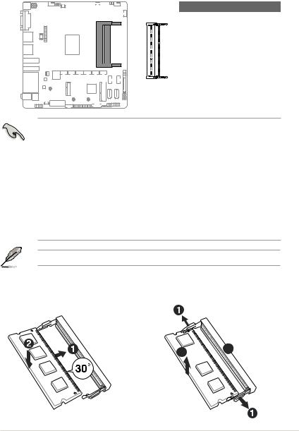
2.4System memory
This motherboard comes with two Double Data Rate 3 Low Voltage (DDR3L) Small
Outline Dual Inline Memory Modules (SO-DIMM) socket. The figure illustrates the location of the DDR3L DIMM socket:
<![endif]>DIMM_A1
<![if ! IE]><![endif]>DIMM_B1
| <![if ! IE]> <![endif]>J3455T-IM-A |
Channel |
Sockets |
|
|
Channel A |
DIMM_A1 |
Channel B |
DIMM_B1 |
IMPORTANT!
•You may install varying memory sizes in Channel A and Channel B. The system maps the total size of the lower-sized channel for the dual-channel configuration. Any excess memory from the higher-sized channel is then mapped for single-channel operation.
•Always install the DIMMS with the same CAS Latency. For an optimum compatibility, we recommend that you install memory modules of the same version or data code (D/C) from the same vendor. Check with the vendor to get the correct memory modules.
•According to Intel® CPU spec, DIMM voltage below 1.35V is recommended to protect the CPU.
NOTE: Visit the ASUS website at www.asus.com for the latest QVL.
To install a SO-DIMM |
To remove a SO-DIMM |
2
 3
3
Chapter 2: Motherboard information |
2-5 |
2.5Jumpers
1.Clear RTC RAM (2-pin CLRTC)
This header allows you to clear the CMOS RTC RAM data of the system setup information such as date, time, and system passwords.
<![endif]>J3455T-IM-A
CLRTC
<![if ! IE]><![endif]>+3V_BAT GND
Connector type HEADER 1x2p, 2.54mm pitch, S/T
To erase the RTC RAM:
1.Turn OFF the computer and unplug the power cord.
2.Use a metal object such as a screwdriver to short the two pins.
3.Plug the power cord and turn ON the computer.
4.Hold down the <Del> key during the boot process and enter BIOS setup to re-enter data.
NOTE: If the steps above do not help, remove the onboard battery and move the jumper again to clear the CMOS RTC RAM data. After clearing the CMOS, reinstall the battery.
2-6 |
J3455T-IM-A/N3350T-IM-A/N4200T-IM-A |
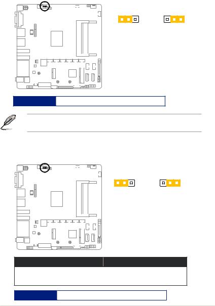
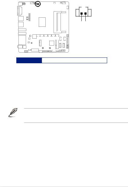
2.WDT Enable jumper (2-pin WDT_EN)
A watchdog timer is an electronic timer that is used to detect and recover from computer malfunctions. The HW WDT (watchdog timer) Enable jumper allows the HW watchdog resets the system automatically even when the system crashes.
<![endif]>J3455T-IM-A
WDT_EN
1 |
2 |
2 |
3 |
jumper closed |
jumper removed |
||
(Default) |
|
|
|
Connector type HEADER 1x2p, 2.54mm pitch, S/T
NOTE: By default, this jumper is set to HW WDT enabled with a jumper cap attached.
3.AT/ATX mode selection (3-pin AT_ATX_SEL)
<![endif]>J3455T-IM-A
AT_ATX_SEL
1 |
2 |
2 |
3 |
jumper closed |
jumper removed |
||
(Default) |
|
|
|
Pins
1-2 (Default) |
ATX mode |
|
|
2-3 |
AT mode |
|
|
Connector type HEADER 1x3p, 2.54mm pitch, S/T
Chapter 2: Motherboard information |
2-7 |
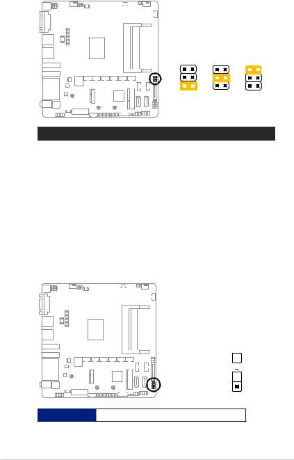
4.COM Ring/+5V/+12V selection (6-pin COM1_SEL)
<![endif]>J3455T-IM-A
COM1_SEL
2 |
1 |
4 |
3 |
6 |
5 |
|
|
|
|
|
|
|
|
|
|
|
|
|
|
|
|
|
|
|
|
|
|
+12V +5V RI (Default)
Setting |
Pins |
|
|
12V |
1-2 |
|
|
5V |
3-4 |
|
|
Ring (Default) |
5-6 |
|
|
5.Chassis intrusion header (4-1 pin_CHASSIS)
This header is for a chassis-mounted intrusion detection sensor or switch. Connect one end of the chassis intrusion sensor or switch cable to this connector. The chassis intrusion sensor or switch sends a low-level signal to this connector
when a chassis component is installed. The signal is then generated as a chassis intrusion event.
<![endif]>J3455T-IM-A
CHASSIS
GND 
 O_CASEOPEN

+5VSB_ATX 
PIN 1
Connector type HEADER 4p, K2, 2.54mm pitch
2-8 |
J3455T-IM-A/N3350T-IM-A/N4200T-IM-A |
Loading...