


M5A78L-M LX PLUS

Motherboard
M5A78L-M LX Series
• M5A78L-M LX V2
• M5A78L-M LX PLUS

ii
Copyright © 2012 ASUSTeK COMPUTER INC. All Rights Reserved.
No part of this manual, including the products and software described in it, may be reproduced,
transmitted, transcribed, stored in a retrieval system, or translated into any language in any form or by any
means, except documentation kept by the purchaser for backup purposes, without the express written
permission of ASUSTeK COMPUTER INC. (“ASUS”).
Product warranty or service will not be extended if: (1) the product is repaired, modied or altered, unless
such repair, modication of alteration is authorized in writing by ASUS; or (2) the serial number of the
product is defaced or missing.
ASUS PROVIDES THIS MANUAL “AS IS” WITHOUT WARRANTY OF ANY KIND, EITHER EXPRESS
OR IMPLIED, INCLUDING BUT NOT LIMITED TO THE IMPLIED WARRANTIES OR CONDITIONS OF
MERCHANTABILITY OR FITNESS FOR A PARTICULAR PURPOSE. IN NO EVENT SHALL ASUS, ITS
DIRECTORS, OFFICERS, EMPLOYEES OR AGENTS BE LIABLE FOR ANY INDIRECT, SPECIAL,
INCIDENTAL, OR CONSEQUENTIAL DAMAGES (INCLUDING DAMAGES FOR LOSS OF PROFITS,
LOSS OF BUSINESS, LOSS OF USE OR DATA, INTERRUPTION OF BUSINESS AND THE LIKE),
EVEN IF ASUS HAS BEEN ADVISED OF THE POSSIBILITY OF SUCH DAMAGES ARISING FROM ANY
DEFECT OR ERROR IN THIS MANUAL OR PRODUCT.
SPECIFICATIONS AND INFORMATION CONTAINED IN THIS MANUAL ARE FURNISHED FOR
INFORMATIONAL USE ONLY, AND ARE SUBJECT TO CHANGE AT ANY TIME WITHOUT NOTICE,
AND SHOULD NOT BE CONSTRUED AS A COMMITMENT BY ASUS. ASUS ASSUMES NO
RESPONSIBILITY OR LIABILITY FOR ANY ERRORS OR INACCURACIES THAT MAY APPEAR IN THIS
MANUAL, INCLUDING THE PRODUCTS AND SOFTWARE DESCRIBED IN IT.
Products and corporate names appearing in this manual may or may not be registered trademarks or
copyrights of their respective companies, and are used only for identication or explanation and to the
owners’ benet, without intent to infringe.
Offer to Provide Source Code of Certain Software
This product contains copyrighted software that is licensed under the General Public License (“GPL”),
under the Lesser General Public License Version (“LGPL”) and/or other Free Open Source Software
Licenses. Such software in this product is distributed without any warranty to the extent permitted by the
applicable law. Copies of these licenses are included in this product.
Where the applicable license entitles you to the source code of such software and/or other additional data,
you may obtain it for a period of three years after our last shipment of the product, either
(1) for free by downloading it from http://support.asus.com/download
or
(2) for the cost of reproduction and shipment, which is dependent on the preferred carrier and the location
where you want to have it shipped to, by sending a request to:
ASUSTeK Computer Inc.
Legal Compliance Dept.
15 Li Te Rd.,
Beitou, Taipei 112
Taiwan
In your request please provide the name, model number and version, as stated in the About Box of the
product for which you wish to obtain the corresponding source code and your contact details so that we
can coordinate the terms and cost of shipment with you.
The source code will be distributed WITHOUT ANY WARRANTY and licensed under the same license as
the corresponding binary/object code.
This offer is valid to anyone in receipt of this information.
ASUSTeK is eager to duly provide complete source code as required under various Free Open Source
Software licenses. If however you encounter any problems in obtaining the full corresponding source
code we would be much obliged if you give us a notication to the email address gpl@asus.com, stating
the product and describing the problem (please DO NOT send large attachments such as source code
archives, etc. to this email address).
E8026
First Edition (V2)
January 2013

iii
Contents
Safety information ...................................................................................... vi
About this guide ........................................................................................ vii
M5A78L-M LX Series specications summary ........................................ ix
Chapter 1 Product introduction
1.1 Welcome! ...................................................................................... 1-1
1.2 Package contents .........................................................................
1-1
1.3 Special features ............................................................................
1-1
1.3.1 Product highlights ...........................................................
1-1
1.3.2 Innovative ASUS features ...............................................
1-3
1.4 Before you proceed .....................................................................
1-5
1.5 Motherboard overview .................................................................
1-6
1.5.1 Placement direction ........................................................
1-6
1.5.2 Screw holes ....................................................................
1-6
1.5.3 Motherboard layout .........................................................
1-7
1.5.4 Layout contents ...............................................................
1-7
1.6 Central Processing Unit (CPU) ...................................................
1-8
1.6.1 Installing the CPU ...........................................................
1-8
1.6.2 Installing the heatsink and fan ......................................
1-10
1.7 System memory .........................................................................
1-11
1.7.1 Overview ........................................................................
1-11
1.7.2 Memory congurations ..................................................
1-12
1.7.3 Installing a DIMM ..........................................................
1-16
1.7.4 Removing a DIMM ........................................................
1-16
1.8 Expansion slots ..........................................................................
1-17
1.8.1 Installing an expansion card .........................................
1-17
1.8.2 Conguring an expansion card .....................................
1-17
1.8.3 PCI slot .........................................................................
1-17
1.8.4 PCI Express 2.0 x1 slots ...............................................
1-17
1.8.5 PCI Express 2.0 x16 slot ...............................................
1-17
1.9 Jumpers ......................................................................................
1-18
1.10 Connectors .................................................................................
1-20
1.10.1 Rear panel ports ...........................................................
1-20
1.10.2 Internal connectors .......................................................
1-21

iv
Contents
1.11 Software support ........................................................................ 1-27
1.11.1 Installing an operating system ......................................
1-27
1.11.2 Support DVD information ..............................................
1-27
Chapter 2 BIOS information
2.1 Managing and updating your BIOS ............................................ 2-1
2.1.1 ASUS Update utility ........................................................
2-1
2.1.2 ASUS EZ Flash 2 utility ...................................................
2-2
2.1.3 ASUS CrashFree BIOS 3 ................................................
2-3
2.2 BIOS setup program ....................................................................
2-4
2.2.1 BIOS menu screen ..........................................................
2-5
2.2.2 Menu bar .........................................................................
2-5
2.2.3 Navigation keys ...............................................................
2-5
2.2.4 Menu items .....................................................................
2-6
2.2.5 Submenu items ...............................................................
2-6
2.2.6 Conguration elds .........................................................
2-6
2.2.7 Pop-up window ...............................................................
2-6
2.2.8 Scroll bar .........................................................................
2-6
2.2.9 General help ...................................................................
2-6
2.3 Main menu ....................................................................................
2-7
2.3.1 System Time [xx:xx:xx] ...................................................
2-7
2.3.2 System Date [Day xx/xx/xxxx] .........................................
2-7
2.3.3
SATA3G_1~6 .................................................................. 2-7
2.3.4 SATA Conguration .........................................................
2-8
2.3.5 System Information .........................................................
2-9
2.4 Advanced menu ...........................................................................
2-9
2.4.1 JumperFree Conguration ............................................
2-10
2.4.2 CPU Conguration ........................................................
2-12
2.4.3 Chipset ..........................................................................
2-14
2.4.4 Onboard Devices Conguration ....................................
2-15
2.4.5 PCIPnP .........................................................................
2-16
2.4.6 USB Conguration ........................................................
2-16

v
Contents
2.5 Power menu ................................................................................ 2-17
2.5.1 Suspend Mode [Auto] ...................................................
2-17
2.5.2 ACPI 2.0 Support [Enabled] ..........................................
2-17
2.5.3 ACPI APIC Support [Enabled] .......................................
2-17
2.5.4 APM Conguration ........................................................
2-17
2.5.5 HW Monitor Conguration .............................................
2-18
2.5.6 Anti Surge Support [Enabled] .......................................
2-18
2.6 Boot menu ..................................................................................
2-19
2.6.1 Boot Device Priority ......................................................
2-19
2.6.2 Boot Settings Conguration ..........................................
2-19
2.6.3 Security .........................................................................
2-20
2.7 Tools menu .................................................................................
2-22
2.7.1 ASUS EZ Flash 2 ..........................................................
2-22
2.7.2 ASUS O.C. Prole .........................................................
2-22
2.8 Exit menu ....................................................................................
2-23
Appendices
Notices .......................................................................................................A-1
ASUS contact information .......................................................................A-3

vi
Safety information
Electrical safety
• To prevent electrical shock hazard, disconnect the power cable from the electrical outlet
before relocating the system.
•
When adding or removing devices to or from the system, ensure that the power cables
for the devices are unplugged before the signal cables are connected. If possible,
disconnect all power cables from the existing system before you add a device.
•
Before connecting or removing signal cables from the motherboard, ensure that all
power cables are unplugged.
•
Seek professional assistance before using an adapter or extension cord. These devices
could interrupt the grounding circuit.
•
Ensure that your power supply is set to the correct voltage in your area. If you are not
sure about the voltage of the electrical outlet you are using, contact your local power
company.
•
If the power supply is broken, do not try to x it by yourself. Contact a qualied service
technician or your retailer.
Operation safety
• Before installing the motherboard and adding devices on it, carefully read all the manuals
that came with the package.
•
Before using the product, ensure all cables are correctly connected and the power
cables are not damaged. If you detect any damage, contact your dealer immediately.
•
To avoid short circuits, keep paper clips, screws, and staples away from connectors,
slots, sockets and circuitry.
•
Avoid dust, humidity, and temperature extremes. Do not place the product in any area
where it may become wet.
•
Place the product on a stable surface.
•
If you encounter technical problems with the product, contact a qualied service
technician or your retailer.

vii
About this guide
This user guide contains the information you need when installing and conguring the
motherboard.
How this guide is organized
This guide contains the following parts:
• Chapter 1: Product introduction
This chapter describes the features of the motherboard and the new technology it
supports.
• Chapter 2: BIOS information
This chapter tells how to change system settings through the BIOS Setup menus.
Detailed descriptions of the BIOS parameters are also provided.
Where to nd more information
Refer to the following sources for additional information and for product and software
updates.
1. ASUS websites
The ASUS website provides updated information on ASUS hardware and software
products. Refer to the ASUS contact information.
2. Optional documentation
Your product package may include optional documentation, such as warranty yers,
that may have been added by your dealer. These documents are not part of the
standard package.

viii
Conventions used in this guide
To ensure that you perform certain tasks properly, take note of the following symbols used
throughout this manual.
DANGER/WARNING: Information to prevent injury to yourself when trying to
complete a task.
CAUTION: Information to prevent damage to the components when trying to
complete a task
IMPORTANT: Instructions that you MUST follow to complete a task. .
NOTE: Tips and additional information to help you complete a task.
Typography
Bold text Indicates a menu or an item to select.
Italics Used to emphasize a word or a phrase.
<Key> Keys enclosed in the less-than and greater-than sign
means that you must press the enclosed key.
Example: <Enter> means that you must press the Enter or
Return key.
<Key1> + <Key2> + <Key3> If you must press two or more keys simultaneously, the key
names are linked with a plus sign (+).
ix
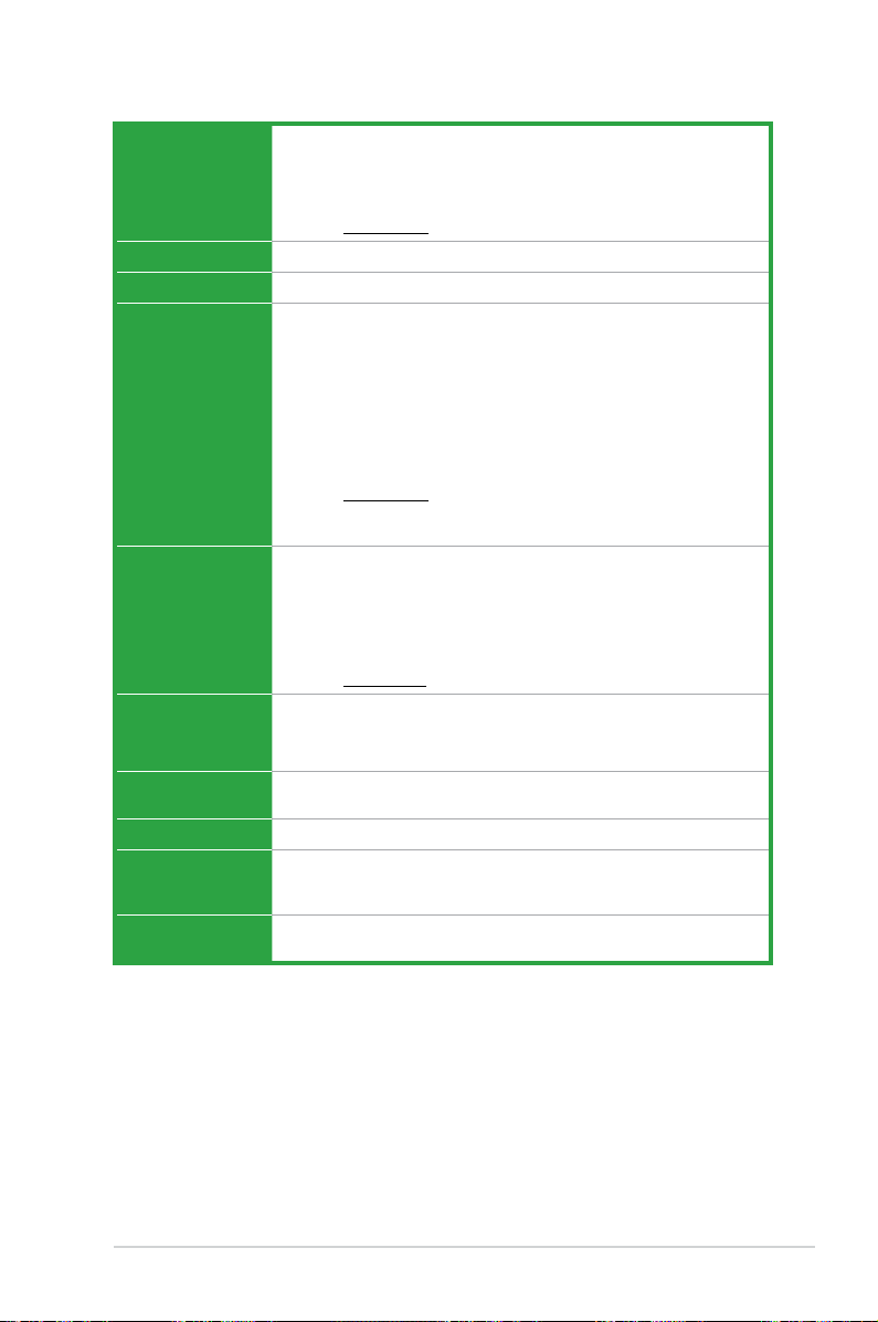
M5A78L-M LX Series specications summary
(continued on the next page)
APU
AMD
®
Socket AM3+ for AMD
®
FX™ / Phenom™ II / Athlon™ II / Sempron™
100 series processors
AMD
®
Cool n’ Quiet™ Technology
Supports CPU up to 125W
• Refer to www.asus.com for the AMD
®
APU support list.
Chipset
AMD
®
760G (780L) / SB710
Front side bus
Up to 5200 MT/s HyperTransport™ 3.0 interface
Memory
2 x 240-pin DIMM slots support maximum 16GB unbuffered ECC and non-
ECC DDR3 1866(O.C.) / 1600(O.C.) / 1333 / 1066 MHz memory modules
Dual-channel memory architecture
• AMD
®
FX™ Series CPU on this motherboard supports up to DDR3 1866MHz as
its standard memory frequency.
• Due to CPU specications, AMD
®
100 and 200 series CPUs support up to
DDR3 1066MHz. With ASUS design, this motherboard can support up to DDR3
1333MHz.
• When overclocking, some AMD CPU models may not support DDR3 1600 MHz
or higher frequency DIMMs.
• Refer to
www.asus.com for the latest Memory QVL (Qualied Vendors List).
• Use a 64-bit Windows
®
OS if you want to install 4GB or more memory on the
motherboard.
Graphics
Integrated AMD
®
Radeon™ HD 3000 GPU
Supports maximum shared memory of 1GB
Supports RGB with a maximum resolution of 2560 x 1440 (@75Hz)
Supports Microsoft
®
DirectX 11
Supports Hybrid CrossFireX™
• Refer to www.amd.com for the discrete GPUs that support Hybrid CrossFireX™.
Expansion slots
1 x PCIe 2.0 x16 slot
2 x PCIe 2.0 x1 slots
1 x PCI slot
Storage / RAID
6 x Serial ATA 3.0Gb/s connectors support RAID 0, RAID 1, RAID 10 and
JBOD congurations
LAN
Realtek
®
RTL8111E PCIe Gigabit LAN controller
Audio
Realtek
®
ALC887 8-channel High Denition Audio CODEC
• Use a chassis with HD audio module in the front panel to support an 8-channel
audio output.
USB
Supports up to 10 x USB 2.0/1.1 ports (6 ports at the mid-board, 4 ports at
the back panel)

x
M5A78L-M LX Series specications summary
*Specications are subject to change without notice.
ASUS unique
features
ASUS Core Unlocker
ASUS Turbo Key
ASUS Q-Fan
ASUS AI Charger
ASUS EPU-4 Engine
ASUS Anti-Surge
ASUS EZ Flash2
ASUS MyLogo2
ASUS C.P.R. (CPU Parameter Recall)
Special features
100% All high quality conductive polymer (M5A78L-M LX PLUS only)
Back Panel I/O
ports
1 x PS/2 mouse port
1 x PS/2 keyboard port
1 x COM port
1 x LPT port
1 x D-Sub output port
1 x LAN (RJ-45) port
4 x USB 2.0/1.1 ports
8-channel audio I/O ports (3-jack)
Internal I/O
connectors /
buttons / switches
3 x USB 2.0/1.1 connectors support additional 6 USB 2.0/1.1 ports
6 x SATA 3.0Gb/s connectors
1 x CPU fan connector
1 x Chassis fan connector
1 x Front panel audio connector
1 x S/PDIF output connector
1 x System panel connector
1 x Speaker connector
1 x 24-pin ATX power connector
1 x 4-pin ATX 12V power connector
BIOS
16 Mb Flash ROM, AMI BIOS, PnP, DMI2.0
WfM2.0, ACPI2.0a, SM BIOS 2.5
Support DVD
Drivers
ASUS Update
ASUS utilities
Anti-Virus software (OEM version)
Form factor
MicroATX form factor: 9.6 in x 8.0 in (24.4 cm x 20.3 cm)
1.2 Package contents
Check your motherboard package for the following items.
Motherboard ASUS M5A78L-M LX Series motherboard
Cables 2 x Serial ATA 3.0Gb/s cables
Accessories 1 x I/O shield
Application DVD ASUS motherboard Support DVD
Documentation User Manual
• M5A78L-M LX Series motherboards include M5A78L-M LX PLUS and M5A78L-M LX V2
two models. The package contents vary from models. The layout illustrations in this user
guide are for M5A78L-M LX PLUS only.
• If any of the items is damaged or missing, contact your retailer.
Chapter 1
Product introduction
1.3 Special features
1.3.1 Product highlights
1.1 Welcome!
Thank you for buying an ASUS
®
M5A78L-M LX Series motherboard!
The motherboard delivers a host of new features and latest technologies, making it another
standout in the long line of ASUS quality motherboards!
Before you start installing the motherboard, and hardware devices on it, check the items in
your package with the list below.
AMD
®
FX™ / Phenom™ II / Athlon™ II / Sempron™ 100 series
CPU support
This motherboard supports AMD
®
Socket AM3+ multi-core processors
with unique L3 cache and delivers better overclocking capabilities with
less power consumption. It features dual-channel DDR3 memory support
and accelerates data transfer rate up to 5200MT/s via HyperTransport™
3.0-based system bus. This motherboard also supports AMD
®
CPUs in
the new 32nm manufacturing process.
ASUS M5A78L-M LX Series 1-1

HyperTransport™ 3.0 support
HyperTransport™ 3.0 technology provides 2.6 times more bandwidth
than HT1.0 that radically improves system efciency for a smoother and
faster computing environment.
AMD
®
Cool ‘n’ Quiet Technology
This motherboard supports the AMD
®
Cool ‘n’ Quiet technology which
monitors system operation and automatically adjusts CPU voltage and
frequency for a cool and quiet operating environment.
Dual-Channel DDR3 1866 (O.C.) support
This motherboard supports DDR3 memory that features data transfer
rates of 1866 (O.C.)/1600 (O.C.)/1333/1066 MHz to meet the higher
bandwidth requirements of the latest operating system, 3D graphics,
multimedia, and Internet applications.
Hybrid CrossFireX™ support
ATI Hybrid CrossFireX™ technology greatly boosts graphics performance
with an onboard GPU and a discrete GPU.
• Hybrid CrossFireX™ is supported by Windows
®
Vista / Windows
®
7
OS only.
• Refer to
www.amd.com for the discrete GPUs that support Hybrid CrossFireX™.
Gigabit LAN solution
The onboard LAN controller is a highly integrated Gb LAN controller. It is
enhanced with an ACPI management function to provide efcient power
management for advanced operating systems.
Serial ATA 3Gb/s technology and RAID support
This motherboard supports hard drives based on the Serial ATA (SATA)
3Gb/s storage specication, delivering enhanced scalability and doubling
the bus bandwidth for high-speed data retrieval and save. It also supports
RAID 0, RAID 1, and RAID 0+1 congurations for Serial ATA hard drives.
100% All High-quality Conductive Polymer Capacitors
(M5A78L-M LX PLUS only)
This motherboard uses all high-quality conductive polymer capacitors for
durability, improved lifespan, and enhanced thermal capacity.
Chapter 1: Product introduction1-2
1.3.2 Innovative ASUS features
1 2
Core Unlocker
ASUS Core Unlocker simplies the activation of a latent AMD
®
CPU-
with just pressing a key. Enjoy an instant performance boost by simply
unlocking the extra cores, without performing complicated BIOS changes.
ASUS Turbo Key
ASUS Turbo Key allows you to turn the PC power button into
an overclocking button. After the easy setup, Turbo Key boosts
performances without interrupting ongoing work or games, simply through
pressing the button.
ASUS MyLogo2™
Turn your favorite photos into 256-color boot logos to personalize your
system.
ASUS EZ Flash 2
ASUS EZ Flash 2 allows you to update the BIOS from a USB ash disk
before entering the OS.
ASUS Q-Fan
ASUS Q-Fan technology intelligently adjusts the CPU fan speed
according to system loading to ensure a quiet, cool, and efcient
operation.
ASUS Anti-Surge Protection
This special design prevents expensive devices and the motherboard
from damage caused by power surges from switching power supply
(PSU).
ASUS EPU
ASUS EPU is a unique power saving technology that detects the current
system loadings and adjusts the power consumption in real time.
C.P.R. (CPU Parameter Recall)
The BIOS C.P.R. feature automatically restores the CPU default settings
when the system hangs due to overclocking failure. C.P.R. eliminates the
need to open the system chassis and clear the RTC data. Simply shut
down and reboot the system, and the BIOS automatically restores the
CPU parameters to their default settings.
ASUS M5A78L-M LX Series 1-3

ErP ready
The motherboard is European Union´s Energy-related Products (ErP)
ready, and ErP requires products to meet certain energy efciency
requirements in regards to energy consumptions. This is in line with
ASUS vision of creating environment-friendly and energy-efcient
products through product design and innovation to reduce carbon
footprint of the product and thus mitigate environmental impacts.
Chapter 1: Product introduction1-4
1.4 Before you proceed
Take note of the following precautions before you install motherboard components or change
any motherboard settings.
• Unplug the power cord from the wall socket before touching any component.
• Before handling components, use a grounded wrist strap or touch a safely grounded
object or a metal object, such as the power supply case, to avoid damaging them due to
static electricity.
• Hold components by the edges to avoid touching the ICs on them.
• Whenever you uninstall any component, place it on a grounded antistatic pad or in the
bag that came with the component.
• Before you install or remove any component, switch off the ATX power supply and
detach its power cord. Failure to do so may cause severe damage to the motherboard,
peripherals, or components.
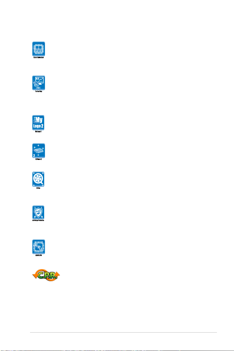
Onboard LED
The motherboard comes with a standby power LED that lights up to indicate that the system
is ON, in sleep mode, or in soft-off mode. This is a reminder that you should shut down
the system and unplug the power cable before removing or plugging in any motherboard
component. The illustration below shows the location of the onboard LED.
SB_PWR
ON
Standby Power Powered Off
OFF
M5A78L-M LX PLUS
M5A78L-M LX PLUS Onboard LED
ASUS M5A78L-M LX Series 1-5
M5A78L-M LX PLUS
1.5 Motherboard overview
1.5.1 Placement direction
When installing the motherboard, ensure that you place it into the chassis in the correct
orientation. The edge with external ports goes to the rear part of the chassis as indicated in
the image below.
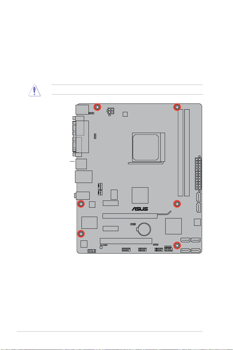
DO NOT overtighten the screws! Doing so can damage the motherboard.
1.5.2 Screw holes
Place six screws into the holes indicated by circles to secure the motherboard to the chassis.
Place this side towards
the rear of the chassis.
Chapter 1: Product introduction1-6
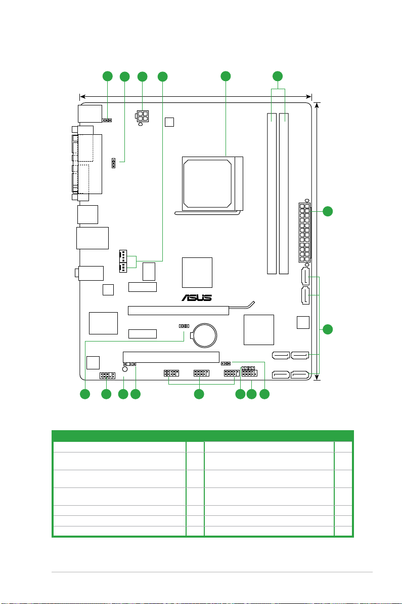
1.5.3 Motherboard layout
1.5.4 Layout contents
Connectors/Jumpers/Slots Page Connectors/Jumpers/Slots Page
1. Keyboard power (3-pin KBPWR) 1-19 8. System panel connector (10-1 pin F_PANEL) 1-24
2. USB device wake-up (3-pin USBPW1-4,
USBPW5-10)
1-19 9. Speaker connector (4- pin SPEAKER) 1-24
3. ATX power connectors (24-pin EATXPWR, 4-pin
ATX12V)
1-22 10. USB connectors (10-1 pin USB56, USB78,
USB910)
1-25
4. CPU and chassis fan connectors (4-pin
CPU_FAN and 3-pin CHA_FAN)
1-26 11. Digital audio connector (4-1 pin SPDIF_OUT) 1-25
5. AMD CPU socket 1-8 12. Onboard LED (SB_PWR) 1-5
6. DDR3 DIMM sockets 1-11 13. Front panel audio connector (10-1 pin AAFP) 1-21
7. Serial ATA connectors (7-pin SATA1-6) 1-23 14. Clear RTC RAM (CLRTC) 1-18
M5A78L-M LX PLUS
PCIEX16
PCIEX1_1
PCIEX1_2
PCI1
USB910 USB78 USB56
AAFP
SPDIF_OUT
ATX12V
EPU
EATXPWR
CPU_FAN
Lithium Cell
CMOS Power
Super
I/O
ALC
887
RTL
8111E
ICS
9LPRS483
KBMS
16Mb
BIOS
SB_PWR
SPEAKER
CLRTC
USBPW5-10
USBPW1-4
KBPWR
20.3cm(8.0in)
24.4cm(9.6in)
AMD
®
760G
AMD
®
SB710
SOCKET AM3+
DDR3 DIMM_A1 (64bit, 240-pin module)
DDR3 DIMM_B1 (64bit, 240-pin module)
SATA3G_3SATA3G_1
SATA3G_4SATA3G_2
SATA3G_5SATA3G_6
CHA_FAN
F_PANEL
AUDIO
LAN1_USB12
USB34
LPT
COM1
VGA
2 3 4
5 6
3
1
101112 89 21314
7
ASUS M5A78L-M LX Series 1-7
1.6 Central Processing Unit (CPU)
This motherboard comes with an AM3+ socket designed for FX™ / Phenom™ II / Athlon™ II /
Sempron™ 100 series processors.
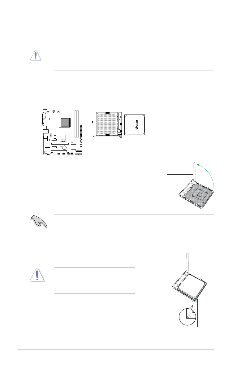
1.6.1 Installing the CPU
To install a CPU:
1. Locate the CPU socket on the motherboard.
2. Press the lever sideways to unlock the
socket, then lift it up to a 90°-100° angle.
Ensure that the socket lever is lifted up to a 90°-100° angle; otherwise, the CPU will not t
in completely.
3. Position the CPU above the socket such that the CPU
corner with the gold triangle matches the socket corner
with a small triangle.
4. Carefully insert the CPU into the socket until it ts in place.
The CPU ts only in one correct orientation.
DO NOT force the CPU into the socket to
prevent bending the pins and damaging the
CPU!
The AM3+ socket has a different pinout from the AM2+/AM2 socket. Ensure that you use a
CPU designed for the AM3+ socket. The CPU ts in only one correct orientation. DO NOT
force the CPU into the socket to prevent bending the pins and damaging the CPU!
M5A78L-M LX PLUS
M5A78L-M LX PLUS CPU AM3+
Socket lever
Gold triangle
Small triangle
Chapter 1: Product introduction1-8
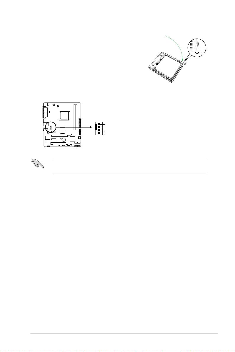
5. When the CPU is in place, push down the socket
lever to secure the CPU. The lever clicks on the side
tab to indicate that it is locked.
6. Install a CPU heatsink and fan following the
instructions that comes with the heatsink package.
You can also refer to section 1.6.2 Installing
heatsink and fan for instructions.
7. Connect the CPU fan cable to the CPU_FAN connector on the motherboard.
DO NOT forget to connect the CPU fan connector! Hardware monitoring errors can occur if
you fail to plug this connector.
M5A78L-M LX PLUS
M5A78L-M LX PLUS CPU fan connector
CPU_FAN
GND
CPU FAN PWR
CPU FAN IN
CPU FAN PWM
ASUS M5A78L-M LX Series 1-9
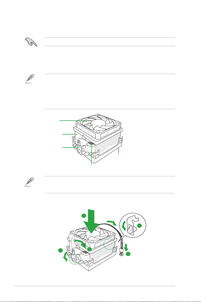
1.6.2 Installing the heatsink and fan
Ensure that you use only AMD-certied heatsink and fan assembly.
To install the CPU heatsink and fan:
1. Place the heatsink on top of the installed CPU, ensuring that the heatsink ts properly
on the retention module base.
• The retention module base is already installed on the motherboard upon purchase.
• You do not have to remove the retention module base when installing the CPU or
installing other motherboard components.
• If you purchased a separate CPU heatsink and fan assembly, ensure that a Thermal
Interface Material is properly applied to the CPU heatsink or CPU before you install the
heatsink and fan assembly.
CPU Fan
CPU Heatsink
Retention bracket
Retention bracket lock
Retention Module Base
Your boxed CPU heatsink and fan assembly should come with installation instructions for
the CPU, heatsink, and the retention mechanism. If the instructions in this section do not
match the CPU documentation, follow the latter.
2. Attach one end of the retention bracket to the retention module base.
1
3
4
5
2
Chapter 1: Product introduction1-10
 Loading...