


D I S A S S E M B L Y P R O C E D U R E
3Chapter
Disassembly Procedure
Please follow the information provided in this section to perform the complete disassembly procedure of the notebook. Be sure to use proper tools described before.
SUS M6000 Series Notebook consists of various modules. This chapter describes the Aprocedures for the complete notebook disassembly. In addition, in between procedures, the detailed disassembly procedure of individual modules will be provided for your
service needs.
The disassembly procedure consists of the following steps:
•Battery Module
•Optical Drive Module
•HDD Module
•Second Memory Module
•CPU Module
•Keyboard Module
•First Memory Module
•Mini PCI Module
•LCD Module
•Top Case Module
•Motherboard Module
•Bottom Case Module
3 - 1
D I S A S S E M B L Y P R O C E D U R E
B A T T E R Y
Battery Module
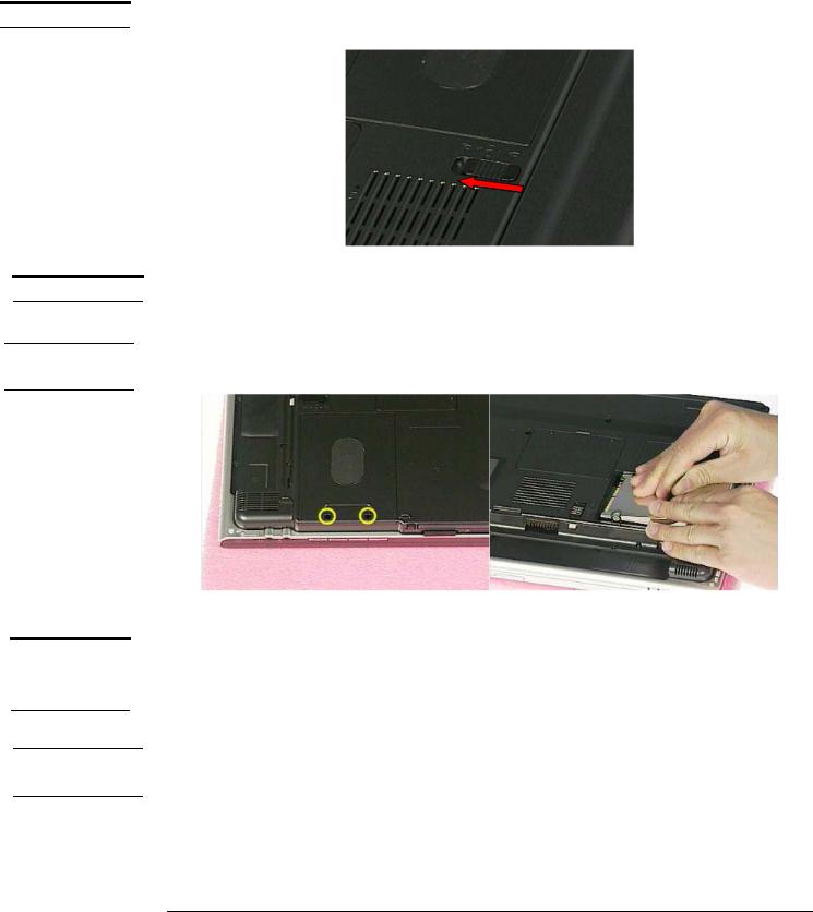
The illustration below shows how to remove the battery module.
1. Press latch to open the battery module, then lift battery module away from the system.
H D D M O D U L E
H D D M O D U L E
R E M O V A L
S E C O N D
M E M O R Y
M O D U L E
M E M O R Y
R E M O V A L
HDD Module
The illustrations below show how to remove the HDD module from the notebook.
Removing HDD Module
Remove 2 screws(M2*6L(K)), then remove the HDD cover and pull the hard disk module toward the direction of the arrow and lift it up and take it out.
M2*6L
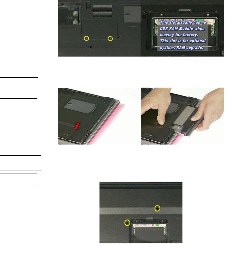
Second Memory Module
The M6000 Series Notebook do not have onboard RAM. There are two SO-DIMM sockets for installing SO-DIMM RAM. It can upgrade the total memory size up to 2GB with a 1GB module on each socket.
Removing Memory module
1. Remove 2 screws(M2*3L(K) ) , then take the memory DIMM cover away.
3 - 2
O P T I C A L
D R I V E
R E M O V A L
K E Y B O A R D
D I S A S S E M B L Y
K / B C O V E R R E M O V A L
D I S A S S E M B L Y P R O C E D U R E
M2*3L
Optical Drive Module
Press latch here then pull it out.
Keyboard Module
The illustration of below shows how to remove the keyboard
Removing Keyboard Cover
1. Remove 2 screws (M2.5*6L(K)) on the bottom case.
M2.5*6L
3 - 3
D I S A S S E M B L Y P R O C E D U R E
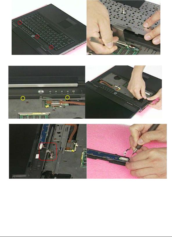
2.Unlock 3 keyboard latches then pull out the keyboard forward and lay the keyboard on the front side .
3.Remove 2 screws on the keyboard cover , then use tweezers to disconnect the keyboard two covers and lift it up.
M2*3L
4. Loosen the switch board cable and take the keyboard cover away , then remove the switch cable
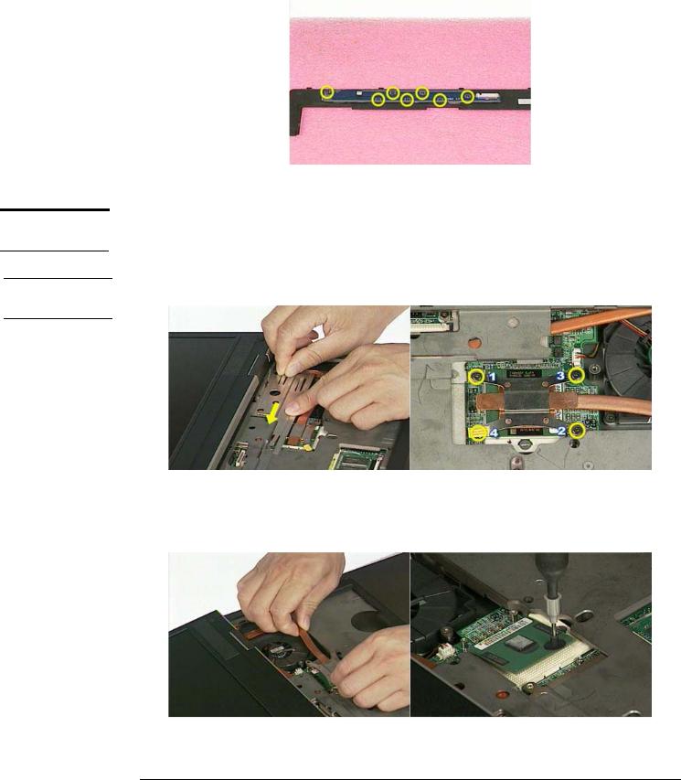
5. Remove 7 screws and take the switch board away.
3 - 4
D I S A S S E M B L Y P R O C E D U R E
C P U M O D U L E
R E M O V A L
C P U
R E M O V A L
M2*3L
CPU Module
The illustrations below show how to remove the CPU module from the notebook.
Removing CPU
1. Take the Fan bracket away then remove 4 screws (M2*6L(K)).
M2*6L
2.Remove Thermal module and open the CPU Socket’s latch to loosen the CPU.(The use the CPU vacuum hand pump to “suck up” the CPU and lift the CPU away.)
3 - 5

F I R S T
M E M O R Y
M O D U L E
R E M O V A L
W I R E L E S S L A N M O D U L E
W I R E L E S S
L A N
R E M O V A L
D I S A S S E M B L Y P R O C E D U R E
First Memory Module
The first memory module is under keyboard. Open the two latches to pop up memory module at 45 degrees angle then pull it out .
Mini PCI Module
This slot usually has Wireless LAN module when leaving the factory, this slot is for optional system upgrade.
Removing Wireless LAN Module
1. Remove 1 screw(M2*3L(K)), then take the mini-PCI cover off.
M2*3L
2.Disconnect 2 antenna cables, then open two latches to pop up wireless LAN module at 45 degrees angle and pull it out.
3 - 6
 Loading...