


 Loading...
ASUS Desktop PC
User Guide
Smart Card
SD/MMC/MS
D540MA |
D540MB |
<![endif]>Smart Card SD/MMC/MS
D540MC |
D540SA |

E14639
First Edition
August 2018
Copyright © 2018 ASUSTeK Computer Inc. All Rights Reserved.
No part of this manual, including the products and software described in it, may be reproduced, transmitted, transcribed, stored in a retrieval system, or translated into any language in any form or by any means, except documentation kept by the purchaser for backup purposes, without the express written permission of ASUSTeK Computer Inc. (“ASUS”).
Product warranty or service will not be extended if: (1) the product is repaired, modified or altered, unless such repair, modification of alteration is authorized in writing by ASUS; or (2) the serial number of the product is defaced or missing.
ASUS PROVIDES THIS MANUAL “AS IS”WITHOUT WARRANTY OF ANY KIND, EITHER EXPRESS OR IMPLIED, INCLUDING BUT NOT LIMITED TO THE IMPLIED WARRANTIES OR CONDITIONS OF MERCHANTABILITY OR FITNESS FOR A PARTICULAR PURPOSE. IN NO EVENT SHALL ASUS, ITS DIRECTORS, OFFICERS, EMPLOYEES OR AGENTS BE LIABLE FOR ANY INDIRECT, SPECIAL, INCIDENTAL, OR CONSEQUENTIAL DAMAGES (INCLUDING DAMAGES FOR LOSS OF PROFITS, LOSS OF BUSINESS, LOSS OF USE OR DATA, INTERRUPTION OF BUSINESS AND THE LIKE), EVEN IF ASUS HAS BEEN ADVISED OF THE POSSIBILITY OF SUCH DAMAGES ARISING FROM ANY DEFECT OR ERROR IN THIS MANUAL OR PRODUCT.
SPECIFICATIONS AND INFORMATION CONTAINED IN THIS MANUAL ARE FURNISHED FOR INFORMATIONAL USE ONLY, AND ARE SUBJECT TO CHANGE AT ANY TIME WITHOUT NOTICE, AND SHOULD NOT BE CONSTRUED AS A COMMITMENT BY ASUS. ASUS ASSUMES NO RESPONSIBILITY OR LIABILITY FOR ANY ERRORS OR INACCURACIES THAT MAY APPEAR IN THIS MANUAL, INCLUDING THE PRODUCTS AND SOFTWARE DESCRIBED IN IT.
Products and corporate names appearing in this manual may or may not be registered trademarks or copyrights of their respective companies, and are used only for identification or explanation and to the owners’ benefit, without intent to infringe.
2

Contents |
|
|
Notices ................................................................................................................................................ |
|
5 |
Safety information.......................................................................................................................... |
|
10 |
Conventions used in this guide................................................................................................. |
11 |
|
Where to find more information............................................................................................... |
11 |
|
Package contents............................................................................................................................ |
|
12 |
Chapter 1 |
Getting started |
|
Welcome!........................................................................................................................................... |
|
13 |
Getting to know your computer............................................................................................... |
13 |
|
Setting up your computer........................................................................................................... |
29 |
|
Turning your computer ON......................................................................................................... |
34 |
|
Chapter 2 |
Connecting devices to your computer |
|
Connecting a USB storage device............................................................................................. |
35 |
|
Removing a USB storage device................................................................................................ |
37 |
|
Connecting microphone and speakers.................................................................................. |
38 |
|
Changing to the external audio output................................................................................. |
42 |
|
Connecting multiple external displays................................................................................... |
43 |
|
Chapter 3 |
Using your computer |
|
Proper posture when using your Desktop PC...................................................................... |
45 |
|
Using the memory card reader (optional)............................................................................. |
46 |
|
Using the optical drive (on selected models only)............................................................. |
47 |
|
Configuring the USB ports using the BIOS............................................................................ |
48 |
|
Configuring the HDD security setting using the BIOS...................................................... |
49 |
|
Chapter 4 |
Connecting to the Internet |
|
Wired connection........................................................................................................................... |
|
51 |
Wi-Fi connection (on selected models only)......................................................................... |
58 |
|
Chapter 5 |
Using ASUS Business Manager |
|
ASUS Business Manager............................................................................................................... |
59 |
|
Chapter 6 |
Troubleshooting |
|
Troubleshooting.............................................................................................................................. |
|
69 |
3

Contents
Appendix
Windows® 7 / Windows® 10 User Manual
Chapter 1 |
Using Windows ® 7 |
|
Preloading the USB 2.0/3.0 drivers for Windows® 7 installation |
....................................79 |
|
Starting for the first time.............................................................................................................. |
84 |
|
Using Windows® 7 desktop.......................................................................................................... |
85 |
|
Managing your files and folders................................................................................................ |
87 |
|
Restoring your system settings.................................................................................................. |
89 |
|
Protecting your computer........................................................................................................... |
90 |
|
Getting Windows® Help and Support...................................................................................... |
91 |
|
Recovering your system............................................................................................................... |
92 |
|
Chapter 2 |
Using Windows ® 10 |
|
Starting for the first time.............................................................................................................. |
95 |
|
Using the Windows® 10 UI............................................................................................................ |
96 |
|
Keyboard shortcuts |
..................................................................................................................... |
100 |
ASUS contact information |
|
|
ASUS contact information........................................................................................................ |
102 |
|
4

Notices
ASUS Recycling/Takeback Services
ASUS recycling and takeback programs come from our commitment to the highest standards for protecting our environment. We believe in providing solutions for you to be able to responsibly recycle our products, batteries, other components, as well as the packaging materials. Please go to http://csr.asus.com/english/Takeback.htm for the detailed recycling information in different regions.
REACH
Complying with the REACH (Registration, Evaluation, Authorisation, and Restriction of Chemicals) regulatory framework, we published the chemical substances in our products at ASUS REACH website at http://csr.asus.com/english/REACH.htm
Federal Communications Commission Statement
This device complies with Part 15 of the FCC Rules. Operation is subject to the following two conditions:
•This device may not cause harmful interference; and
•This device must accept any interference received including interference that may cause undesired operation.
This equipment has been tested and found to comply with the limits for a Class B digital device, pursuant to Part 15 of the FCC Rules. These limits are designed to provide reasonable protection against harmful interference in a residential installation. This equipment generates, uses and can radiate radio frequency energy and, if not installed and used in accordance with manufacturer’s instructions, may cause harmful interference to radio communications. However, there is no guarantee that interference will not occur in a particular installation. If this equipment does cause harmful interference to radio or television reception, which can be determined by turning the equipment off and on, the user is encouraged to try to correct the interference by one or more of the following measures:
•Reorient or relocate the receiving antenna.
•Increase the separation between the equipment and receiver.
•Connect the equipment to an outlet on a circuit different from that to which the receiver is connected.
•Consult the dealer or an experienced radio/TV technician for help.
The use of shielded cables for connection of the monitor to the graphics card is required to assure compliance with FCC regulations. Changes or modifications to this unit not expressly approved by the party responsible for compliance could void the user’s authority to operate this equipment.
Lithium Battery Warning
CAUTION: Danger of explosion if battery is incorrectly replaced. Replace only with the same or equivalent type recommended by the manufacturer. Dispose of used batteries according to the manufacturer’s instructions.
5
Avertissement relatif aux batteries Lithium
ATTENTION ! Danger d’explosion si la batterie n’est pas correctement remplacée. Remplacer uniquement avec une batterie de type semblable ou équivalent, recommandée par le fabricant. Jeter les batteries usagées conformément aux instructions du fabricant.
IC: Canadian Compliance Statement
Complies with the Canadian ICES-003 Class B specifiications. This device complies with RSS 210 of Industry Canada. This Class B device meets all the requirements of the Canadian interferencecausing equipment regulations.
This device complies with Industry Canada license exempt RSS standard(s). Operation is subject to the following two conditions: (1) this device may not cause interference, and (2) this device must accept any interference, including interference that may cause undesired operation of the device.
Déclaration de conformité d’Industrie Canada
Cet appareil numérique de la classe B est conforme à la norme NMB-003 du Canada. Cet appareil numérique de la classe B respecte toutes les exigences du Règlement sur le matériel brouilleur du Canada.
Le présent appareil est conforme aux normes CNR d’Industrie Canada applicables aux appareils radio exempts de licence. Son utilisation est sujette aux deux conditions suivantes : (1) cet appareil ne doit pas créer d’interférences et (2) cet appareil doit tolérer tout type d’interférences, y compris celles susceptibles de provoquer un fonctionnement non souhaité de l’appareil.
Canadian Department of Communications Statement
This digital apparatus does not exceed the Class B limits for radio noise emissions from digital apparatus set out in the Radio Interference Regulations of the Canadian Department of Communications.
This class B digital apparatus complies with Canadian ICES-003.
VCCI: Japan Compliance Statement
VCCI Class B Statement
KC: Korea Warning Statement
6

RF Equipment Notices
CE: European Community Compliance Statement
The equipment complies with the RF Exposure Requirement 1999/519/EC, Council Recommendation of 12 July 1999 on the limitation of exposure of the general public to electromagnetic fields (0–300 GHz). This wireless device complies with the R&TTE Directive.
Wireless Radio Use
This device is restricted to indoor use when operating in the 5.15 to 5.25 GHz frequency band.
Exposure to Radio Frequency Energy
The radiated output power of the Wi-Fi technology is below the FCC radio frequency exposure limits. Nevertheless, it is advised to use the wireless equipment in such a manner that the potential for human contact during normal operation is minimized.
FCC Bluetooth Wireless Compliance
The antenna used with this transmitter must not be colocated or operated in conjunction with any other antenna or transmitter subject to the conditions of the FCC Grant.
Bluetooth Industry Canada Statement
This Class B device meets all requirements of the Canadian interference-causing equipment regulations.
Cet appareil numérique de la Class B respecte toutes les exigences du Règlement sur le matériel brouilleur du Canada.
BSMI: Taiwan Wireless Statement
Japan RF Equipment Statement
KC (RF Equipment)
India E-Waste (Management) Rules 2016
This product complies with the "India E-Waste (Management) Rules, 2016" and prohibits use of lead, mercury, hexavalent chromium, polybrominated biphenyls (PBBs) and polybrominated diphenyl ethers (PBDEs) in concentrations exceeding 0.1% by weight in homogenous materials and 0.01 % by weight in homogenous materials for cadmium, except for the exemptions listed in Schedule II of the Rule.
7

Simplified EU Declaration of Conformity
ASUSTek Computer Inc. hereby declares that this device is in compliance with the essential requirements and other relevant provisions of Directive 2014/53/EU. Full text of EU declaration of conformity is available at https://www.asus.com/support/.
The Wi-Fi operating in the band 5150-5350MHz shall be restricted to indoor use for countries listed in the table below:
AT |
BE |
BG |
CZ |
DK |
EE |
FR |
|
|
|
|
|
|
|
DE |
IS |
IE |
IT |
EL |
ES |
CY |
|
|
|
|
|
|
|
LV |
LI |
LT |
LU |
HU |
MT |
NL |
|
|
|
|
|
|
|
NO |
PL |
PT |
RO |
SI |
SK |
TR |
|
|
|
|
|
|
|
FI |
SE |
CH |
UK |
HR |
|
|
|
|
|
|
|
|
|
ENERGY STAR is a joint program of the U.S. Environmental Protection Agency and the U.S. Department of Energy helping us all save money and protect the environment through energy efficient products and practices.
All ASUS products with the ENERGY STAR logo comply with the ENERGY STAR standard, and the power management feature is enabled by default. The monitor and computer are automatically set to sleep after 10 and 30 minutes of user inactivity. To wake
your computer, click the mouse or press any key on the keyboard.
Please visit http://www.energystar.gov/powermanagement for detail information on power management and its benefits to the environment. In addition, please visit http:// www.energystar.gov for detail information on the ENERGY STAR joint program.
*Note: Energy Star is NOT supported on Freedos and Linux-based products.
8

Optical Drive Safety Information
Laser Safety Information
CD-ROM Drive Safety Warning
CLASS 1 LASER PRODUCT
WARNING! To prevent exposure to the optical drive’s laser, do not attempt to disassemble or repair the optical drive by yourself. For your safety, contact a professional technician for assistance.
Service warning label
WARNING! INVISIBLE LASER RADIATION WHEN OPEN. DO NOT STARE INTO BEAM OR VIEW DIRECTLY WITH OPTICAL INSTRUMENTS.
CDRH Regulations
The Center for Devices and Radiological Health (CDRH) of the U.S. Food and Drug Administration implemented regulations for laser products on August 2, 1976. These regulations apply to laser products manufactured from August 1, 1976. Compliance is mandatory for products marketed in the United States.
WARNING! Use of controls or adjustments or performance of procedures other than those specified herein or in the laser product installation guide may result in hazardous radiation exposure.
9
Safety information
Disconnect the AC power and peripherals before cleaning. Wipe the Desktop PC using a clean cellulose sponge or chamois cloth dampened with solution of nonabrasive detergent and a few drops of warm water then remove any extra moisture with a dry cloth.
•DO NOT place on uneven or unstable work surfaces. Seek servicing if the casing has been damaged.
•DO NOT expose to dirty or dusty environments. DO NOT operate during a gas leak.
•DO NOT place or drop objects on top and do not shove any foreign objects into the Desktop PC.
•DO NOT expose to strong magnetic or electrical fields.
•DO NOT expose to or use near liquids, rain, or moisture. DO NOT use the modem during electrical storms.
•Battery safety warning: DO NOT throw the battery in fire. DO NOT short circuit the contacts. DO NOT disassemble the battery.
•Use this product in environments with ambient temperatures between 5˚C (41˚F) and 35˚C (95˚F).
•DO NOT cover the vents on the Desktop PC to prevent the system from getting overheated.
•DO NOT use damaged power cords, accessories, or other peripherals.
•To prevent electrical shock hazard, disconnect the power cable from the electrical outlet before relocating the system.
•Seek professional assistance before using an adapter or extension cord. These devices could interrupt the grounding circuit.
•Ensure that your power supply is set to the correct voltage in your area. If you are not sure about the voltage of the electrical outlet you are using, contact your local power company.
•If the power supply is broken, do not try to fix it by yourself. Contact a qualified service technician or your retailer.
Hazardous moving parts. Desktop should be completely shutdown before servicing product. Replacing fan components should only be attempted by qualified service personnel.
Hazardous Moving Parts Warning
WARNING: Keep fingers and other body parts away from any moving parts.
10
Conventions used in this guide
To ensure that you perform certain tasks properly, take note of the following symbols used throughout this manual.
DANGER/WARNING:
 Information to prevent injury to yourself when trying to complete a task.
CAUTION: Information to prevent damage to the components when trying to complete a task.
IMPORTANT: Instructions that you MUST follow to complete a task.
NOTE: Tips and additional information to help you complete a task.
Where to find more information
Refer to the following sources for additional information and for product and software updates.
ASUS websites
The ASUS website provides updated information on ASUS hardware and software products. Refer to the ASUS website www.asus.com.
ASUS Local Technical Support
Visit ASUS website at https://www.asus.com/support/contact for the contact information of local Technical Support Engineer.
11

Package contents
ASUS Desktop PC |
Keyboard x1 |
Mouse x1 |
Power cord x1 |
Support DVD x1 |
Recovery DVD x1 (Optional) |
|
InstallationGuide |
|
Nero burning software |
Installation Guide x1 |
Warranty card x1 |
DVD x1 (Optional) |
|
|
ASUS mouse pad x 1 |
|
|
(Optional) |
|
|
•If any of the above items is damaged or missing, contact your retailer.
•The illustrated items above are for reference only. Actual product specifications may vary with different models.
12
Chapter 1
Getting started
Welcome!
Thank you for purchasing the ASUS Desktop PC!
The ASUS Desktop PC provides cutting-edge performance, uncompromised reliability, and usercentric utilities. All these values are encapsulated in a stunningly futuristic and stylish system casing.
Read the ASUS Warranty Card before setting up your ASUS Desktop PC.
Getting to know your computer
Illustrations are for reference only. The ports and their locations, and the chassis color vary with different models.
ASUS Desktop PC |
13 |
<![endif]>ENGLISH
Front panel
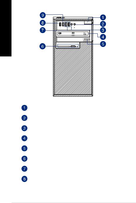
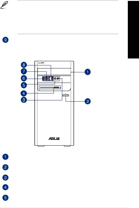
D540MA
Smart Card |
SD/MMC/MS |
Power button. Press this button to turn on your computer.
Microphone port. This Mic (pink) port connects a microphone.
Headphone port. This Line In (lime) port connects a headphone with a stereo miniplug.
Optical disk drive (optional). This optical disk drive reads or writes data to or from optical discs.
Optical disk drive eject button (optional). Press this button to eject the optical disk drive tray.
Memory card readers (optional). This area contains one or more memory card reader slots.
USB 2.0 ports. These Universal Serial Bus 2.0 (USB 2.0) ports connect to USB 2.0 devices such as a mouse, printer, scanner, camera, PDA, and others.
USB 3.1 gen1 port. The Universal Serial Bus 3.1 gen1 (USB 3.1 gen1) port connects to USB 3.1 gen1 devices such as a mouse, printer, scanner, camera, PDA, and others.
14 |
Chapter 1: Getting started |
• DO NOT connect a keyboard / mouse to any USB 3.1 gen1 port when installingWindows®
operating system.
•Due to USB 3.1 gen1 controller limitations, USB 3.1 gen1 devices can only be used under a
Windows® OS environment and after USB 3.1 gen1 driver installation.
•USB 3.1 gen1 devices can only be used as data storage only.
•We strongly recommend that you connect USB 3.1 gen1 devices to USB 3.1 gen1 ports for faster and better performance for your USB 3.1 gen1 devices.
USB 3.1 gen1 or Type-C port (only for data transfer). The Universal Serial Bus 3.1 gen1 (USB 3.1 gen1) or Type-C port connects to USB 3.1 gen1 or Type-C devices such as a mouse, printer, scanner, camera, PDA, and others.
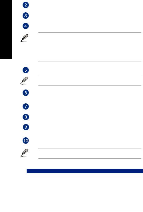
D540MB
Smart Card |
SD/MMC/MS |
<![endif]>ENGLISH
5.25 inch optical disk drive bay. The 5.25 inch optical disk drive bay is for 5.25 inch DVD-ROM / CD-RW / DVD-RW devices.
Power button. Press this button to turn on your computer.
Microphone port. This Mic (pink) port connects a microphone.
Memory card readers (optional). This area contains one or more memory card reader slots.
Headphone port. This Line In (lime) port connects a headphone with a stereo miniplug.
ASUS Desktop PC |
15 |
<![endif]>ENGLISH
USB 3.1 gen1 port. The Universal Serial Bus 3.1 gen1 (USB 3.1 gen1) port connects to USB 3.1 gen1 devices such as a mouse, printer, scanner, camera, PDA, and others.
• DO NOT connect a keyboard / mouse to any USB 3.1 gen1 port when installingWindows®
operating system.
•Due to USB 3.1 gen1 controller limitations, USB 3.1 gen1 devices can only be used under a
Windows® OS environment and after USB 3.1 gen1 driver installation.
•USB 3.1 gen1 devices can only be used as data storage only.
•We strongly recommend that you connect USB 3.1 gen1 devices to USB 3.1 gen1 ports for faster and better performance for your USB 3.1 gen1 devices.
USB 3.1 gen1 or Type-C port (only for data transfer). The Universal Serial Bus 3.1 gen1 (USB 3.1 gen1) or Type-C port connects to USB 3.1 gen1 or Type-C devices such as a mouse, printer, scanner, camera, PDA, and others.
USB 2.0 ports. These Universal Serial Bus 2.0 (USB 2.0) ports connect to USB 2.0 devices such as a mouse, printer, scanner, camera, PDA, and others.
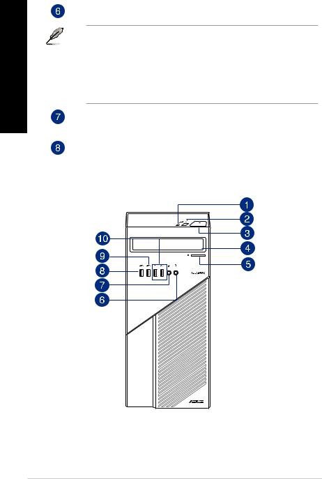
D540MC
16 |
Chapter 1: Getting started |

HDD LED.
On: HDD is ready.
Flashing: The HDD is transmitting or receiving data.
Reset button. Press this button to reset your computer.
Power button. Press this button to turn on your computer.
5.25 inch optical disk drive bay. The 5.25 inch optical disk drive bay is for 5.25 inch DVD-ROM / CD-RW / DVD-RW devices.
Optical disk drive eject button (optional). Press this button to eject the optical disk drive tray.
Headphone port. This Line In (lime) port connects a headphone with a stereo miniplug.
Microphone port. This Mic (pink) port connects a microphone.
USB 3.1 gen1 port. The Universal Serial Bus 3.1 gen1 (USB 3.1 gen1) port connects to USB 3.1 gen1 devices such as a mouse, printer, scanner, camera, PDA, and others.
•DO NOT connect a keyboard / mouse to any USB 3.1 gen1 port when installingWindows® operating system.
•Due to USB 3.1 gen1 controller limitations, USB 3.1 gen1 devices can only be used under a
Windows® OS environment and after USB 3.1 gen1 driver installation.
•USB 3.1 gen1 devices can only be used as data storage only.
•We strongly recommend that you connect USB 3.1 gen1 devices to USB 3.1 gen1 ports for faster and better performance for your USB 3.1 gen1 devices.
USB 3.1 gen1 or Type-C port (only for data transfer). The Universal Serial Bus 3.1 gen1 (USB 3.1 gen1) or Type-C port connects to USB 3.1 gen1 or Type-C devices such as a mouse, printer, scanner, camera, PDA, and others.
USB 2.0 ports. These Universal Serial Bus 2.0 (USB 2.0) ports connect to USB 2.0 devices such as a mouse, printer, scanner, camera, PDA, and others.
<![endif]>ENGLISH
ASUS Desktop PC |
17 |
<![endif]>ENGLISH
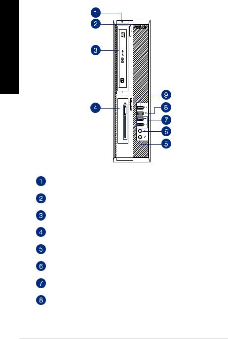
D540SA
| <![if ! IE]> <![endif]>SD/MMC/MS |
| <![if ! IE]> <![endif]>Smart Card |
Power button. Press this button to turn on your computer.
Optical disk drive eject button (optional). Press this button to eject the optical disk drive tray.
Optical disk drive (optional). This optical disk drive reads or writes data to or from optical discs.
Memory card readers (optional). This area contains one or more memory card reader slots.
Microphone port. This Mic (pink) port connects a microphone.
Headphone port. This Line In (lime) port connects a headphone with a stereo miniplug.
USB 2.0 ports. These Universal Serial Bus 2.0 (USB 2.0) ports connect to USB 2.0 devices such as a mouse, printer, scanner, camera, PDA, and others.
USB 3.1 gen1 or Type-C port (only for data transfer). The Universal Serial Bus 3.1 gen1 (USB 3.1 gen1) or Type-C port connects to USB 3.1 gen1 or Type-C devices such as a mouse, printer, scanner, camera, PDA, and others.
18 |
Chapter 1: Getting started |

USB 3.1 gen1 port. The Universal Serial Bus 3.1 gen1 (USB 3.1 gen1) port connects to USB 3.1 gen1 devices such as a mouse, printer, scanner, camera, PDA, and others.
• DO NOT connect a keyboard / mouse to any USB 3.1 gen1 port when installingWindows®
operating system.
•Due to USB 3.1 gen1 controller limitations, USB 3.1 gen1 devices can only be used under a
Windows® OS environment and after USB 3.1 gen1 driver installation.
•USB 3.1 gen1 devices can only be used as data storage only.
•We strongly recommend that you connect USB 3.1 gen1 devices to USB 3.1 gen1 ports for faster and better performance for your USB 3.1 gen1 devices.
Rear panel
D540MA
Power connector. Plug the power cord to this connector.
RATING: 115/230Vac, 50-60Hz, 6/3A or 220-230Vac, 50Hz, 3A or 230Vac, 50Hz, 3A or 100-120Vac, 50-60Hz, 8A
<![endif]>ENGLISH
ASUS Desktop PC |
19 |
<![endif]>ENGLISH
PS/2 mouse port (green). This port is for a PS/2 mouse.
PS/2 keyboard port (purple). This port is for a PS/2 keyboard.
USB 3.1 Gen 2 (up to 10Gbps) ports (teal blue, Type A). These 9-pin Universal Serial Bus 3.1 (USB 3.1) Gen 2 ports are for USB 3.1 Gen 2 devices.
• USB 3.1 Gen 2 / Gen 1 devices can only be used for data storage.
• Due to the design of the Intel® 300 series chipset, all USB devices connected to the USB 2.0 and USB 3.1 Gen 2 / Gen 1 ports are controlled by the xHCI controller. Some legacy USB devices must update their firmware for better compatibility.
•We strongly recommend that you connect USB 3.1 Gen 2 devices to USB 3.1 Gen 2 ports for faster and better performance from your USB 3.1 Gen 2 devices.
DVI-D port. This port is for any DVI-D compatible device.
DVI-D can not be converted to output from RGB Signal to CRT and is not compatible with DVI-I.
HDMI port. This port is for a High-Definition Multimedia Interface (HDMI) connector, and is HDCP compliant allowing playback of HD DVD, Blu-ray, and other protected content.
USB 2.0 ports. These Universal Serial Bus 2.0 (USB 2.0) ports connect to USB 2.0 devices such as a mouse, printer, scanner, camera, PDA, and others.
Microphone port (pink). This port connects a microphone.
Line Out port (lime). This port connects a headphone or a speaker. In 4.1-channel, 5.1-channel, and 7.1-channel configurations, the function of this port becomes Front Speaker Out.
Line In port (light blue). This port connects to a tape, CD, DVD player, or other audio sources.
Refer to the audio configuration table below for the function of the audio ports in a 2.1, 4.1, 5.1, or 7.1-channel configuration.
Audio 2.1, 4.1, 5.1, or 7.1-channel configuration
Port |
Headset 2.1-channel |
4.1-channel |
5.1-channel |
7.1-channel |
Light Blue (Rear panel) |
Line In |
Rear Speaker Out |
Rear Speaker Out |
Rear Speaker Out |
Lime (Rear panel) |
Line Out |
Front Speaker Out |
Front Speaker Out |
Front Speaker Out |
Pink (Rear panel) |
Mic In |
Mic In |
Bass/Center |
Bass/Center |
Front panel |
- |
- |
- |
Side Speaker Out |
20 |
Chapter 1: Getting started |
Expansion slot brackets. Remove the expansion slot bracket when installing an expansion card.
ASUS Graphics Card (on selected models only). The display output ports on this optional ASUS Graphics Card may vary with different models.
LAN (RJ-45) port. This port allows Gigabit connection to a Local Area Network (LAN) through a network hub.
|
LAN port LED indications |
|
ACT/LINK |
SPEED |
||||||||
|
|
LED |
LED |
|||||||||
|
Activity/Link LED |
|
Speed LED |
|
|
|
|
|
|
|
||
|
|
|
|
|
|
|
|
|
||||
|
|
|
|
|
|
|
|
|
|
|
|
|
|
Status |
|
Description |
|
Status |
Description |
|
|
|
|
|
|
|
OFF |
|
No link |
|
OFF |
10Mbps connection |
|
|
|
|
|
|
|
ORANGE |
|
Linked |
|
ORANGE |
100Mbps connection |
|
|
|
|
|
|
|
|
|
|
|
|
|
|
|
|
|
|
|
|
BLINKING |
Data activity |
|
GREEN |
1Gbps connection |
|
|
|
|
|
||
LAN port
Serial port. This COM port is for pointing devices or other serial devices.
Air vents. These vents allow air ventilation.
DO NOT block the air vents on the chassis. Always provide proper ventilation for your computer.
VGA port. This port is for VGA-compatible devices such as a VGA monitor.
Serial port (on selected models only). This COM port is for pointing devices or other serial devices.
LPT connector (on selected models only). Connect a parallel device such as a printer to this LPT (Line Printing Terminal) connector.
<![endif]>ENGLISH
ASUS Desktop PC |
21 |

D540MB
<![if ! IE]><![endif]>ENGLISH
Power switch. Switch to turn ON/OFF the power supply to your computer.
Power connector. Plug the power cord to this connector.
RATING: 115/230Vac, 50-60Hz, 6/3A or 220-230Vac, 50Hz, 3A or 230Vac, 50Hz, 3A or 100-120Vac, 50-60Hz, 8A
PS/2 mouse port (green). This port is for a PS/2 mouse.
PS/2 keyboard port (purple). This port is for a PS/2 keyboard.
USB 3.0 ports. These Universal Serial Bus 3.0 (USB 3.0) ports connect to USB 3.0 devices such as a mouse, printer, scanner, camera, PDA, and others.
•DO NOT connect a keyboard / mouse to any USB 3.0 port when installing aWindows® operating system.
•Windows® 7 requires USB 3.0 driver to be installed before using USB 3.0 devices.
•We strongly recommend that you connect USB 3.0 devices to USB 3.0 ports for a faster and better performance from your USB 3.0 devices.
22 |
Chapter 1: Getting started |

DVI-D port. This port is for any DVI-D compatible device.
DVI-D can not be converted to output from RGB Signal to CRT and is not compatible with DVI-I.
HDMI port. This port is for a High-Definition Multimedia Interface (HDMI) connector, and is HDCP compliant allowing playback of HD DVD, Blu-ray, and other protected content.
USB 2.0 ports. These Universal Serial Bus 2.0 (USB 2.0) ports connect to USB 2.0 devices such as a mouse, printer, scanner, camera, PDA, and others.
Microphone port (pink). This port connects a microphone.
Line Out port (lime). This port connects a headphone or a speaker. In 4.1-channel, 5.1-channel, and 7.1-channel configurations, the function of this port becomes Front Speaker Out.
Line In port (light blue). This port connects to a tape, CD, DVD player, or other audio sources.
Refer to the audio configuration table below for the function of the audio ports in a 2.1, 4.1, 5.1, or 7.1-channel configuration.
Audio 2.1, 4.1, 5.1, or 7.1-channel configuration
Port |
Headset 2.1-channel |
4.1-channel |
5.1-channel |
7.1-channel |
Light Blue (Rear panel) |
Line In |
Rear Speaker Out |
Rear Speaker Out |
Rear Speaker Out |
Lime (Rear panel) |
Line Out |
Front Speaker Out |
Front Speaker Out |
Front Speaker Out |
Pink (Rear panel) |
Mic In |
Mic In |
Bass/Center |
Bass/Center |
Front panel |
- |
- |
- |
Side Speaker Out |
Expansion slot brackets. Remove the expansion slot bracket when installing an expansion card.
ASUS Graphics Card (on selected models only). The display output ports on this optional ASUS Graphics Card may vary with different models.
LAN (RJ-45) port. This port allows Gigabit connection to a Local Area Network (LAN) through a network hub.
LAN port LED indications |
|
|
ACT/LINK |
SPEED |
||||||||||
|
|
LED |
LED |
|||||||||||
|
|
|
|
|
|
|
|
|||||||
|
|
|
|
|
|
|
|
|
|
|
|
|
|
|
|
Activity/Link LED |
|
Speed LED |
|
|
|
|
|
|
|
|
|
||
|
Status |
|
Description |
|
Status |
Description |
|
|
|
|
|
|
|
|
|
OFF |
|
No link |
|
OFF |
10Mbps connection |
|
|
|
|
|
|
|
|
|
|
|
|
|
|
|
|
|
||||||
|
ORANGE |
|
Linked |
|
ORANGE |
100Mbps connection |
|
|
|
|
|
|
|
|
|
BLINKING |
|
Data activity |
|
GREEN |
1Gbps connection |
|
|
|
|
|
|
|
|
|
|
|
|
|
|
|
|
|||||||
LAN port
<![endif]>ENGLISH
ASUS Desktop PC |
23 |

<![endif]>ENGLISH
Serial ports (on selected models only). These COM ports are for pointing devices or other serial devices.
LPT connector (on selected models only). Connect a parallel device such as a printer to this LPT (Line Printing Terminal) connector.
Serial port. This COM port is for pointing devices or other serial devices.
Air vents. These vents allow air ventilation.
DO NOT block the air vents on the chassis. Always provide proper ventilation for your computer.
VGA port. This port is for VGA-compatible devices such as a VGA monitor.
D540MC
Power connector. Plug the power cord to this connector.
RATING: 115/230Vac, 50-60Hz, 6/3A or 220-230Vac, 50Hz, 3A or 230Vac, 50Hz, 3A or 100-120Vac, 50-60Hz, 8A
24 |
Chapter 1: Getting started |
PS/2 mouse port (green). This port is for a PS/2 mouse.
PS/2 keyboard port (purple). This port is for a PS/2 keyboard.
USB 3.0 ports. These Universal Serial Bus 3.0 (USB 3.0) ports connect to USB 3.0 devices such as a mouse, printer, scanner, camera, PDA, and others.
• DO NOT connect a keyboard / mouse to any USB 3.0 port when installing aWindows®
operating system.
•Windows® 7 requires USB 3.0 driver to be installed before using USB 3.0 devices.
•We strongly recommend that you connect USB 3.0 devices to USB 3.0 ports for a faster and better performance from your USB 3.0 devices.
DVI-D port. This port is for any DVI-D compatible device.
DVI-D can not be converted to output from RGB Signal to CRT and is not compatible with DVI-I.
HDMI port. This port is for a High-Definition Multimedia Interface (HDMI) connector, and is HDCP compliant allowing playback of HD DVD, Blu-ray, and other protected content.
USB 2.0 ports. These Universal Serial Bus 2.0 (USB 2.0) ports connect to USB 2.0 devices such as a mouse, printer, scanner, camera, PDA, and others.
Microphone port (pink). This port connects a microphone.
Line Out port (lime). This port connects a headphone or a speaker. In 4.1-channel, 5.1-channel, and 7.1-channel configurations, the function of this port becomes Front Speaker Out.
Line In port (light blue). This port connects to a tape, CD, DVD player, or other audio sources.
Refer to the audio configuration table below for the function of the audio ports in a 2.1, 4.1, 5.1, or 7.1-channel configuration.
Audio 2.1, 4.1, 5.1, or 7.1-channel configuration
Port |
Headset 2.1-channel |
4.1-channel |
5.1-channel |
7.1-channel |
Light Blue (Rear panel) |
Line In |
Rear Speaker Out |
Rear Speaker Out |
Rear Speaker Out |
Lime (Rear panel) |
Line Out |
Front Speaker Out |
Front Speaker Out |
Front Speaker Out |
Pink (Rear panel) |
Mic In |
Mic In |
Bass/Center |
Bass/Center |
Front panel |
- |
- |
- |
Side Speaker Out |
Expansion slot brackets. Remove the expansion slot bracket when installing an expansion card.
ASUS Graphics Card (on selected models only). The display output ports on this optional ASUS Graphics Card may vary with different models.
<![endif]>ENGLISH
ASUS Desktop PC |
25 |

<![endif]>ENGLISH
LAN (RJ-45) port. This port allows Gigabit connection to a Local Area Network (LAN) through a network hub.
LAN port LED indications |
|
|
ACT/LINK |
SPEED |
|||||||||||
|
|
LED |
LED |
||||||||||||
|
|
|
|
|
|
|
|
|
|||||||
|
|
|
|
|
|
|
|
|
|
|
|
|
|
|
|
|
|
Activity/Link LED |
|
Speed LED |
|
|
|
|
|
|
|
|
|
||
|
|
Status |
|
Description |
|
Status |
Description |
|
|
|
|
|
|
|
|
|
|
OFF |
|
No link |
|
OFF |
10Mbps connection |
|
|
|
|
|
|
|
|
|
|
|
|
|
|
|
|
|
|
||||||
|
|
ORANGE |
|
Linked |
|
ORANGE |
100Mbps connection |
|
|
|
|
|
|
|
|
|
|
BLINKING |
|
Data activity |
|
GREEN |
1Gbps connection |
|
|
|
|
|
|
|
|
|
|
|
|
|
|
|
|
|
|||||||
LAN port
LPT connector (on selected models only). Connect a parallel device such as a printer to this LPT (Line Printing Terminal) connector.
Serial ports (on selected models only). These COM ports are for pointing devices or other serial devices.
Serial port. This COM port is for pointing devices or other serial devices.
Air vents. These vents allow air ventilation.
DO NOT block the air vents on the chassis. Always provide proper ventilation for your computer.
VGA port. This port is for VGA-compatible devices such as a VGA monitor.
26 |
Chapter 1: Getting started |

D540SA
<![if ! IE]><![endif]>ENGLISH
PS/2 mouse port (green). This port is for a PS/2 mouse.
PS/2 keyboard port (purple). This port is for a PS/2 keyboard.
USB 3.1 Gen 2 (up to 10Gbps) ports (teal blue, Type A). These 9-pin Universal Serial Bus 3.1 (USB 3.1) Gen 2 ports are for USB 3.1 Gen 2 devices.
•USB 3.1 Gen 2 / Gen 1 devices can only be used for data storage.
•Due to the design of the Intel® 300 series chipset, all USB devices connected to the USB 2.0 and USB 3.1 Gen 2 / Gen 1 ports are controlled by the xHCI controller. Some legacy USB devices must update their firmware for better compatibility.
•We strongly recommend that you connect USB 3.1 Gen 2 devices to USB 3.1 Gen 2 ports for faster and better performance from your USB 3.1 Gen 2 devices.
DVI-D port. This port is for any DVI-D compatible device.
DVI-D can not be converted to output from RGB Signal to CRT and is not compatible with
DVI-I.
HDMI port. This port is for a High-Definition Multimedia Interface (HDMI) connector, and is HDCP compliant allowing playback of HD DVD, Blu-ray, and other protected content.
ASUS Desktop PC |
27 |

<![endif]>ENGLISH
USB 2.0 ports. These Universal Serial Bus 2.0 (USB 2.0) ports connect to USB 2.0 devices such as a mouse, printer, scanner, camera, PDA, and others.
Microphone port (pink). This port connects a microphone.
Line Out port (lime). This port connects a headphone or a speaker. In 4.1-channel, 5.1-channel, and 7.1-channel configurations, the function of this port becomes Front Speaker Out.
Line In port (light blue). This port connects to a tape, CD, DVD player, or other audio sources.
Refer to the audio configuration table below for the function of the audio ports in a 2.1, 4.1, 5.1, or 7.1-channel configuration.
Audio 2.1, 4.1, 5.1, or 7.1-channel configuration
Port |
Headset 2.1-channel |
4.1-channel |
5.1-channel |
7.1-channel |
Light Blue (Rear panel) |
Line In |
Rear Speaker Out |
Rear Speaker Out |
Rear Speaker Out |
Lime (Rear panel) |
Line Out |
Front Speaker Out |
Front Speaker Out |
Front Speaker Out |
Pink (Rear panel) |
Mic In |
Mic In |
Bass/Center |
Bass/Center |
Front panel |
- |
- |
- |
Side Speaker Out |
Air vents. These vents allow air ventilation.
DO NOT block the air vents on the chassis. Always provide proper ventilation for your computer.
Power connector. Plug the power cord to this connector.
RATING: 115/230Vac, 50-60Hz, 6/3A or
220-230Vac, 50Hz, 3A
Expansion slot brackets. Remove the expansion slot bracket when installing an expansion card.
ASUS WLAN Card (on selected models only). This optional WLAN card allows your computer to connect to a wireless network.
LPT connectors (on selected models only). Connect a parallel device such as a printer to these LPT (Line Printing Terminal) connectors.
LAN (RJ-45) port. This port allows Gigabit connection to a Local Area Network (LAN) through a network hub.
LAN port LED indications |
|
ACT/LINK |
SPEED |
||||||||
|
LED |
LED |
|||||||||
|
Activity/Link LED |
|
Speed LED |
|
|
|
|
|
|
||
|
Status |
|
Description |
|
Status |
Description |
|
|
|
|
|
|
OFF |
|
No link |
|
OFF |
10Mbps connection |
|
|
|
|
|
|
|
|
|
|
|
|
|
||||
|
|
|
|
|
|
|
|
||||
|
ORANGE |
|
Linked |
|
ORANGE |
100Mbps connection |
|
|
|
|
|
|
BLINKING |
|
Data activity |
|
GREEN |
1Gbps connection |
|
|
|
|
|
|
|
|
|
|
|
|
|
LAN port |
|
||
|
|
|
|
|
|
|
|
||||
|
|
|
|
|
|
|
|
||||
28 |
|
|
|
|
|
|
Chapter 1: Getting started |
||||

Serial port. This COM port is for pointing devices or other serial devices.
Serial port (on selected models only). This COM port is for pointing devices or other serial devices.
VGA port. This port is for VGA-compatible devices such as a VGA monitor.
Setting up your computer
This section guides you through connecting the main hardware devices, such as the external monitor, keyboard, mouse, and power cord, to your computer.
Connecting an external monitor
Using the ASUS Graphics Card (on selected models only)
Connect your monitor to the display output port on the discrete ASUS Graphics Card.
To connect an external monitor using the ASUS Graphics Card:
1.Connect a monitor to a display output port on the ASUS Graphics Card.
2.Plug the monitor to a power source.
The display output ports on the ASUS Graphics Card may vary with different models.
D540MA
<![endif]>ENGLISH
|
|
|
|
|
|
|
|
|
|
|
|
|
|
|
|
|
|
|
|
|
|
|
|
|
|
|
|
|
|
|
|
|
|
|
|
|
|
|
|
|
|
|
|
|
|
|
|
|
|
|
|
|
|
|
|
|
|
|
|
|
|
|
|
|
|
|
|
|
|
|
|
|
|
|
|
|
|
|
|
|
|
|
|
|
|
|
|
|
|
ASUS Desktop PC |
29 |
|||||||

<![endif]>ENGLISH
Using the onboard display output ports
Connect your monitor to the onboard display output port.
To connect an external monitor using the onboard display output ports:
1.Connect a VGA monitor to the VGA port or a DVI-D monitor to the DVI-D port on the rear panel of your computer.
2.Plug the monitor to a power source.
D540MA |
|
D540MB |
|
|
|
||||||||||||||
|
|
|
|
|
|
|
|
|
|
|
|
|
|
|
|
|
|
|
|
|
|
|
|
|
|
|
|
|
|
|
|
|
|
|
|
|
|
|
|
|
|
|
|
|
|
|
|
|
|
|
|
|
|
|
|
|
|
|
|
|
|
|
|
|
|
|
|
|
|
|
|
|
|
|
|
|
|
|
|
|
|
|
|
|
|
|
|
|
|
|
|
|
|
|
|
|
|
|
|
|
|
|
|
|
|
|
|
|
|
|
|
|
|
|
|
|
|
|
|
|
|
|
|
|
|
|
|
|
|
|
|
|
|
|
|
|
|
|
|
|
|
|
|
|
|
|
|
|
|
|
|
|
|
|
|
|
|
|
|
|
|
|
|
|
|
|
|
|
|
|
|
|
|
|
|
|
|
|
|
|
|
|
|
|
|
|
|
|
|
|
|
|
|
|
|
|
|
|
|
|
|
|
|
|
|
|
|
|
|
|
|
|
|
|
|
|
|
|
|
D540MC |
|
D540SA |
|||||||||||||
|
|
|
|
|
|
|
|
|
|
|
|
|
|
|
|
|
|
|
|
|
|
|
|
|
|
|
|
|
|
|
|
|
|
|
|
|
|
|
|
|
|
|
|
|
|
|
|
|
|
|
|
|
|
|
|
|
|
|
|
|
|
|
|
|
|
|
|
|
|
|
|
|
|
|
|
|
|
|
|
|
|
|
|
|
|
|
|
|
|
|
|
|
|
|
|
|
|
|
|
|
|
|
|
|
|
|
|
|
|
|
|
|
|
|
|
|
|
|
|
|
|
|
|
|
|
|
|
|
|
|
|
|
|
|
|
|
|
|
|
|
|
|
|
|
|
|
|
|
|
|
|
|
|
|
|
|
|
|
|
|
|
|
|
|
|
|
|
|
|
|
|
|
|
|
|
DVI
• If your computer comes with an ASUS Graphics Card, the graphics card is set as the primary display device in the BIOS. Hence, connect your monitor to a display output port on the graphics card.
•To connect multiple external monitors to your computer, refer to Connecting multiple external display in Chapter 2 of this guide for details.
30 |
Chapter 1: Getting started |
Loading...