


E1469 DIGIMATRIX AB
Digital Entertainment PC
AB-V10
®
DiGiMatrix
User Guide

ii
User Guide
Copyright © 2003 ASUSTeK COMPUTER INC. All Rights Reserved.
No part of this manual, including the products and software described in it, may be
reproduced, transmitted, transcribed, stored in a retrieval system, or translated into any
language in any form or by any means, except documentation kept by the purchaser for
backup purposes, without the express written permission of ASUSTeK COMPUTER INC.
(“ASUS”).
Product warranty or service will not be extended if: (1) the product is repaired, modified or
altered, unless such repair, modification of alteration is authorized in writing by ASUS; or (2)
the serial number of the product is defaced or missing.
ASUS PROVIDES THIS MANUAL “AS IS” WITHOUT WARRANTY OF ANY KIND, EITHER
EXPRESS OR IMPLIED, INCLUDING BUT NOT LIMITED TO THE IMPLIED WARRANTIES
OR CONDITIONS OF MERCHANTABILITY OR FITNESS FOR A PARTICULAR PURPOSE.
IN NO EVENT SHALL ASUS, ITS DIRECTORS, OFFICERS, EMPLOYEES OR AGENTS BE
LIABLE FOR ANY INDIRECT, SPECIAL, INCIDENTAL, OR CONSEQUENTIAL DAMAGES
(INCLUDING DAMAGES FOR LOSS OF PROFITS, LOSS OF BUSINESS, LOSS OF USE
OR DATA, INTERRUPTION OF BUSINESS AND THE LIKE), EVEN IF ASUS HAS BEEN
ADVISED OF THE POSSIBILITY OF SUCH DAMAGES ARISING FROM ANY DEFECT OR
ERROR IN THIS MANUAL OR PRODUCT.
SPECIFICATIONS AND INFORMATION CONTAINED IN THIS MANUAL ARE FURNISHED
FOR INFORMATIONAL USE ONLY, AND ARE SUBJECT TO CHANGE AT ANY TIME
WITHOUT NOTICE, AND SHOULD NOT BE CONSTRUED AS A COMMITMENT BY ASUS.
ASUS ASSUMES NO RESPONSIBILITY OR LIABILITY FOR ANY ERRORS OR
INACCURACIES THAT MAY APPEAR IN THIS MANUAL, INCLUDING THE PRODUCTS
AND SOFTWARE DESCRIBED IN IT.
Products and corporate names appearing in this manual may or may not be registered
trademarks or copyrights of their respective companies, and are used only for identification or
explanation and to the owners’ benefit, without intent to infringe.
E1469
Revised Edition V3
November 2003

iii
ASUS DiGiMatrix
Table of contents
Notices ...........................................................................................vi
Safety information ......................................................................... vii
About this guide............................................................................ viii
System package contents ...............................................................x
Chapter 1: System Introduction
1.1 Welcome! ........................................................................... 1-2
1.2 Front panel (external) ......................................................... 1-2
1.3 Front panel (internal) .......................................................... 1-4
1.4 Rear panel.......................................................................... 1-6
1.5 Internal components........................................................... 1-7
1.6 LED panel........................................................................... 1-8
Chapter 2: Basic Installation
2.1 Preparation......................................................................... 2-2
2.2 Before you proceed ............................................................ 2-2
2.3 Removing the top cover ..................................................... 2-3
2.4 Installing a hard disk drive.................................................. 2-4
2.5 Installing a CPU.................................................................. 2-6
2.6 Installing a DIMM................................................................ 2-9
2.7 Replacing the top cover.................................................... 2-10
2.8 Connecting cables.............................................................2-11
2.8.1 Power adapter and cable ....................................2-11
2.8.2 Radio antenna.................................................... 2-12
2.8.3 Audio/Video cable .............................................. 2-12
2.8.4 Video out cable .................................................. 2-12
2.8.5 HDTV cable........................................................ 2-13
2.8.6 Audio out cable .................................................. 2-13
2.9 Connecting external devices ............................................ 2-14
Chapter 3: Starting up
3.1 Installing an operating system............................................ 3-2
3.2 Powering up ....................................................................... 3-2

iv
User Guide
3.3 Support CD information...................................................... 3-2
3.3.1 Running the support CD....................................... 3-3
3.3.2 Drivers menu........................................................ 3-3
3.3.3 Utilities menu........................................................ 3-5
3.3.4 ASUS contact information .................................... 3-6
3.3.5 Other information ................................................. 3-6
3.4 Software information .......................................................... 3-7
3.4.1 ASUS Update....................................................... 3-7
3.4.2 ASUS PC Probe................................................... 3-9
3.4.3 Multi-channel audio feature................................ 3-13
3.4.4 Music Wizard...................................................... 3-16
3.5 Audio DJ........................................................................... 3-19
3.5.1 Selecting an audio source.................................. 3-20
3.5.2 Playing MP3 files from the hard disk drive ......... 3-20
3.5.3 Playing an audio CD/DVD.................................. 3-20
3.5.4 Tuning into an FM radio station.......................... 3-21
3.5.5 Presetting a station ............................................ 3-21
3.5.6 Adjusting the volume.......................................... 3-21
3.6 ASUS Home Theater........................................................ 3-22
3.6.1 Installing ASUS Home Theater .......................... 3-22
3.6.2 Using ASUS Home Theater ............................... 3-24
5.6.3 Entertainment modes ......................................... 3-26
3.7 ASUS Wireless LAN adapter............................................ 3-35
3.7.1 Installing the WLAN Card utilities and driver...... 3-36
3.7.2 Setting the Windows® XP wireless options ....... 3-36
3.7.3 Other support CD options .................................. 3-36
3.7.4 Setup Wizard...................................................... 3-37
3.7.5 The Control Center utility ................................... 3-50
3.7.6 Configuring the wireless LAN adapter by
Wireless Settings utility ...................................... 3-60
Chapter 4: Motherboard Information
4.1 Introduction......................................................................... 4-2
4.2 Motherboard components .................................................. 4-2
4.3 Motherboard layout ............................................................ 4-5
Table of contents

v
ASUS DiGiMatrix
4.4 Central Processing Unit (CPU)........................................... 4-6
4.5 System memory ................................................................. 4-7
4.6 Jumper ............................................................................... 4-8
4.7 Connectors ......................................................................... 4-9
Chapter 5: BIOS information
5.1 Managing and updating your BIOS .................................... 5-2
5.2 BIOS Setup program .......................................................... 5-4
5.2.1 BIOS menu bar .................................................... 5-5
5.2.2 Legend bar ........................................................... 5-5
5.3 Main menu.......................................................................... 5-7
5.3.1 Primary and Secondary Master/Slave.................. 5-9
5.3.2 Keyboard Features............................................. 5-13
5.4 Advanced menu ............................................................... 5-14
5.4.1 Chip Configuration ............................................. 5-16
5.4.2 PCI Configuration............................................... 5-17
5.5 Power menu ..................................................................... 5-21
5.5.1 Power Up Control............................................... 5-23
5.5.2 Hardware Monitor............................................... 5-24
5.6 Boot menu ........................................................................ 5-25
5.7 Exit menu ......................................................................... 5-27
Appendix
A.1 Subsystem..........................................................................A-2
A.1.1 Front and rear panel features...............................A-2
A.1.2 Removing the top cover .......................................A-3
A.1.3 Installing a hard disk drive....................................A-3
A.1.4 Connecting the Subsystem to DiGiMatrix ............A-4
A.2 DiGiMatrix remote controller...............................................A-5
A.2.1 Specifications .......................................................A-5
A.2.2 Remote control layout .......................................... A-5
A.2.3 Remote control functions in Audio DJ .................. A-6
A.2.4 Remote control functions in Home Theater..........A-7
A.3 Optical drive technical specifications..................................A-9
A.4 Wireless LAN adapter channels ....................................... A-10
Table of contents

vi
User Guide
Notices
Federal Communications Commission Statement
This device complies with FCC Rules Part 15. Operation is subject to the
following two conditions:
• This device may not cause harmful interference, and
• This device must accept any interference received including
interference that may cause undesired operation.
This equipment has been tested and found to comply with the limits for a
Class B digital device, pursuant to Part 15 of the FCC Rules. These limits
are designed to provide reasonable protection against harmful interference
in a residential installation. This equipment generates, uses and can
radiate radio frequency energy and, if not installed and used in
accordance with manufacturer’s instructions, may cause harmful
interference to radio communications. However , there is no guarantee that
interference will not occur in a particular installation. If this equipment does
cause harmful interference to radio or television reception, which can be
determined by turning the equipment off and on, the user is encouraged to
try to correct the interference by one or more of the following measures:
• Reorient or relocate the receiving antenna.
• Increase the separation between the equipment and receiver.
• Connect the equipment to an outlet on a circuit different from that to
which the receiver is connected.
• Consult the dealer or an experienced radio/TV technician for help.
Canadian Department of Communications Statement
This digital apparatus does not exceed the Class B limits for radio noise
emissions from digital apparatus set out in the Radio Interference
Regulations of the Canadian Department of Communications.
This class B digital apparatus complies with Canadian ICES-003.
WARNING!
The use of shielded cables for connection of the monitor to the graphics
card is required to assure compliance with FCC regulations. Changes or
modifications to this unit not expressly approved by the party responsible
for compliance could void the user’s authority to operate this equipment.

vii
ASUS DiGiMatrix
Safety information
Electrical safety
• To prevent electrical shock hazard, disconnect the power cable from
the electrical outlet before relocating the system.
• When adding or removing devices to or from the system, ensure that
the power cables for the devices are unplugged before the signal
cables are connected.
• If the power supply is broken, do not try to fix it by yourself. Contact a
qualified service technician or your retailer.
Operation safety
• Before installing devices into the system, carefully read all the
documentation that came with the package.
• Before using the product, make sure all cables are correctly
connected and the power cables are not damaged. If you detect any
damage, contact your dealer immediately.
• To avoid short circuits, keep paper clips, screws, and staples away
from connectors, slots, sockets and circuitry.
• Avoid dust, humidity, and temperature extremes. Do not place the
product in any area where it may become wet. Place the product on a
stable surface.
• If you encounter technical problems with the product, contact a
qualified service technician or your retailer.
Lithium-Ion Battery Warning
CAUTION: Danger of explosion if battery is incorrectly replaced.
Replace only with the same or equivalent type recommended by
the manufacturer. Dispose of used batteries according to the
manufacturerís instructions.
VORSICHT: Explosionsgetahr bei unsachgemäßen Austausch der
Batterie. Ersatz nur durch denselben oder einem vom Hersteller
empfohlenem ähnljchen Typ. Entsorgung gebrauchter Batterien
nach Angaben des Herstellers.
LASER PRODUCT WARNING
CLASS 1 LASER PRODUCT

viii
User Guide
Safeguards
About this guide
Audience
This guide provides general information and installation instructions about
the ASUS DiGiMatrix. This guide is intended for experienced users and
integrators with hardware knowledge of personal computers.
How this guide is organized
This guide contains the following chapters:
1. Chapter 1: System Introduction
This chapter gives a general description of the ASUS DiGiMatrix. The
chapter lists the system features including introduction on the front
and rear panel, and internal components.
2. Chapter 2: Basic Installation
This chapter provides step-by-step instructions on how to install
components in the ASUS DiGiMatrix system.
3. Chapter 3: Starting up
This chapter helps you power up the system and install drivers and
utilities from the support CD.
4. Chapter 4: Motherboard Information
This chapter gives information about the P4SQ motherboard that
came with the system. This chapter includes the motherboard layout,
jumper settings, and connector locations.
5. Chapter 5: BIOS information
This chapter tells how to change system settings through the BIOS
Setup menus and describes the BIOS parameters.
6. Appendix
The Appendix provides information on the DiGiMatrix Subsystem,
remote controller, optical drive technical specifications, and IEEE
802.11b channels for the wireless LAN adapter.

ix
ASUS DiGiMatrix
Conventions used in this guide
WARNING: Information to prevent injury to yourself when trying to
complete a task.
CAUTION: Information to prevent damage to the components
when trying to complete a task.
IMPORTANT: Information that you MUST follow to complete a task.
NOTE: Tips and additional information to aid in completing a task.
Where to find more information
Refer to the following sources for additional information and for product
and software updates.
1. ASUS websites
The ASUS websites worldwide provide updated information on ASUS
hardware and software products. Refer to the ASUS contact
information.
2. Optional documentation
Your product package may include optional documentation, such as
warranty flyers, that may have been added by your dealer. These
documents are not part of the standard package.

x
User Guide
System package contents
If any of the above items is damaged or missing, contact your retailer
immediately.
Check your ASUS DiGiMatrix package for the following items.
1. ASUS DiGiMatrix Digital Entertainment System with
• ASUS P4SQ motherboard
• DVD-ROM/CD-RW/DVD-RW drive
• 7-in-1 storage card reader
2. Cables
• Universal power adapter and cable (100V-240V)
• HDTV cable
• Audio/video cable
• Video out cable
• Audio out cable
3. Accessories
• Radio antenna
• Remote controller
4. DiGiMatrix support CD
5. User Guide

ASUS DiGiMatrix
Chapter 1
System Introduction
This chapter gives a general description of
the ASUS DiGiMatrix. The chapter lists the
system features including introduction on the
front and rear panel, and internal
components.
1-2
Chapter 1: System Introduction
1.1 Welcome!
Thank you for choosing the ASUS DiGiMatrix!
The ASUS DiGiMatrix is a smart personal computer and a versatile home
entertainment system in one. Powered by the ASUS P4SQ motherboard,
DiGiMatrix delivers the cutting edge technology for your computing and
multimedia entertainment needs. DiGiMatrix comes with a slim optical
drive, TV and FM tuner, 4-slot card reader, wireless LAN adapter, and
6-channel digital audio in a compact and stylish casing.
DiGiMatrix supports the latest Intel
®
Pentium
®
4/Celeron processor with up
to 2.4GHz core frequencies and up to 2GB of system memory. Providing
the best connectivity for external devices and peripherals are eight (8)
USB 2.0 ports, fast Ethernet and Gigabit LAN ports, IEEE 1394 port, and
S/PDIF interface. The DiGiMatrix includes an IEEE 802.11b compliant
wireless network adapter to support your wireless networking needs.
The DiGiMatrix features the most silent multimedia system to give you
pure acoustic enjoyment. With the ASUS DiGiMatrix, you don’t need
anything else!
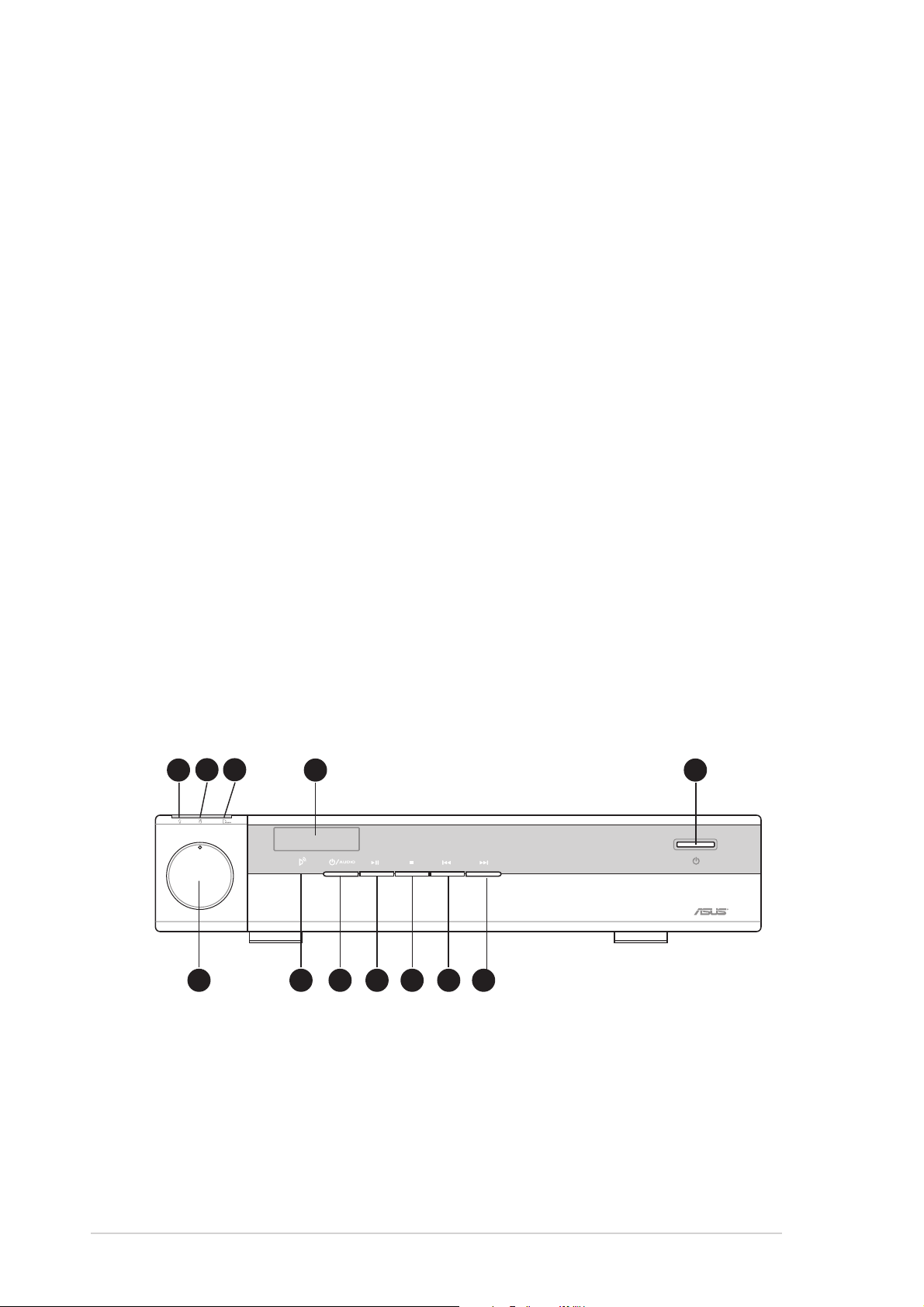
1.2 Front panel (external)
The DiGiMatrix front panel includes the system and audio control buttons,
system LEDs, and LED panel.
— VOLUME +
1
2 3
4 5
6 7 8 9 10 11 12
1. Power LED. When lit, this LED indicates that the system is ON.
2. HDD LED. This LED lights up when data is being read from or written
to the hard disk drive.
3. Card LED. This LED lights up when data is being read from or written
to a storage card inserted in any of the card reader slots.

1-3
ASUS DiGiMatrix
4. LED panel. The LED panel displays the audio medium (HD/CD/FM),
radio frequency, player status ( / ), real time clock, track number and
time, and CPU temperature. See page 1-8 for details.
5. System power button. Press this button to turn the system on and
enter the DiGiMatrix operating system.
6. System volume dial. Turn this dial clockwise to increase the system
volume or counterclockwise to decrease the system volume. In Audio
DJ mode, press the system volume dial to mute sound.
7. Remote sensor. This sensor receives signals from the DiGiMatrix
remote controller. See page A-5 for details on the remote controller.
8. Audio DJ power button. Press this button to turn on the DiGiMatrix
Audio DJ. The Audio DJ feature allows you to play CD/DVD audio
tracks and MP3 files on your hard disk drive, or tune into an FM radio
station without entering the DiGiMatrix operating system. See page
3-19 for details.
9. PLAY/PAUSE button. Press this button to perform various functions in
different modes.
In CD mode, plays the first track of the audio CD/DVD in the optical
drive. When playing an audio track, pauses the track being played.
In Hard Disk (HD) mode, plays the first MP3 file of a selected playlist.
When playing an audio track/file, pauses the track/file being played.
In Radio mode, scans the available FM stations.
10. STOP button. Press this button to perform various functions in
different modes.
In CD/HD mode, (pressed once) stops the audio track/file being
played, or (pressed twice) sets the Audio DJ in Playlist mode.
In Radio mode, sets the Audio DJ in Playlist mode.
11. PREVIOUS button. Press this button to perform various functions in
different modes.
In CD/HD mode, selects the previous audio track/file.
In Radio mode, selects the previous preset station.
In Playlist mode, selects the previous available audio source.
The following front panel buttons are activated only when DiGiMatrix is in
Audio DJ mode.
1-4
Chapter 1: System Introduction
FRONT PANEL (OPEN)
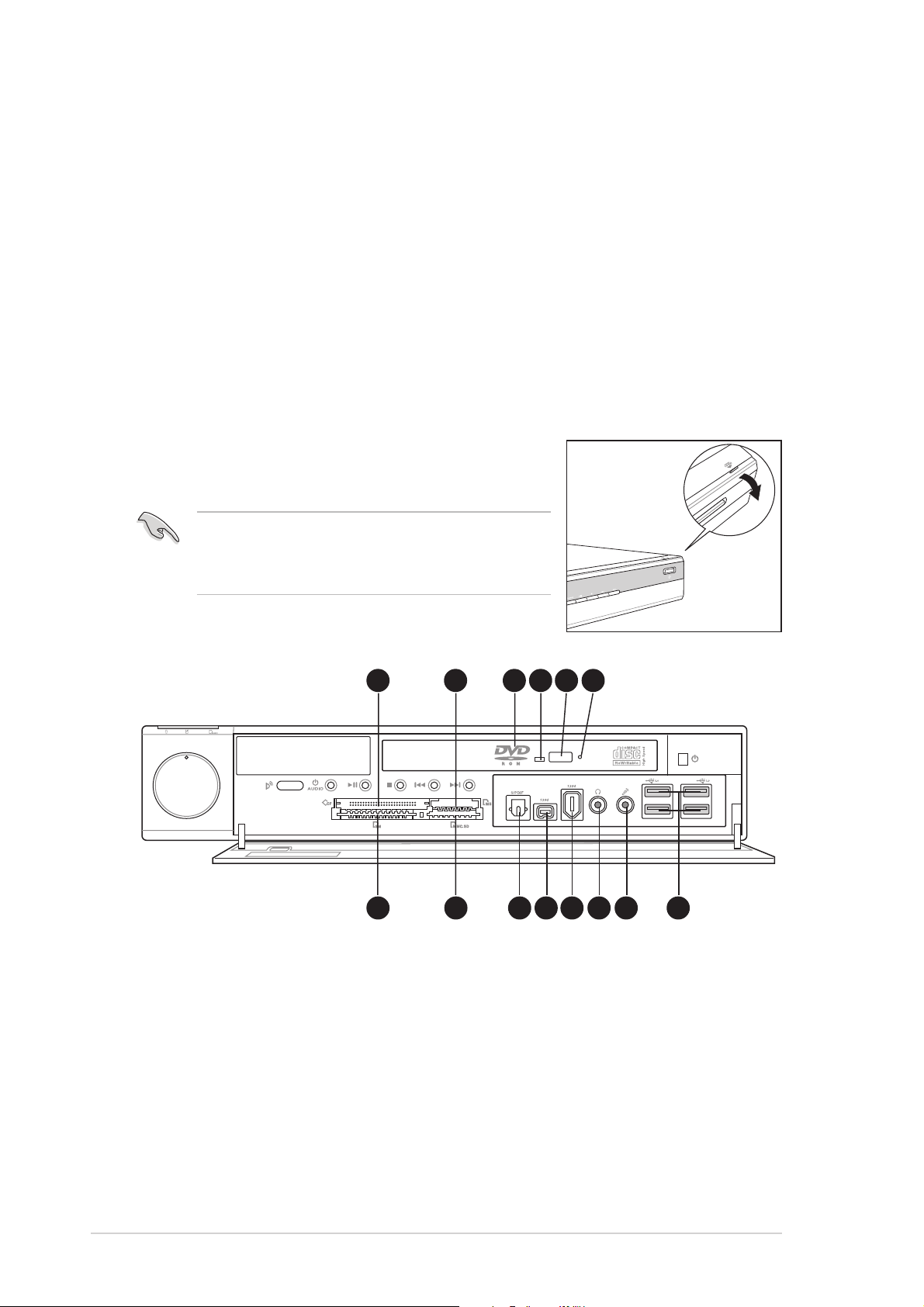
1.3 Front panel (internal)
The optical drive, storage card slots, and several I/O ports are located
inside the front panel door.
Flip down the front panel door to open. Refer to
the illustration on the right.
— VOLUME +
13 14 15 16 17 18
19 20 21 22 23 24 25 26
You can not close the front panel door if a
flash memory card is inserted into any of the
card slots.
12. NEXT button. Press this button to perform various functions in
different modes.
In CD/HD mode, selects the next audio track/file.
In Radio mode, selects the next preset station.
In Playlist mode, selects the next available audio source.
13. CompactFlash
®
/Microdrive™ card slot. This slot is for a
CompactFlash
®
/Microdrive™ storage card.
14. Memory Stick
®
/Memory Stick Pro™ card slot. This slot is for a
Memory Stick
®
/Memory Stick Pro™ storage card.
15. Optical drive. This is a slim DVD-ROM/CD-RW/DVD-RW drive.

1-5
ASUS DiGiMatrix
16. Drive activity LED. This LED lights up when you place a disc on the
drive tray, and turns off when you remove the disc. The LED flashes
when data is being read from or written to the disc.
17. STOP/EJECT button. Press this button to eject the disc loading tray.
18. Emergency eject pinhole. The emergency eject pinhole allows you
to manually eject a disc when the STOP button does not work due to
power failure or software problems. Insert the emergency eject pin or
a paper clip into this hole to manually eject the tray and the disc.
19. SmartMedia
®
card slot. This slot is for a SmartMedia
®
storage card.
20. Secure Digital™/MultimediaCard slot. This slot is for a Secure
Digital™/MultimediaCard storage card.
21. Optical S/PDIF port. This port connects your audio system for
5.1-channel surround sound and enhanced 3D audio.
22. 4-pin IEEE 1394 port. This port provides high-speed connectivity for
IEEE 1394-compliant audio/video devices, storage peripherals, and
other PC devices.
23. 6-pin IEEE 1394 port. This port provides high-speed connectivity for
IEEE 1394-compliant audio/video devices, storage peripherals, and
other PC devices.
24. Headphone port. This port connects a headphone with a stereo
mini-plug.
25. Microphone port. This Mic (pink) port connects a microphone.
26. USB 2.0 ports. These Universal Serial Bus 2.0 (USB 2.0) ports are
available for connecting USB 2.0 devices such as a mouse, printer,
scanner, camera, PDA, and others.

1-6
Chapter 1: System Introduction
1.4 Rear panel
The DiGiMatrix rear panel includes the power socket and several I/O ports
that allow convenient connection of devices.
1. Radio antenna port. This port connects the FM antenna.
2. Line In port. This Line In (light blue) port connects a tape player or
other audio sources. In 6-channel mode, the function of this port
becomes Low Frequency Enhanced Output/Center.
3. Line Out port. This Line Out (lime) port connects a headphone or a
speaker. In 4/6-channel mode, the function of this port becomes Front
Speaker Out.
4. Microphone port. This Microphone (pink) port connects a
microphone. In 4/6-channel mode, the function of this port becomes
Surround Speaker.
5. Cable TV connector. This connects a cable TV twist-on connector.
6. Video In port. This port connects a video casette recorder.
7. Ethernet LAN port. This port allows connection to a Local Area
Network (LAN) through a network hub.
8. Gigabit LAN port. This port allows high speed connection to the
Internet via a DSL or cable modem.
9. PS/2 mouse port. This green 6-pin connector is for a PS/2 mouse.
10. Secondary IDE connector. This interface connects the optional
DiGiMatrix subsystem. See page A-2 for details on the DiGiMatrix
subsystem.
11. DC IN socket. This socket connects the power adapter and plug.
12. DC OUT socket. This socket connects the DC power cable that
supplies power to the optional DiGiMatrix Subsystem. See page A-4
for details.
1
11
2 3 4 5 6 7 8 9
15 16 171413
10
12
1-7
ASUS DiGiMatrix
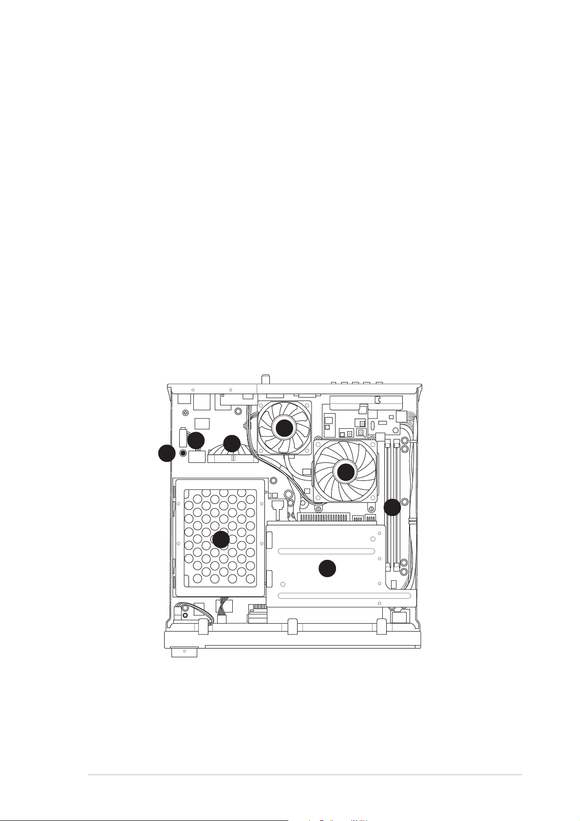
1.5 Internal components
The illustration below is the internal view of the system when you remove the
top cover. The installed components are labeled for your reference. Proceed
to Chapter 2 for instructions on installing other system components.
1. Standby power LED
2. HDD power plug
(to HDD power connector)
3. IDE cable
(to HDD connector)
13. VGA port. This port connects a VGA monitor.
14. DVI port. This port connects a DVI-enabled flat screen or LCD
monitor using a DVI cable.
15. HDTV/TV port. This port connects a high-definition television
(HDTV) or a regular TV set using the supplied HDTV, audio/video, or
video out cable.
16. USB 2.0 ports. These Universal Serial Bus 2.0 (USB 2.0) ports are
available for connecting USB 2.0 devices such as a mouse, printer,
scanner, camera, PDA, and others.
17. PS/2 keyboard port. This purple 6-pin connector is for a PS/2 keyboard.
4. Chassis fan
5. CPU fan
6. DIMM sockets
7. HDD metal tray
8. Optical drive shield
8
6
5
4
7
1
2
3
1-8
Chapter 1: System Introduction
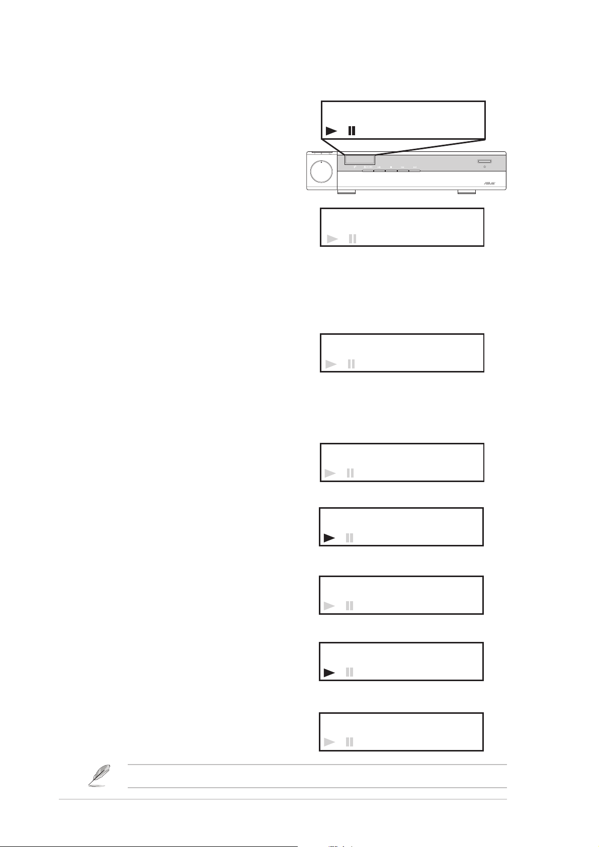
1.6 LED panel
The DiGiMatrix LED panel displays
different system information
depending on the system mode.
Time - The LED panel displays the
system time in 24-hour format when
DiGiMatrix is in soft-off or stand-by
mode, S3 (Suspend-to-RAM), or S4
(Suspend-to-Disk) state. Enter the
BIOS setup or the DiGiMatrix
operating system to adjust the time.
CPU Temperature - The LED panel
displays the CPU temperature in
degree Celsius when DiGiMatrix is in
Windows
®
mode.
00
18:30
— VOLUME +
00
00:00
10
88.70
.
HD CD
FM
HD CD
FM
HD CD
FM
Refer to page 3-21 on how to preset a radio station.
00
HD CD
FM
47:
0
C
Audio DJ
The LED panel displays the playlist
number when Audio DJ is set to HD
mode. In play status, the LED panel
displays the play icon, track number,
and track duration.
In DVD/CD mode, the LED panel
displays the audio mode. In play
status, the LED panel displays the
play icon, track number and track
duration.
The LED panel displays the station
preset number and station frequency
when Audio DJ is in radio mode.
P1
00:00
HD CD
FM
HD mode, standby/stopped status
01
02:45
HD CD
FM
HD mode, play/paused status
10:00CD
HD CD
FM
DVD/CD mode, standby/stopped status
01
01:29
HD CD
FM
DVD/CD mode, play/paused status
FM radio mode

ASUS DiGiMatrix
Chapter 2
Basic Installation
This chapter provides step-by-step
instructions on how to install components in
the ASUS DiGiMatrix system.
2-2
Chapter 2: Basic Installation
2.1 Preparation
Before you proceed, make sure that you have all the components that you
plan to install in the DiGiMatrix system.
Basic components to install
1. Hard disk drive (HDD)
2. Central processing unit (CPU)
3. DDR Dual Inline Memory Module (DIMM)
Tool
Phillips (cross) screw driver
2.2 Before you proceed
Take note of the following precautions before you install components into
the DiGiMatrix system.
1. Use a grounded wrist strap or touch a safely grounded object or to a
metal object, such as the power supply case, before handling
components to avoid damaging them due to static electricity.
2. Hold components by the edges to avoid touching the ICs on them.
3. Whenever you uninstall any component, place it on a grounded
antistatic pad or in the bag that came with the component.
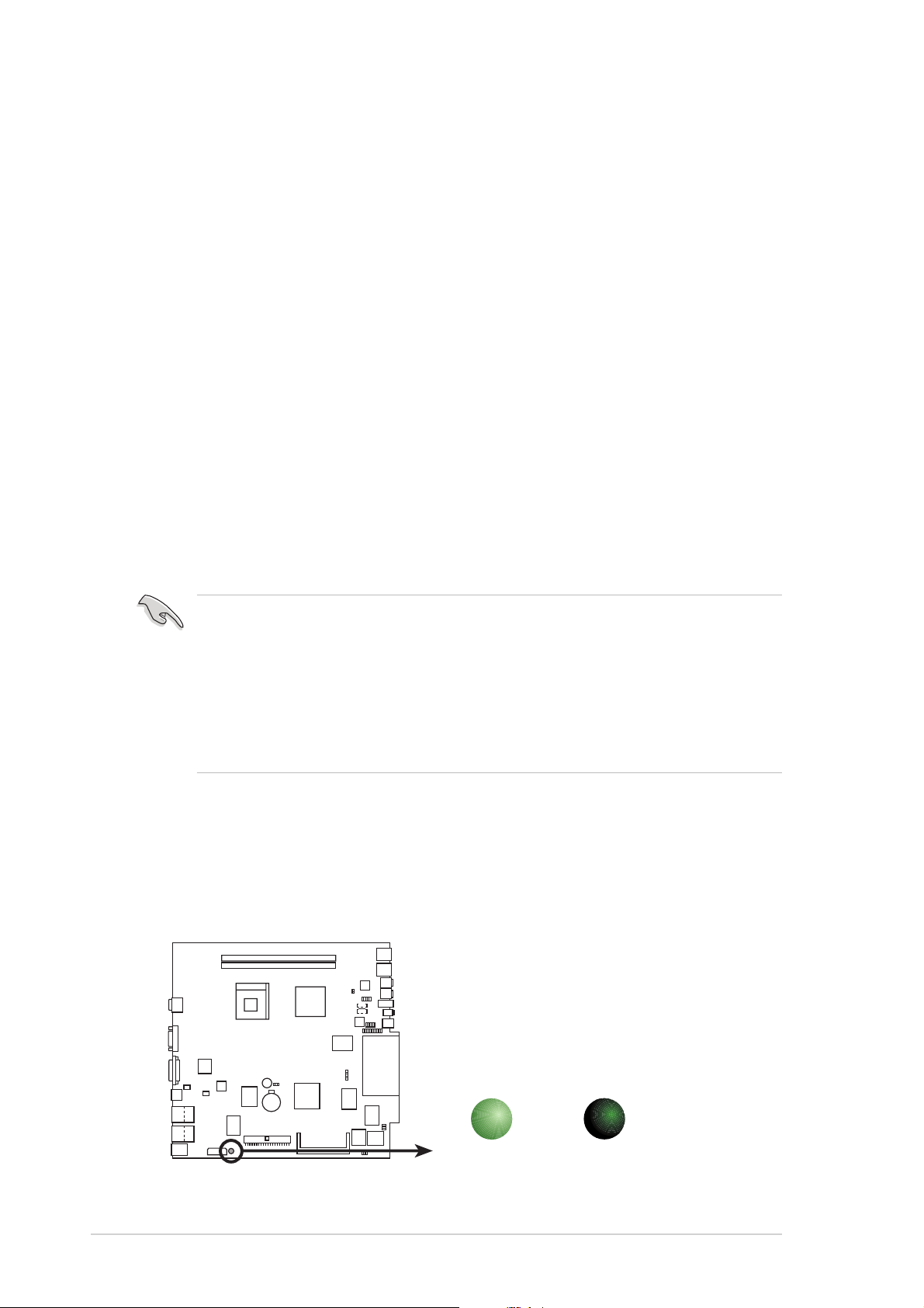
P4SQ
P4SQ Onboard LED
SBPWRLED
ON
Standby
Power
OFF
Powere
d
Off
The motherboard comes with an onboard standby power LED. When lit,
this LED indicates that the system is ON, in sleep mode or in soft-off
mode, and not powered OFF. Unplug the power cable from the power
outlet and make sure that the standby power LED is OFF before installing
any system component.
2-3
ASUS DiGiMatrix
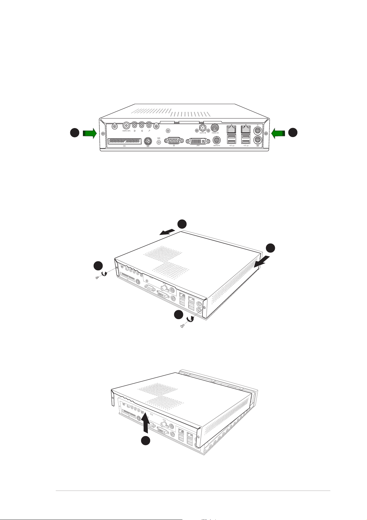
2.3 Removing the top cover
To remove the top cover:
1. On the rear panel, locate the two screws that secure the top cover to
the chassis.
2. Use a Phillips (cross) screw driver to remove the top cover screws.
Keep the screws for later use.
3. Pull the top cover slightly toward the rear panel until the side tabs are
disengaged from the chassis.
3
2
3
2
4. Hold the center edge of the top cover, then lift it up from the chassis.
Set the top cover aside.
4
1
1
2-4
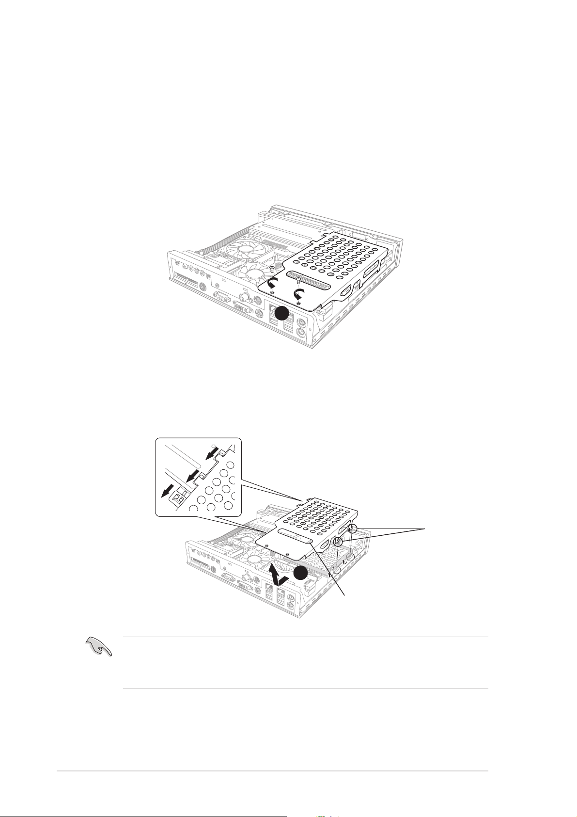
Chapter 2: Basic Installation
2. Use the hand slot to slide the metal cover toward the rear panel. Lift
the metal cover after the side hooks are disengaged from the HDD
tray rail and optical drive shield.
Set your hard disk drive as Master device before connecting the IDE cable
and power plug. Refer to the HDD documentation on how to set the drive
as a Master device.
2.4 Installing a hard disk drive
The DiGiMatrix system supports one UltraATA133 IDE hard disk drive
(HDD).
To install a hard disk drive:
1. Remove the two metal cover screws. Keep the screws for later use.
1
2
Hand slot
Side hooks
Side hooks
2-5
ASUS DiGiMatrix
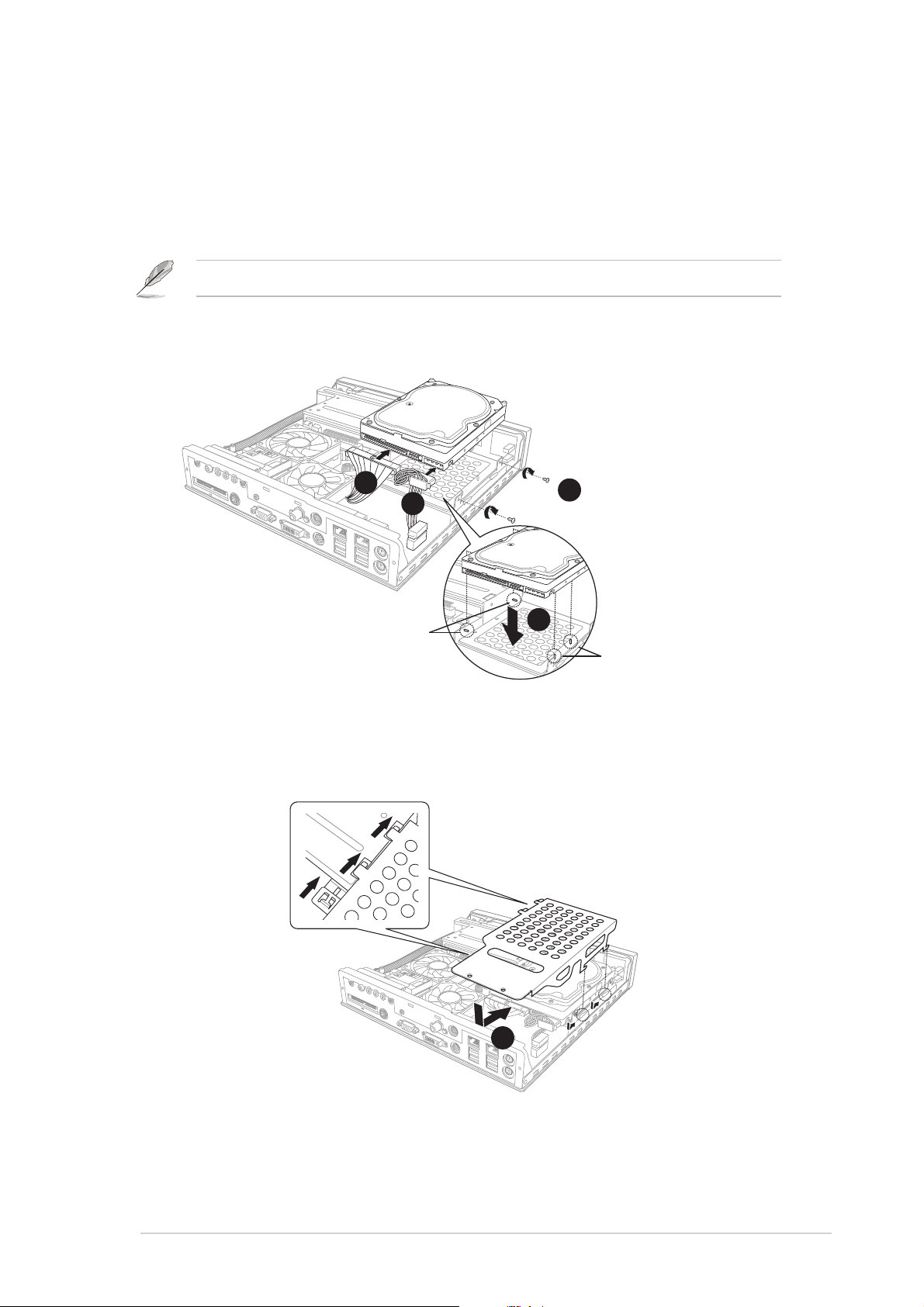
3. Connect the 40-pin IDE cable to the IDE connector on the drive.
4. Connect the 4-pin power plug to the HDD power connector.
5. Place the drive on the tray. Insert the tray metal tacks into the drive
screw holes (two at the side and two at the bottom).
6. Secure the drive with two side screws.
3
4
5
6
Metal tacks
(To side of the drive)
Metal tacks
(To bottom of the drive)
Insert the side metal tacks before inserting the bottom metal tacks.
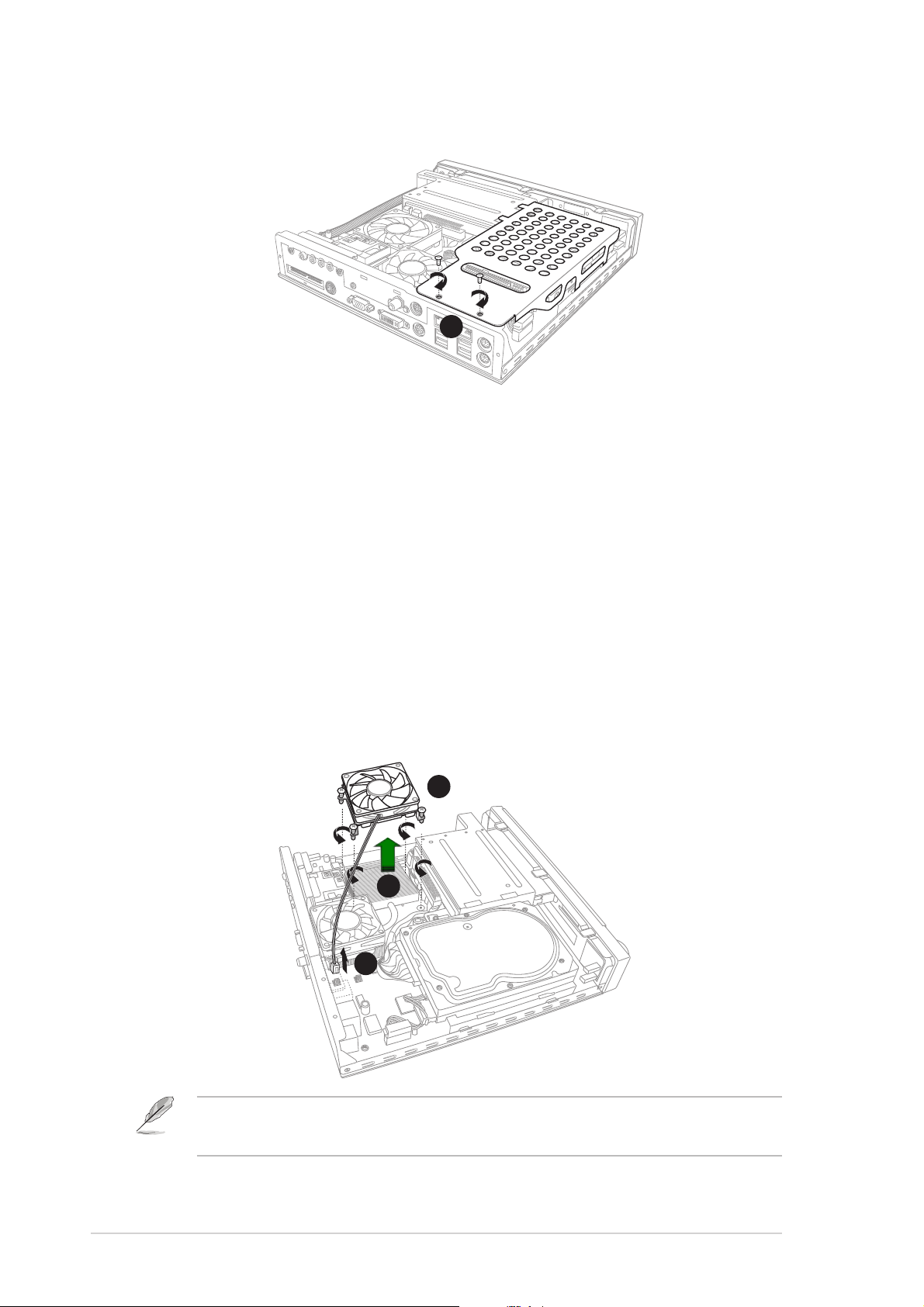
7. Replace the metal cover by aligning its side hooks with the tray rail
and optical drive shield. Slide the metal cover toward the front panel
until it fits in place.
7
2-6
Chapter 2: Basic Installation
2.5 Installing a CPU
The P4SQ motherboard comes with a surface mount 478-pin Zero
Insertion Force (ZIF) socket. This socket is specifically designed for
Intel
®
Pentium
®
4/Celeron processor.
To install a CPU:
1. Loosen the CPU fan screws.
2. Disconnect the CPU fan cable from the CPU fan connector on the
motherboard.
3. Lift the CPU fan.
3
1
2
8. Secure the metal cover with screws that you removed earlier.
8
The DiGiMatrix system comes with a pre-installed proprietary CPU fan. Do
not replace the CPU fan.
2-7
ASUS DiGiMatrix
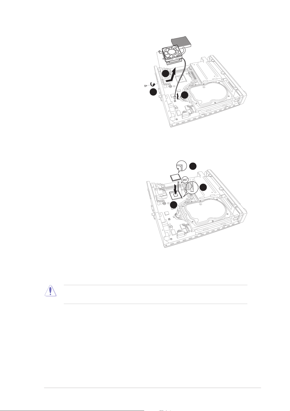
4. Remove the chassis fan and
heatsink assembly bracket
screw on the rear panel.
5. Disconnect the chassis fan
cable from the chassis fan
connector.
6. Move the chassis fan and
heatsink assembly slightly
toward the direction of the
front panel until it is
disengaged from the chassis.
Lift the chassis fan and
heatsink assembly.
7. Locate the 478-pin CPU socket
on the motherboard. Unlock the
socket by pressing the lever
sideways then lifting it up to a
90° angle.
8. Position the CPU above the
socket such that its marked
corner (gold mark) matches the
base of the socket lever.
9. Carefully insert the CPU to the
socket until it fits in place.
10. When the CPU is in place, push down the socket lever to secure the
CPU. The lever clicks on the side tab to indicate that it is locked.
7
9
8
The CPU fits only in one correct orientation. DO NOT force the CPU into
the socket to prevent bending the pins and damaging the CPU!
4
5
6
2-8
Chapter 2: Basic Installation
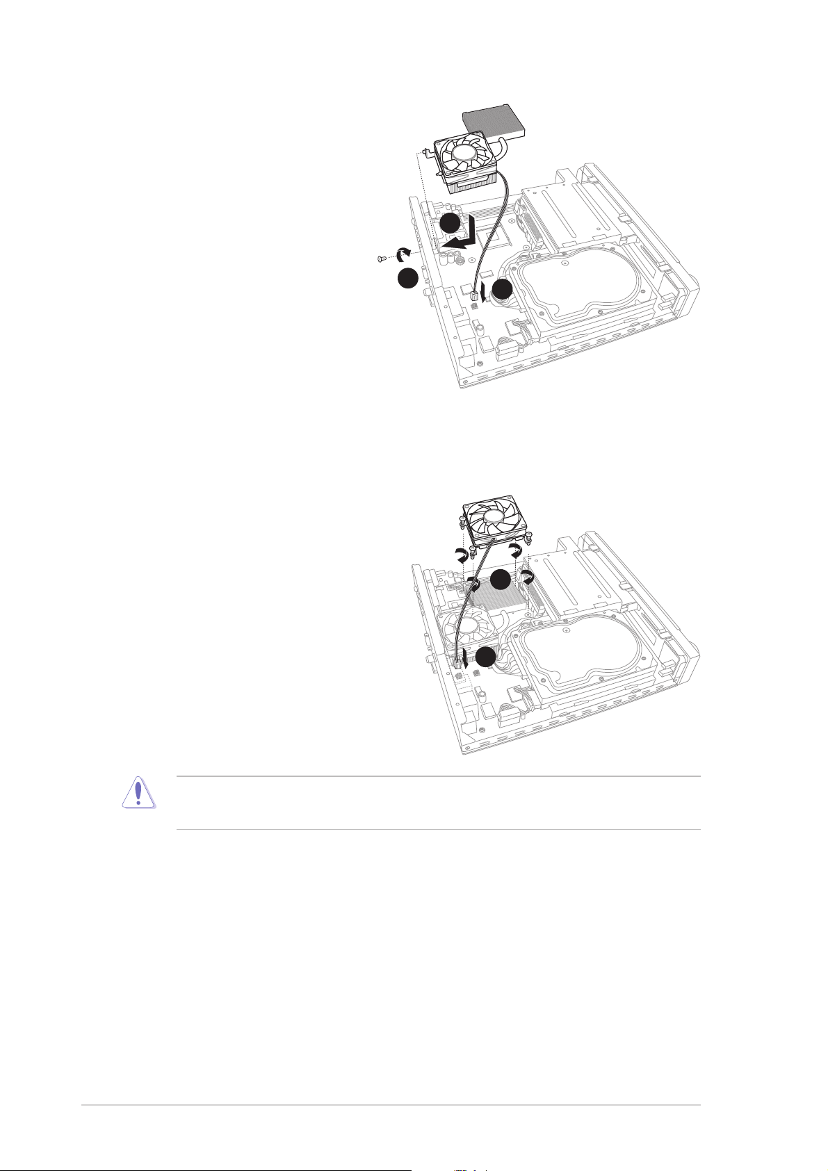
14. Reinstall the CPU fan over the
CPU heatsink. Fasten the
CPU fan screws to the
motherboard.
15. Connect the CPU fan cable to
the CPU fan connector. Refer
to page 4-11 for the location of
the CPU fan connector on the
P4SQ motherboard.
15
14
11. Reinstall the chassis fan
and heatsink assembly.
Align the bracket screw
hole with the rear panel
screw hole.
12. Secure the chassis fan
and heatsink assembly
with the screw you
removed earlier.
13. Connect the chassis fan
cable to the chassis fan
connector . Refer to page
4-11 for the location of the
chassis fan connector.
11
12
13
Do not overtighten the CPU fan screws! Doing so may damage the
motherboard.
2-9
ASUS DiGiMatrix
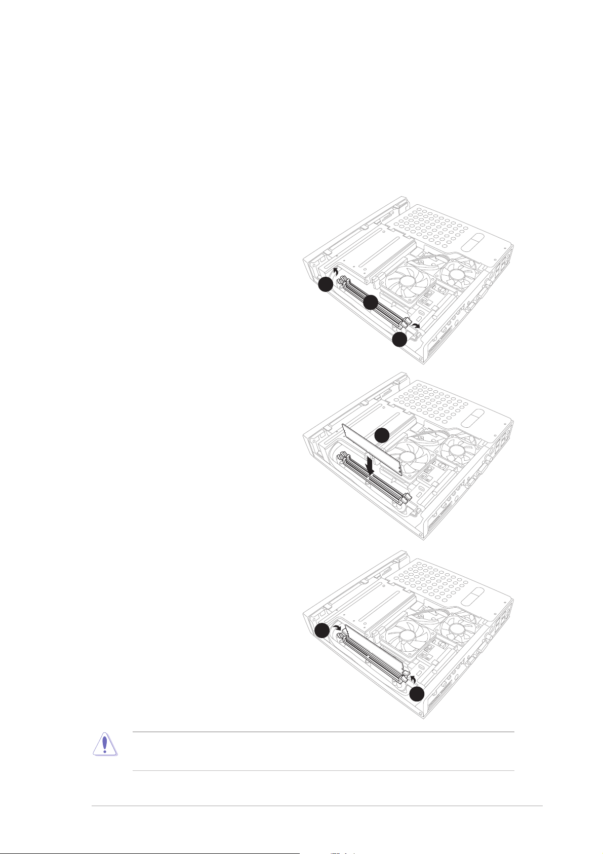
2.6 Installing a DIMM
The motherboard comes with two Double Data Rate (DDR) Dual Inline
Memory Module (DIMM) sockets. These sockets support up to 2GB
system memory using unbuffered non-ECC PC2700/2100/1600 DIMMs.
Follow these steps to install a DDR DIMM.
1. Locate the two DIMM sockets
on the motherboard.
2. Unlock a socket by pressing
the retaining clips outward.
4. Firmly insert the DIMM into the
socket until the retaining clips
snap back in place and the
DIMM is properly seated.
A DDR DIMM is keyed with a notch so that it fits in only one direction. DO
NOT force a DIMM into a socket to avoid damaging the DIMM.
3. Align a DIMM on the socket
such that the notch on the
DIMM matches the break on the
socket.
1
2
2
3
4
4
2-10
Chapter 2: Basic Installation
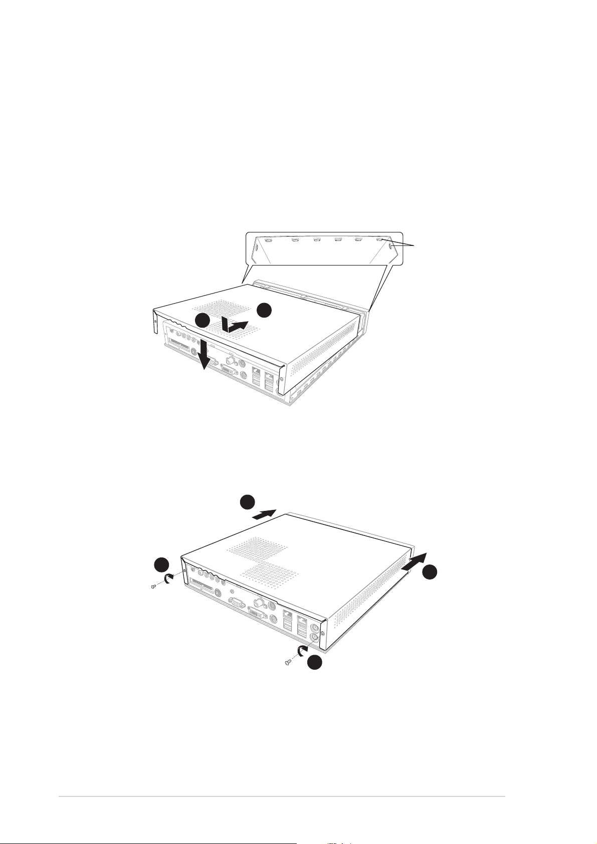
2.7 Replacing the top cover
After installing the components, follow these instructions to replace the top
cover.
1. Position the front edge of the top cover at least two inches from the
front panel cover. Fit the top cover tabs with the chassis rail and the
front panel cover tabs.
2. Lower the rear edge of the top cover as shown.
3. Push the top cover slightly toward the front panel until it fits in place.
4. Secure the top cover with two screws that you removed earlier.
3
4
3
4
1
Tabs
2
2-11
ASUS DiGiMatrix
2.8 Connecting cables
The DiGiMatrix package includes a universal power adapter (100V - 240V)
and various other cables to connect devices such as television, video
recorder, and audio system. The following sections describe how to
connect these cables.
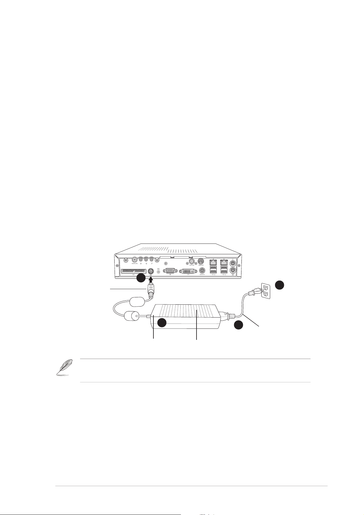
2.8.1 Power adapter and cable
The power adapter and cable lets you to use your DiGiMatrix anywhere
you are regardless of the power voltage in your area.
To connect the power adapter and power cable:
1. Connect the power cable (female plug) to the power adapter.
2. Connect the other end of the power cable (male plug) to a power outlet.
3. Check the power adapter LED. The LED lights up to indicate that the
power from the source is within the operating range.
4. Connect the DC IN power plug to the DiGiMatrix DC IN socket.
1
2
3
4
Power LED
Power cable
DC IN power
plug
Power adapter
Use an outlet adapter if the power plug does not fit the power outlet in your
area.
2-12
Chapter 2: Basic Installation
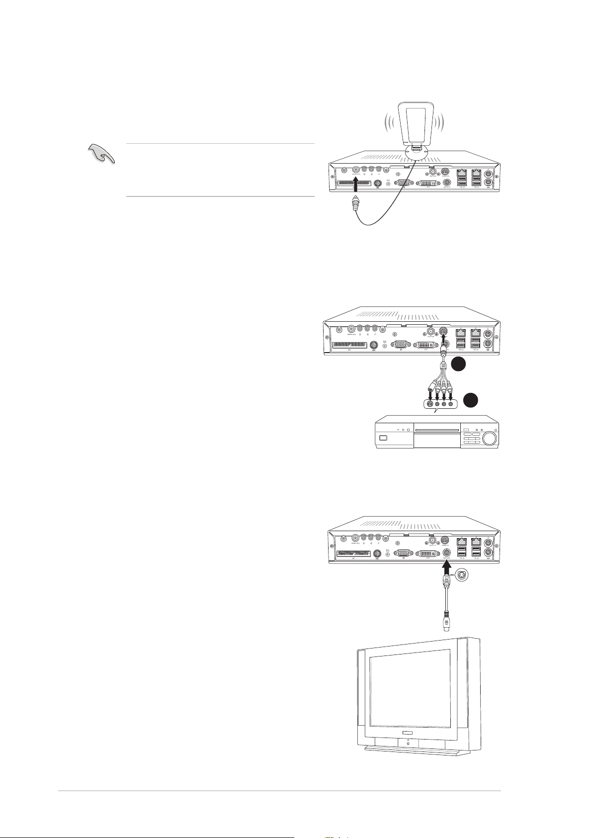
2.8.2 Radio antenna
Connect the radio antenna plug to the
DiGiMatrix antenna port.
2.8.3 Audio/Video cable
This cable connects a video casette recorder (VCR).
To connect the Audio/Video cable:
1. Connect the Audio/Video cable
plug to the S-Video port.
2. Connect the Audio/Video cable
S-Video output plug to the S-Video
port of your video casette recorder.
Connect the Audio/Video audio
output plugs to the audio input
ports of your video cassette
recorder.
2
1
2.8.4 Video out cable
The video out cable connects a television
set with an S-Video feature. Insert one
end of the video out cable to the HDTV
port. Connect the other end to the
S-Video port on your TV.
Place the radio antenna at an
elevated location to achieve better
reception.
Radio
antenna
VCR
TV with S-Video
 Loading...