

Page 1
K
Service Source
PowerBook 165c/180c
PowerBook 165c, PowerBook 180c
Page 2
K
Service Source
Basics
PowerBook 165c/180c
Page 3
Basics Overview - 1
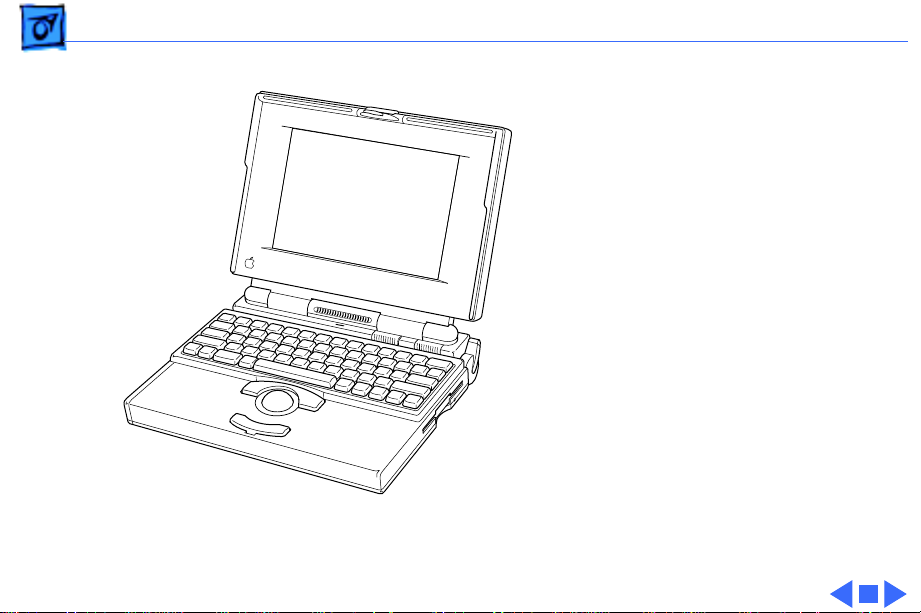
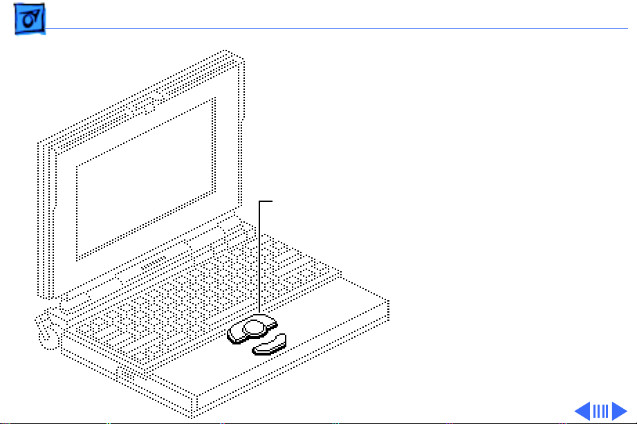
Overview
This manual includes
complete repair procedures
for the PowerBook 165C and
PowerBook 180C, shown at
left.
Figure: PowerBook 165C, 180C
Page 4

Basics Repair Strategy - 2
Repair Strategy
Service the PowerBook 165c and PowerBook180c through
module exchange and parts replacement. Customers can
request on-site service from an Apple Authorized Service
Provider Plus (AASP+) Apple Assurance (US only), or
request a courier through the Apple Canada Technical
Answerline (Canada only). They can also choose carry-in
service from an AASP.
Ordering
Apple Service Providers planning to support the computer
systems covered in this manual may purchase Service
modules and parts to develop servicing capability. To order
parts, use the AppleOrder (US only) or ARIS (Canada only)
system and refer to “Service Price Pages.”
Page 5

Basics Repair Strategy - 3
Large businesses, universities, and K-12 accounts must
provide a purchase order on all transactions, including
orders placed through the AppleOrder (US only) or ARIS
(Canada only) system.
USA Ordering
US Service Providers not enrolled in AppleOrder may fax
their orders to Service Provider Support (512-908-
8125) or mail them to
Apple Computer, Inc.
Service Provider Support
MS 212-SPS
Austin, TX 78714-9125
For US inquiries, please call Service Provider Support at
800-919-2775 and select option #1.
Page 6

Basics Repair Strategy - 4
Canadian Ordering
Canadian Service Providers not enrolled in ARIS may fax
their orders to Service Provider Support in Canada
(1-800-903-5284). For Canadian inquiries, please call
Service Provider Support at 905-513-5782 and select
option #3.
Page 7

Basics Warranty/AppleCare/ARIS - 5
Warranty/AppleCare/ARIS
US Only
The PowerBook 165c and PowerBook180c are covered
under the Apple One-Year Limited Warranty. The AppleCare
Service Plan is also available for these products. Service
Providers are reimbursed for warranty and AppleCare
repairs made to these computers. For pricing information,
refer to “Service Price Pages.”
Canada Only
The PowerBook 165c and PowerBook180c are covered
under first-year AppleCare. The Extended AppleCare
Service Plan is also available for these products. Service
Providers are reimbursed for first-year warranty and
Extended AppleCare repairs made to these computers. For
pricing information, refer to “Service Price Pages.”
Page 8
Basics Display Compatibility Matrix - 6
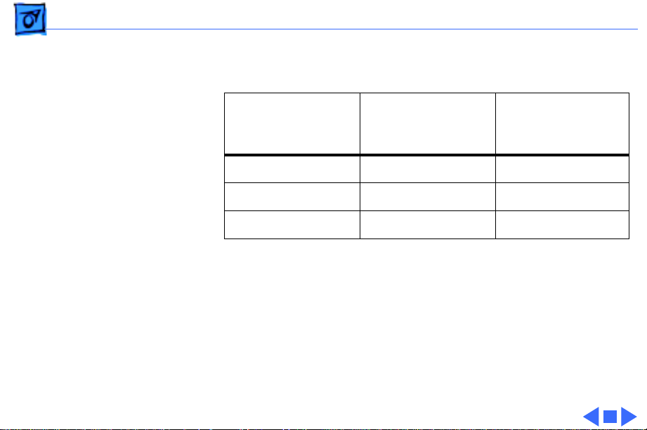
Display Compatibility Matrix
FSTN
PowerBook 165c
661-0752
Inverter 922-0374 922-0378
Display Cable 922-0373 922-0380
Inverter Cable 922-0566 922-0412
Important:
two displays—an active matrix and an FSTN display. Each of
these displays requires a compatible inverter and display
cable; the inverters, display cables, and displays are not
interchangeable. Before ordering one of these parts, refer to
the display matrix shown above.
The PowerBook 165c/180c family includes
Active Matrix
PowerBook 180c
661-0686
Page 9

K
Service Source
Specifications
PowerBook 165c/180c
Page 10

Specifications Introduction - 2
Introduction
Specifications information for this product can be found in this
chapter and also in the Spec Database, which you can access in one
of three ways:
• Launch it directly by double-clicking the Apple Spec Database
runtime alias at the top level of the Main Service Source CD.
• Select “Apple Spec Database” from the Service Source dropdown main menu.
• Click the Acrobat toolbar icon for the database, which is near
the right end of the toolbar with the letters “SP.”
Page 11

Specifications Configurations - 3
Configurations
Standard 165c
Standard 180c
Options
4 MB PSRAM, FSTN color display, 80/120 MB hard drive, 1.4
MB Apple SuperDrive, NiCad battery, AC adapter, and
microphone
4 MB PSRAM, 8.4 in (226 mm) diagonal backlit color active-
matrix LCD display, 80 or 160 MB hard drive, 1.4 MB Apple
SuperDrive, NiCad battery, AC adapter, and microphone
Internal PowerBook Express Modem (14,400 bps)
Internal PowerBook Fax/Data Modem (2400 bps)
4 MB memory expansion kit
PowerBook battery recharger
HDI-30 SCSI system cable
HDI-30 SCSI disk adapter
Page 12

Specifications Processor - 4
Processor
CPU
Coprocessor
Addressing
Motorola 68030 microprocessor
33 MHz
Motorola 68882 floating-point math coprocessor
33 MHz
32-bit internal registers
32-bit address bus
32-bit data bus
Page 13

Specifications Memory - 5
Memory
RAM
ROM
PRAM
4 MB pseudostatic RAM (PSRAM)
Expandable to 8 MB by adding 4 MB expansion card
Expandable to 14 MB with third-party PSRAM expansion cards
Requires 85 ns or faster RAM chips
1 MB
256 bytes of parameter memory
Page 14

Specifications Memory - 6
VRAM
Clock/Calendar
512K of video RAM supports internal display and external
monitor
CMOS custom chip with long-life lithium battery
Page 15

Specifications Disk Storage - 7
Disk Storage
Floppy Drive
Hard Drive
19 mm high, internal, 1.4 MB Apple SuperDrive
2.5 in. SCSI hard drives (many capacities)
Page 16

Specifications I/O Interfaces - 8
I/O Interfaces
Apple Desktop Bus
Serial
SCSI
Sound
ADB port (maximum of three ADB devices is recommended)
200 mA maximum current draw for all ADB devices
Two RS-422 serial ports; mini DIN-8 connectors
HDI-30 SCSI port with 1.5 MB/sec. transfer rate
Connect SCSI device to computer with HDI-30 SCSI system cable.
Monaural sound-in port; adapters required to input sound from
audio equipment with line level outputs (line level signals
must be attenuated 500:1)
Stereo sound-out jack for headphones or external audio amplifier
Page 17

Specifications I/O Interfaces - 9
Video
Power Adapter
Modem
Security
Video-out port; 8 bit, 256 color video support
Micro DB-15 connector
Supports most Macintosh monitors, VGA and SVGA monitors
Power adapter port
Slot for optional internal modem
Slot for third-party security equipment
Page 18

Specifications I/O Devices - 10
I/O Devices
Keyboard
Trackball
Microphone
Built-in keyboard with standard Macintosh layout
63 keys domestic; 64 keys ISO
3.0 mm travel; 18 mm vertical pitch, 18.63 mm horizontal pitch
Two-level tilt adjustment
30 mm diameter, dual button
Apple Desktop Bus (ADB) interface
Electret, omnidirectional
Output voltage of 4 mV, peak to peak
Page 19

Specifications Sound and Video - 11
Sound and Video
Sound Generator
PowerBook 165c
Video Display
PowerBook 180c
Video Display
Apple sound chip provides 4-voice, 8-bit sound
8-bit sound input, sampled at 11 or 22 kHz
9 in. (230 mm) diagonal screen
Flat-panel, color, film-compensated supertwist nematic (FSTN)
liquid crystal display
CCFL on-demand backlight
640 lines by 400 pixels; 8 bit; 256 colors
8.4 in. (215 mm) diagonal screen
Flat-panel, color, active-matrix, liquid crystal display
CCFL on-demand backlight
640 lines by 480 pixels; 8 bit; 256 colors
Page 20

Specifications Electrical - 12
Electrical
Main Battery
PRAM Battery
Power Adapter
Rechargeable nickel cadmium (NiCad) battery
Provides 1.5–2 hours of usage before recharging
3 V, 30 mAh rechargeable lithium battery
110–240 VAC line voltage
24 W, 50–60 Hz
US, United Kingdom, Australian, and European versions
Page 21

Specifications Physical - 13
Physical
PowerBook 165c
PowerBook 180c
Height: 2.29 in. (58 mm)
Width: 11.26 in. (286 mm)
Depth: 9.29 in. (236 mm)
Weight: 7.0 lb. (3.18 kg) with battery
Height: 2.34 in. (59 mm)
Width: 11.25 in. (286 mm)
Depth: 9.3 in. (236 mm)
Weight: 7.1 lb. (3.2 kg) with battery
Page 22

Specifications Environmental - 14
Environmental
Operating
Temperature
Storage
Temperature
Relative Humidity
Shipping Altitude
Operational Altitude
50–104° F (10–40° C)
-13 to 140° F (-25 to 60° C)
20–80% noncondensing
0–15,000 ft. (0–4722 m)
0–10,000 ft. (0–3048 m)
Page 23

Specifications Other - 15
Other
Fax/Data Modem
Internal 2400-baud modem with fax send at 9600 baud (includes
fax send software)
300/1200/2400 bps transmission rates
Serial binary and asynchronous protocols
Error correction and data compression: MNP 4, 5 and V.42,
V.42bis
Page 24

Specifications Other - 16
Express Modem
SCSI Disk Adapter
Internal 14,400-baud modem with fax send and receive
capability at 9600 baud
300 to 14,400 bps data transmission rates
2400/4800/7200/9600 bps fax transmission rates
Full duplex operation; asynchronous or framed modes
Error correction: V.42 compliance (MNP 2-4)
Data compression: V.42 bis (4 to 1 compression) and MNP-5 (2
to 1 compression)
Requires 300K of system RAM
Enables connection between PowerBook computer and desktop
Macintosh (PowerBook appears as a hard drive on the desktop)
Page 25

K
Service Source
Troubleshooting
PowerBook 165c/180c
Page 26

Troubleshooting General/ - 1
General
The Symptom Charts included in this chapter will help you
diagnose specific symptoms related to your product. Because cures
are listed on the charts in the order of most likely solution, try
the first cure first. Verify whether or not the product continues to
exhibit the symptom. If the symptom persists, try the next cure.
(Note: If you have replaced a module, reinstall the original module
before you proceed to the next cure.)
If you are not sure what the problem is, or if the Symptom Charts
do not resolve the problem, refer to the Flowchart for the product
family.
For additional assistance, contact Apple Technical Support.
Page 27

Troubleshooting Symptom Charts/Startup - 2
Symptom Charts
Startup
RAM failure occurs
(eight-tone error
chord sequence sounds
after startup chord)
Hardware failure
occurs (four-tone
error chord sequence
sounds after startup
chord)
1 Reseat PSRAM expansion card and check connection.
2 Replace PSRAM expansion card.
3 Replace daughterboard.
4 Replace motherboard.
1 Disconnect hard drive data cable and restart computer. If
startup sequence is normal, reconnect cable and retest.
2 Replace hard drive.
3 Disconnect floppy drive cable and restart computer. If
startup sequence is normal, reconnect cable and retest.
4 Replace floppy drive.
5 Replace motherboard.
Page 28

Troubleshooting Symptom Charts/Startup - 3
Startup
Screen displays
checkerboard pattern;
no startup chime
1 Reseat RAM expansion card.
2 Replace RAM expansion card.
3 Replace daughterboard.
4 Reseat display cable.
Page 29

Troubleshooting Symptom Charts/Power - 4
Power
Screen is blank;
computer doesn’t
respond
1 Restart computer.
2 Connect power adapter and restart computer in 3–4 minutes.
3 Try known-good, charged main battery.
4 Check all interconnect board, daughterboard, and
motherboard connections.
5 Reset the power manager.
6 Replace keyboard.
7 Replace interconnect board.
8 Replace daughterboard.
9 Replace motherboard.
10 PowerBook165c: Replace display.
11 PowerBook180c: Replace display (CPRC/international
repairers only).
Page 30

Troubleshooting Symptom Charts/Power - 5
Power
After you remove
main battery, some
Control Panel settings
are different
Power adapter is
plugged in, but
battery DA does not
indicate charger is
connected
1 Check cables.
2 Replace interconnect board.
3 Replace daughterboard.
4 Replace motherboard.
1 This is normal for fully charged battery.
2 Check battery charger connection.
3 Try known-good, charged main battery.
4 Try known-good power adapter.
5 Check battery thermistor cable connection.
6 Replace motherboard.
Page 31

Troubleshooting Symptom Charts/Power - 6
Power
Low-power warning
appears
Computer runs when
plugged into wall
outlet but not on
battery power;
battery voltage is
within tolerance
1 Recharge battery or attach power adapter.
2 Verify that peripherals are low-power.
3 PowerBook 165c: Remove external devices or connect power
adapter.
4 PowerBook 180c: Remove external devices.
5 Try known-good, charged main battery.
6 Try known-good power adapter.
7 Replace motherboard.
1 Reseat battery to make sure it is mating with contacts on
motherboard.
2 If motherboard includes removable fuse, replace fuse.
3 Replace motherboard.
4 Return computer to Apple.
Page 32

Troubleshooting Symptom Charts/Power - 7
Power
Computer won’t start
with battery removed
or with depleted
battery
The 180c powers on,
then powers off when
screen lights up
1 Make sure AC adapter is 24-watt.
2 Make sure battery is charged.
3 Replace AC adapter.
1 Make sure AC adapter is 24-watt. (“24W” should be
imprinted on the adapter. Or, check the model number, which
should be M5652). If it’s not a 24-watt adapter, replace it
Page 33

Troubleshooting Symptom Charts/Video - 8
Video
Row or partial row of
pixels never comes on
or is always on
PowerBook 165c:
1 Check cables.
2 Replace display cable.
3 Replace display.
4 Replace interconnect board.
PowerBook 180c:
5 Check cables.
6 Replace display cable.
7 Replace interconnect board.
8 Replace display (CPRC/international repairers only).
Page 34

Troubleshooting Symptom Charts/Video - 9
Video
Thin white line is
always on at middle of
screen
PowerBook 165c:
Thin white line is normal.
PowerBook 180c:
Replace display (CPRC/international repairers only) or return
computer to Apple.
Page 35

Troubleshooting Symptom Charts/Video - 10
Video
Display is very light
or totally white
1 PowerBook 165c: Adjust screen contrast.
2 Check display cable, converter, inverter, interconnect board,
daughterboard, and motherboard connections.
3 Replace converter board.
4 PowerBook 180c: Replace inverter board.
5 Replace interconnect board.
6 Replace display cable.
7 PowerBook 165c: Replace display.
8 PowerBook 180c: Replace display (CPRC/international
repairers only).
Page 36

Troubleshooting Symptom Charts/Video - 11
Video
No display, but
computer appears to
operate correctly
1 PowerBook 165c: Adjust screen contrast and backlight
intensity.
2 PowerBook 180c: Adjust backlight intensity.
3 Check display cable, converter, inverter, interconnect board,
daughterboard, and motherboard connections.
4 Connect power adapter.
5 Replace converter board.
6 PowerBook 180c: Replace inverter board.
7 Replace interconnect board.
8 Replace converter-to-inverter cable.
9 Replace display cable.
10 PowerBook 165c: Replace display.
11 PowerBook 180c: Replace display (CPRC/international
repairers only).
12 Replace daughterboard.
13 Replace motherboard.
Page 37

Troubleshooting Symptom Charts/Video - 12
Video
Rainbow colors
visible from extreme
viewing angles
Screen brightness is
not uniform
PowerBook 165c:
Such colors are normal for FSTN screens.
PowerBook 165c:
Irregularity in screen brightness is normal. Adjust contrast and
brightness to diminish effect.
PowerBook 180c:
Replace display (CPRC/international repairers only).
Page 38

Troubleshooting Symptom Charts/Video - 13
Video
Display stopped
working or dimmed
but is fine now
PowerBook 165c:
If temperature is in the approximate range of under 5 or over 40
degrees centigrade, this reaction is normal.
Page 39

Troubleshooting Symptom Charts/Video - 14
Video
Backlight doesn’t
operate
1 Verify that cables are not pinched or severed.
2 Check display cable, converter, inverter, interconnect board,
daughterboard, and motherboard connections.
3 Replace converter board.
4 PowerBook 180c: Replace inverter board.
5 Replace converter-to-inverter cable.
6 Replace interconnect board.
7 PowerBook 165c: Replace display.
8 Replace daughterboard.
9 Replace motherboard.
10 PowerBook 180c: Replace display (CPRC/international
repairers only).
Page 40

Troubleshooting Symptom Charts/Video - 15
Video
Screen goes blank 1 Press any key to wake computer from system sleep.
2 Check display cable connection.
3 Reseat daughterboard.
4 Replace daughterboard.
Page 41

Troubleshooting Symptom Charts/Video - 16
Video
Pixel is always white
or always black
PowerBook 180c: In general, no display should be replaced
because of subpixel irregularities. If the number of
irregularities on a display appears excessive, contact Apple for
more information.
Note: Each pixel on an active-matrix color display consists of
three subpixels (red, green, and blue). In turn, each subpixel
has a transistor that controls light transmission. A PowerBook
180c display, therefore, contains a total of 921,000 transistors
(640 x 480 x 3). Due to technology constraints, subpixel
transistor irregularities (red, green, blue, black, and white) are
allowed in this display.
PowerBook 165c: replace display.
Page 42

Troubleshooting Symptom Charts/Floppy Drive - 17
Floppy Drive
Audio and video
present, but internal
floppy drive does not
operate
Disk ejects while
booting; display
shows Macintosh icon
with blinking X
1 Try known-good floppy disk.
2 Check floppy drive cable connection.
3 Replace floppy drive cable.
4 Replace floppy drive.
5 Replace daughterboard.
6 Replace motherboard.
1 Try known-good system disk.
2 Verify that trackball or mouse button is not stuck.
3 Check floppy drive cable connection.
4 Replace floppy drive cable.
5 Replace floppy drive.
6 Replace motherboard.
Page 43

Troubleshooting Symptom Charts/Floppy Drive - 18
Floppy Drive
Disk does not eject 1 Switch off system and hold mouse button down while you
switch system on.
2 Insert opened paper clip into hole beside drive.
3 Check floppy drive cable connection.
4 Replace floppy drive cable.
5 Replace floppy drive.
6 Replace daughterboard.
7 Replace motherboard.
Disk initialization
fails
1 Try known-good floppy disk.
2 Install inverter shield (if absent).
3 Check floppy drive cable connection.
4 Replace floppy drive cable.
5 Replace floppy drive.
Page 44

Troubleshooting Symptom Charts/Floppy Drive - 19
Floppy Drive
Read/write/copy
error
1 Try known-good floppy disk.
2 Install inverter shield if absent.
3 Check floppy drive cable connection.
4 Replace floppy drive cable.
5 Replace floppy drive.
Page 45

Troubleshooting Symptom Charts/Hard Drive - 20
Hard Drive
Internal hard drive
does not operate
1 Disconnect external SCSI devices.
2 Check internal hard drive cable connection.
3 Use HD SC Setup to reinitialize drive.
4 Replace internal hard drive cable.
5 Replace internal hard drive.
6 Replace motherboard.
Page 46

Troubleshooting Symptom Charts/Peripheral - 21
Peripheral
After you connect
external SCSI device,
computer does not
boot
1 Switch on external SCSI device before starting computer.
2 Check cable connections.
3 Verify that standard Apple terminator terminates SCSI chain
at beginning and end.
4 Verify that SCSI select switch setting on external device is
unique.
5 Verify operation of internal hard drive.
6 Try known-good external SCSI device.
7 Replace motherboard.
Page 47

Troubleshooting Symptom Charts/Peripheral - 22
Peripheral
Cursor does not move
when you are using
trackball
Cursor intermittently
does not move or
moves erratically
1 Restart computer.
2 Check cables.
3 Check interconnect board, daughterboard, and motherboard
connections.
4 Try low-power mouse. If cursor moves, replace trackball or
keyboard.
5 Replace interconnect board.
6 Replace daughterboard.
7 Replace motherboard.
1 Restart computer.
2 Check cables.
3 Replace trackball.
4 Replace keyboard.
5 Replace interconnect board.
6 Replace motherboard.
Page 48

Troubleshooting Symptom Charts/Peripheral - 23
Peripheral
Cursor moves, but
clicking trackball
button has no effect
Cursor does not move
when you are using
mouse
1 Restart computer.
2 Check interconnect board, daughterboard, and motherboard
connections.
3 Replace trackball.
4 Replace keyboard.
5 Replace interconnect board.
6 Replace daughterboard.
7 Replace motherboard.
1 Check mouse connection to ADB port.
2 Restart computer.
3 Clean mouse ball and inside mouse.
4 Replace mouse.
5 Replace motherboard.
Page 49

Troubleshooting Symptom Charts/Peripheral - 24
Peripheral
No response to any
key on keyboard
Known-good directconnect printer does
not print
1 Reset power manager. (Unplug power adapter, shut down
computer, wait, and then restart computer.)
2 Check connections of keyboard to interconnect board, and
interconnect board to daughterboard.
3 Replace keyboard.
4 Replace interconnect board.
5 Replace daughterboard.
1 Verify that System is 7.1 or later.
2 Verify that Chooser and Control Panel settings are correct.
3 Check cables.
4 Replace printer interface cable.
5 Try known-good printer.
6 Replace daughterboard.
7 Replace motherboard.
Page 50

Troubleshooting Symptom Charts/Peripheral - 25
Peripheral
Known-good network
printer does not print
Device connected to
external modem port
doesn’t work
1 Verify that System is 7.1 or later.
2 Verify that Chooser and Control Panel settings are correct.
3 Check cables.
4 Replace printer interface cable.
5 Try known-good printer. If printer works, troubleshoot
network.
6 Replace daughterboard.
7 Replace motherboard.
1 Verify that External Modem is selected in CDEV.
2 Verify that System is 7.1 or later.
3 Check cables.
4 Test device with known-good computer.
5 Replace daughterboard.
6 Replace motherboard.
Page 51

Troubleshooting Symptom Charts/Peripheral - 26
Peripheral
I/O devices are
unrecognized or
garbage is
transmitted or
received
1 Verify that System is 7.1 or later.
2 Check cables.
3 Verify that SCSI device has standard Apple terminator.
4 Verify that SCSI select switch setting on external device is
unique.
5 Test device with known-good computer.
6 Replace daughterboard.
7 Replace motherboard.
Page 52

Troubleshooting Symptom Charts/Internal Modem - 27
Internal Modem
Internal modem
options do not appear
in CDEV
Modem does not
respond properly to
AT command set
instructions
1 Remove and reseat modem card.
2 Verify that System is 7.1 or later.
3 Replace modem card.
4 Replace motherboard.
1 Verify that baud rate and data format settings of
communications application are compatible with internal
modem and remote modem.
2 Check phone cord connection and operation.
3 Remove and reseat modem card.
4 Verify that System is 7.1 or later.
5 Replace modem card.
Page 53

Troubleshooting Symptom Charts/Internal Modem - 28
Internal Modem
Strange mix of
characters appears on
screen
Modem interferes
with system sound
1 Verify that baud rate and data format settings of
communications application are compatible with internal
modem and remote modem.
2 Check phone cord connection and operation.
3 Remove and reseat modem card.
4 Verify that System is 7.1 or later.
5 Replace modem card.
6 Replace daughterboard.
7 Replace motherboard.
1 Remove and reseat modem card.
2 Replace modem board.
3 Replace interconnect card.
4 Replace motherboard.
Page 54

Troubleshooting Symptom Charts/Internal Modem - 29
Internal Modem
Modem does not
respond to incoming
call
Modem has no sound
output
Modem connects but
does not communicate
with remote modem
1 If computer is in sleep mode, verify that Wake On Ring option
in CDEV is selected.
2 Check phone cord connection and operation.
3 Replace modem card.
4 Replace motherboard.
1 Verify that Control Panel volume setting is above 0.
2 Replace modem card.
3 Replace interconnect card.
4 Replace motherboard.
1 Verify that remote modem needs error correction (error
correction is internal modem default).
2 Type AT &Q0 to disable error correction.
Page 55

Troubleshooting Symptom Charts/Miscellaneous - 30
Miscellaneous
Screen goes blank and
computer shuts down
every few minutes
Application seems to
run slower after few
seconds
Hard drive is slow to
respond, or screen
goes blank too often
Adjust sleep delays in Control Panel or connect power adapter.
1 Disable System Rest. (See owner’s manual.)
2 Connect power adapter.
Adjust sleep delays in Control Panel or connect power adapter.
Page 56

Troubleshooting Symptom Charts/Miscellaneous - 31
Miscellaneous
No sound from
speaker
1 Verify that volume setting in Control Panel is above 0.
2 Verify that no external speaker is plugged in.
3 Check connections of speaker to interconnect board,
interconnect board to daughterboard, and daughterboard to
motherboard.
4 Replace interconnect board.
5 Replace daughterboard.
6 Replace motherboard.
Page 57

Troubleshooting PowerBook 165c/180c Startup Problems Flowchart/
PowerBook 165c/180c Startup Problems
Flowchart
START
Reset the power
manager.
Press the power button to
begin the startup sequence.
Do the
startup tones
sound?
Yes
Is the
startup tone
normal?
Yes
Does a
gray pattern
appear?
Yes
1
No
No
No
Does any
video
appear?
Yes
1. Check the cables.
2. Replace the interconnect board.
3. Replace the daughterboard.
4. Replace the motherboard.
See Startup Problems in
the Symptom/Cure Chart.
1. Check the cables.
2. Replace the inverter board.
3. Replace the interconnect board.
4. Replace the display cable.
PowerBook 520, 520c, 540,
540c: Replace the interconnect to-display cable.
5. Replace the display.
PowerBook 170, 180, 180c:
Replace the display
(international only) or
return the computer to Apple.
6. Replace the daughterboard.
7. Replace the motherboard.
No
1. Replace the daughterboard.
2. Replace the motherboard.
Page 58

Troubleshooting PowerBook 165c/180c Startup Problems Flowchart/
PowerBook 165c/180c Startup Problems Flowchart
(continued)
1
Does
the desktop
appear?
Yes
Do the
trackball and
keyboard
function?
Yes
Does
No
No
the disk icon with
the flashing question
mark remain on the
screen?
Yes
1. Reset parameter RAM.
2. Use HD SC Setup to update the SCSI driver.
3. Reinstall System Software.
4. Replace the internal hard drive cable.
5. Replace the hard drive.
6. Replace the motherboard.
7. Replace the daughterboard.
1. Reset the power manager.
2. Check the cables.
3. Replace the trackball (or track pad).
4. Replace the keyboard.
5. Replace the interconnect board.
6. Replace the daughterboard.
7. Replace the motherboard.
1. Replace the
No
daughterboard.
2. Replace the
motherboard.
Go to
Start
Insert a known-good disk
into the floppy disk drive
and try to initialize it.
Does the
disk
initialize?
Yes
END
No
1. Replace the floppy drive cable.
2. Replace the floppy drive.
Page 59

K
Service Source
Take Apart
PowerBook 165c/180c
Page 60

Take Apart Main Battery - 1
Main Battery
Before you begin,
disconnect the power
adapter.
Note:
This procedure also
covers removal of the main
battery door.
Main Battery
Important:
the main battery, use the
Macintosh Shut Down
command.
Before removing
Page 61

Take Apart Main Battery - 2
±
Warning:
battery contains toxic
materials. Review battery
handling and disposal
instructions in Bulletins/
Safety.
1 Slide open the battery
door.
2 Using the battery door as
a handle, pull out the
main battery.
The main
Page 62

Take Apart Main Battery - 3
3 Slide the battery door
completely open.
4 Pull the end tab until it
releases, and remove
the door from the
battery.
End Tab
Page 63

Take Apart I/O Door - 4
I/O Door
No preliminary steps are
required before you begin
this procedure.
I/O Door
Caution:
165c/180c contains CMOS
devices that are very
susceptible to ESD damage.
Review the ESD precautions
in Bulletins/Safety.
The PowerBook
Page 64

Take Apart I/O Door - 5
1 Open the I/O door.
2 Carefully bend the door
so that the middle bows
Peg
downward and unhinge
the two pegs located at
the bottom corners.
Page 65

Take Apart Top Case - 6
Top Case
Before you begin, remove
the following:
• Main battery
• I/O door
Top Case
Caution:
165c/180c contains CMOS
devices that are very
susceptible to ESD damage.
Review the ESD precautions
in Bulletins/Safety.
The PowerBook
Page 66

Take Apart Top Case - 7
1
Note:
Use a T-8 Torx
driver to remove the
small screw from the
rear connector panel
and a T-10 Torx driver
to remove the other case
screws.
Remove the five Torx
screws from the bottom
case.
Page 67

Take Apart Top Case - 8
2 Lift the back of the top
case and disconnect the
interconnect cable.
3 Lift off the top case and
unhook the two tab
Interconnect
Cable
fasteners from the front
of the bottom case.
Tab Fastener
Replacement Caution:
When
connecting the interconnect
cable connector, fold the
cable as shown. If it is not
folded correctly, the cable
could short.
Page 68
Take Apart Trackball Assembly - 9
Trackball Assembly
Before you begin, remove
the following:
• Main battery
• I/O door
Trackball
Assembly
• Top case
Caution:
165c/180c contains CMOS
devices that are very
susceptible to ESD damage.
Review the ESD precautions
in Bulletins/Safety.
The PowerBook
Page 69

Take Apart Trackball Assembly - 10
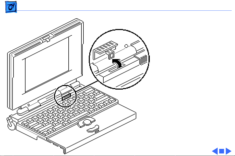
1
Trackball
Ribbon Cable
Locking
Tab
Caution:
ribbon cable is fragile
and should be handled
with care.
The trackball
Pull out the locking tab
on the trackball
connector and disconnect
the trackball ribbon
cable.
Page 70

Take Apart Trackball Assembly - 11
2 Using a T-8 Torx
driver, remove the two
mounting screws and
lift the trackball
assembly from the top
case.
Page 71

Take Apart Keyboard - 12
Keyboard
Before you begin, remove
the following:
• Main battery
• I/O door
Keyboard
• Top case
• Trackball assembly
Caution:
165c/180c contains CMOS
devices that are very
susceptible to ESD damage.
Review the ESD precautions
in Bulletins/Safety.
The PowerBook
Page 72

Take Apart Keyboard - 13
1
Caution:
The keyboard
ribbon cables are fragile
and should be handled
with care.
Lift the locking tabs on
Keyboard
Ribbon Cables
the two keyboard
connectors and
disconnect the keyboard
ribbon cables.
Page 73

Take Apart Keyboard - 14
2 Using a T-8 Torx
driver, remove the
seven mounting screws
and lift the keyboard
from the top case.
Page 74

Take Apart DC/DC Converter - 15
DC/DC Converter
Before you begin, remove
the following:
• Main battery
• I/O door
• Top case
DC/DC Converter
Caution:
165c/180c contains CMOS
devices that are very
susceptible to ESD damage.
Review the ESD precautions
in Bulletins/Safety.
The PowerBook
Page 75

Take Apart DC/DC Converter - 16
1 Remove the two
mounting screws.
2
Note:
Do not remove the
Shield
shield from the DC/DC
converter.
Converter-toInverter Cable
DC/DC
Converter
Pull the DC/DC
converter and attached
shield straight up and off
the connector on the
interconnect board.
3 Disconnect the
converter-to-inverter
cable.
Page 76

Take Apart DC/DC Converter - 17
Brightness Pot
Actuator Actuator
Contrast Pot
DC/DC
Converter
PowerBook 165c
Replacement Note:
to align the brightness and
contrast pots on the DC/DC
converter with the plastic
actuators on the top case. It
is easiest to align the pots
and actuators if you set both
to their extreme outer
positions.
Be sure
Page 77

Take Apart DC/DC Converter - 18
Brightness Pot
Actuator
DC/DC
Converter
PowerBook 180c
Replacement Note:
to align the brightness pot
on the DC/DC converter with
the plastic actuator on the
top case. It is easiest to align
the pot and actuator if you
set both to their extreme
outer positions.
Be sure
Page 78

Take Apart DC/DC Converter - 19
Shield
DC/DC
Converter
Replacement Note:
If you
are replacing the DC/DC
converter, order both the
converter and its shield
(part number 922-0418).
Install the new shield on the
converter before replacing
it. Do not reuse the original
shield.
Page 79

Take Apart Interconnect Board - 20
Interconnect Board
Before you begin, remove
the following:
• Main battery
• I/O door
• Top case
• DC/DC converter
Interconnect Board
Caution:
165c/180c contains CMOS
devices that are very
susceptible to ESD damage.
Review the ESD precautions
in Bulletins/Safety.
The PowerBook
Page 80

Take Apart Interconnect Board - 21
±
J3 Connector
J5 Connector
Warning:
interconnect board contains
hazardous materials.
Return bad interconnect
boards to Apple for proper
disposal.
1
Caution:
and display cables are
fragile and should be
handled with care.
Lift the locking tabs on
connectors J5 and J3 and
disconnect the keyboard
ribbon cables.
The
The keyboard
Page 81

Take Apart Interconnect Board - 22
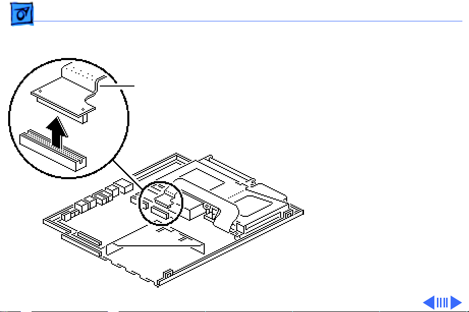
2
Note:
The display cable
will not come entirely
out of the connector until
you remove the
interconnect board from
the top case.
Pull out the locking tab
on connector J2 and ease
the display cable out of
the connector as far as
the cable will go.
J2 Connector
Replacement Note:
Connect
the display cable before
replacing the interconnect
board.
Page 82

Take Apart Interconnect Board - 23
3 Using a T-8 Torx
driver, remove the two
mounting screws and
lift the interconnect
board from the top case.
Page 83

Take Apart Actuators - 24
Actuators
Before you begin, remove
the following:
• Main battery
• I/O door
• Top case
• DC/DC converter
Actuators
Caution:
165c/180c contains CMOS
devices that are very
susceptible to ESD damage.
Review the ESD precautions
in Bulletins/Safety.
The PowerBook
Page 84
Take Apart Actuators - 25
Replacement Note:
PowerBook 180c has only
one brightness actuator.
1 Pull up the contrast
actuator, rotate it
toward the display, and
remove the actuator
from the top case.
2 Repeat for the
brightness actuator.
The
Page 85

Take Apart Elevation Foot - 26
Elevation Foot
Before you begin, remove
the following:
• Main battery
• I/O door
• Top case
Elevation
Foot
Elevation Foot
Caution:
165c/180c contains CMOS
devices that are very
susceptible to ESD damage.
Review the ESD precautions
in Bulletins/Safety.
The PowerBook
Page 86

Take Apart Elevation Foot - 27
1 Using a T-8 Torx
driver, remove the Torx
screw, washer, and
spring clip from the
inside of the elevation
foot.
2 Pull off the elevation
Spring
Clip
Elevation
Foot
foot.
Page 87

Take Apart Cousin Card - 28
Cousin Card
Before you begin, remove
the following:
• Main battery
• I/O door
• Top case
• PSRAM expansion card
(if present)
Cousin Card
Caution:
165c/180c contains CMOS
devices that are very
susceptible to ESD damage.
Review the ESD precautions
in Bulletins/Safety.
The PowerBook
Page 88

Take Apart Cousin Card - 29
Cousin Card
Daughterboard
Logic Board
Take-Apart
Tool
Caution:
Always use the
logic board take-apart tool
to separate the cousin card
connector from the
daughterboard connector.
Trying to disconnect the
cousin card from the
daughterboard by rocking
or peeling the boards apart
damages the connectors.
Using the Apple logic board
take-apart tool, disconnect
the cousin card from the
daughterboard.
Page 89

Take Apart Daughterboard - 30
Daughterboard
Before you begin, remove
the following:
• Main battery
• I/O door
• Top case
• PSRAM expansion card
(if present)
• Cousin card
Daughterboard
Caution:
165c/180c contains CMOS
devices that are very
susceptible to ESD damage.
Review the ESD precautions
in Bulletins/Safety.
The PowerBook
Page 90

Take Apart Daughterboard - 31
Logic Board
Take-Apart
Tool
Daughterboard
Motherboard
1 Using a T-8 Torx
driver, remove the four
daughterboard mounting
screws.
2
Caution:
Always use the
logic board take-apart
tool to separate the
daughterboard
connector from the
motherboard connector.
Trying to disconnect the
daughterboard from the
motherboard by rocking
or peeling the boards
apart damages the
connectors.
Page 91

Take Apart Daughterboard - 32
Using the Apple logic
board take-apart tool,
disconnect the
daughterboard from the
Heat Sinks
motherboard.
Daughterboard
Replacement Note:
The
green heat sinks attached to
the daughterboard are made
of delicate heat-conducting
material. If they are missing
or damaged, they must be
replaced.
Replacement Note:
To
replace a damaged heat sink,
carefully peel it from the
daughterboard. Select the
Page 92

Take Apart Daughterboard - 33
appropriately sized heat
sink from the heat sink kit
(part number 076-0069),
and gently press the part
into place.
Replacement Caution:
sure the heat sink is placed
exactly as shown in the
illustration. The heat sink
should not hang over the side
of the component it is
covering, or it may short
the component leads.
Make
Page 93

Take Apart Motherboard - 34
Motherboard
Before you begin, remove
the following:
• Main battery
• I/O door
• Top case
• PSRAM expansion card
(if present)
• Cousin card
• Daughterboard
• Modem card (if present)
Motherboard
Caution:
165c/180c contains CMOS
devices that are very
susceptible to ESD damage.
The PowerBook
Page 94

Take Apart Motherboard - 35
Floppy Drive Cable
Thermistor Cable
Locking Tab
Locking
Tab
Hard Drive
Cable
Review the ESD precautions
in Bulletins/Safety.
Caution:
The hard drive,
floppy drive, and thermistor
cables are fragile and
should be handled with care.
1 Lift the locking tabs and
disconnect the floppy
drive and thermistor
cables.
2 Remove the hard drive
cable.
Page 95

Take Apart Motherboard - 36
Hex-Head Screw
Motherboard
3 Remove the two hex-
head screws and lift the
motherboard from the
bottom case.
Page 96

Take Apart Motherboard - 37
Replacement Note: To
replace the insulator on the
sound jack assembly,
carefully peel off the
original insulator. Remove
Sound Jack Insulator
the paper backing on the
replacement insulator, and
Sound Jack
Assembly
gently press it into place.
Replacement Caution: Make
sure the replacement
insulator sits in exactly the
same position as the original
insulator.
Motherboard
Page 97

Take Apart Hard Drive - 38
Hard Drive
Before you begin, remove
the following:
• Main battery
• I/O door
• Top case
• Modem card (if present)
• PSRAM expansion card
(if present)
• Cousin card
• Daughterboard
Caution: The PowerBook
165c/180c contains CMOS
devices that are very
susceptible to ESD damage.
Hard Drive
Page 98
Take Apart Hard Drive - 39
Review the ESD precautions
in Bulletins/Safety.
Hard Drive
Cable
1 Caution: The hard drive
cable is fragile and
should be handled with
care.
Disconnect the hard
drive cable from the
motherboard.
Page 99

Take Apart Hard Drive - 40
2 Using a T-8 Torx
driver, remove the five
Retainer
Latch
screws from the drive
retainer.
3 Using a jeweler’s
screwdriver, release the
drive retainer latch and
remove the retainer.
Drive Retainer
Page 100

Take Apart Hard Drive - 41
4 Lift the hard drive from
the case.
5 Pull the release loop and
disconnect the hard drive
cable.
Note: If the cable does
not have a release loop,
Release Loop
gently pry the cable
from the drive with a
screwdriver.
Replacement Note: For
information on returning
drives, cables, and carriers
to Apple, refer to the Hard
Drives manual.
 Loading...