

Page 1
K
Service Source
iMac, iMac DV, iMac DV+,
iMac DV Special Edition
Updated 11 July 2005
© 2001 Apple Computer, Inc. All rights reserved.
Page 2

K
Service Source
Basics
iMac, Mac DV, iMac DV+, iMac
DV Special Edition
Page 3
Basics Overview - 1
Overview
Product Description
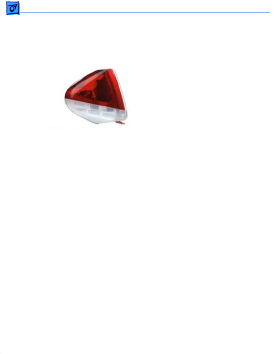
The new iMac models are
available in four models:
iMac, iMac DV, iMac DV+,
and the iMac DV Special
Edition. And, there five new
colors: indigo, ruby, sage,
graphite, and snow. The new
iMacs offer several new,
unique features, including
increased processor speed
and hard disk storage, a new
keyboard an optical sensor
mouse.
Page 4

Basics New Features - 2
New Features
Processor Speed
There are four shipping configurations: 350, 400, 450, and
500 MHz, designed around the PowerPC G3 microprocessor.
• 350 MHZ (iMac)
• 400 MHz (iMac DV)
• 450 MHz (iMac DV+)
• 500 MHz (iMac DV Special Edition)
Page 5

Basics New Features - 3
Memory
• 64 MB SDRAM
• 128 MB SDRAM of PC-100 SDRAM (168-pin, running
at 125 MHz (8 ns) or faster
The RAM slots can support up to 512 MB each for a
maximum total of 1 GB.
Hard Disk Storage
• 7 GB EIDE
• 10 GB EIDE
• 20 GB EIDE
• 30 GB EIDE
Page 6

Basics New Features - 4
CD-ROM or DVD-ROM Drive
• 24x-speed, slot-load, ATAPI CD-ROM drive
• 6x-speed, slot-load, ATAPI DVD-ROM drive
Graphics Support
• The graphics controller IC is an ATI RAGE 128 Pro
Keyboard
• The computer comes with a new full-size keyboard with
15 function keys and separate groups of numeric keypad
and editing keys.
There is no power key on this keyboard.
Note:
Page 7

Basics New Features - 5
Mouse
• The computer comes with a new mouse. The mouse is a
new design and uses optical tracking in place of the
traditional rolling ball.
Page 8
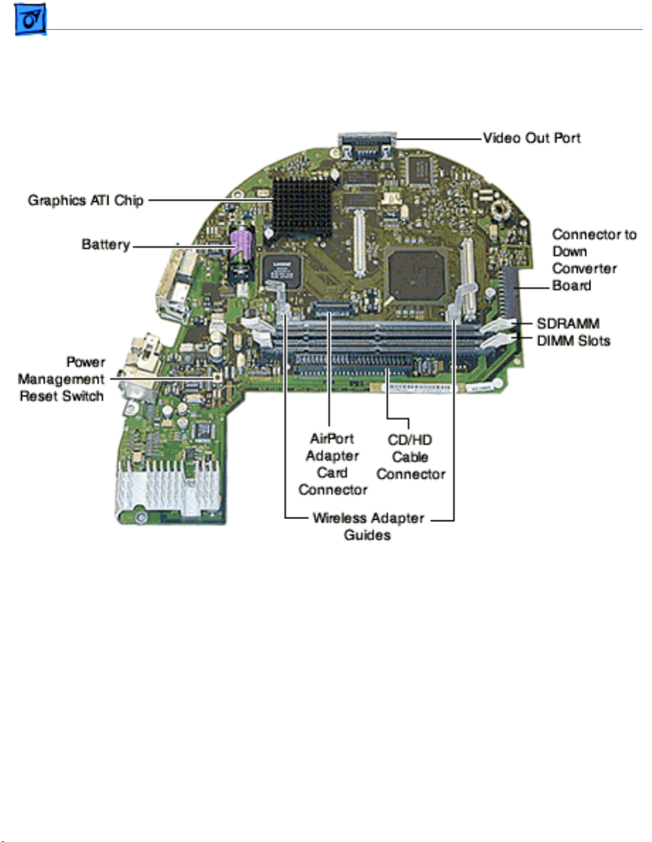
Basics New Features - 6
Logic Board: iMac DV Special Edition, 500 MHz
Page 9

Basics Repair Strategy/Warranty - 7
Repair Strategy/Warranty
Strategy and Ordering
The iMac computers (Summer 2000) include a 1-year
complimentary carry-in warranty. Service the computer
through module exchange and parts replacement. Customers
can request on-site service from an Apple-Authorized
Service Provider Plus (AASP+) Apple Assurance (US
only), or Apple Canada Technical Answerline (Cananda
only).
The parenthetical product description (Summer
Note:
2000) refers to the summer of the Northern Hemisphere.
Page 10

Basics Repair Strategy/Warranty - 8
Apple-service providers planning to support the computer
systems covered in this manual may purchase Service
modules and parts to develop servicing capability. To order
parts, use the AppleOrder (U.S. only) or ARIS (Canada only)
system and refer to the iMac Slot Load CD/DVD Service
Price Pages.
Large businesses, universities, and K-12 accounts must
provide a purchase order on all transactions, including
orders placed through the AppleOrder (U.S. only) or ARIS
(Canada only) system.
Page 11

Basics Repair Strategy/Warranty - 9
USA Ordering
U.S. Service providers not enrolled in AppleOrder may fax
their orders to Service Provider Support (512-908-
8125) or mail them to
Apple Computer, Inc.
Service Provider Support
MS 212-SPS
2323 Ridgepoint Drive
Austin, TX 78754
For US inquiries please call Service Provider Support
(800-919-2775, option1).
Page 12

Basics Repair Strategy/Warranty - 10
Canadian Ordering
Canadian service providers not enrolled in ARIS may fax
their orders to Service Provider Support in Canada (800903-5284).
For Canadian inquiries, please call Service Provider
Support (800-217-9517).
Page 13

K
Service Source
T ak e Apart
iMac, iMac DV, iMac DV+, iMac
DV Special Edition
Page 14

Take Apart - 1
Important: Take Apart Information
The Take Apart procedures for the iMac computers (Summer
2000) are identical to take apart procedures for the slot
loading iMac computers. The slot loading iMac is referenced
in all the pictures in this chapter.
The parenthetical product description (Summer
Note:
2000) refers to the summer of the Northern Hemisphere.
Important:
the power/analog/video board and CRTs. Refer to the take
apart sections for the power/analog/video board and the CRT
for additional information.
The only noticeable
internal
differences are with
Page 15

Take Apart - 2
Tools
The following tools are
recommended for the take
apart procedures:
• phillips screwdriver
(#1 and #2)
• a stubby (short) phillips
screwdriver
• plastic flatblade
screwdriver to release
tabs on plastic housing
• jeweler’s screwdriver
• CRT discharge tool
• needlenose pliers
• ESD mat
Page 16
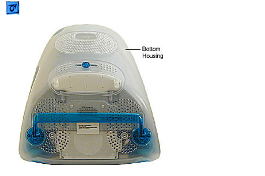
Take Apart Bottom Housing With Flip Foot - 3
Procedures
Bottom Housing With
Flip Foot
Before you begin, position
the computer face down,
resting the computer on an
ESD mat or other soft
surface.
Page 17
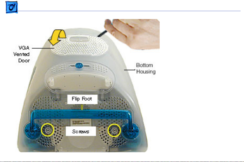
Take Apart Bottom Housing With Flip Foot - 4
1. Using a plastic flatblade
screwdriver, remove
the VGA vented cover.
2. Remove the two screws
near the flip foot.
Page 18

Take Apart Bottom Housing With Flip Foot - 5
3. Remove the video out
access door from the
bottom housing.
Page 19
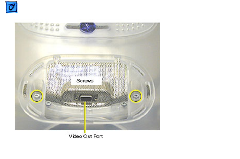
Take Apart Bottom Housing With Flip Foot - 6
4. Remove the two outer
screws located near the
video out port.
Replacement Note:
The bottom housing uses
two sizes of screws. The
two shorter screws
attach near the flip foot.
Page 20
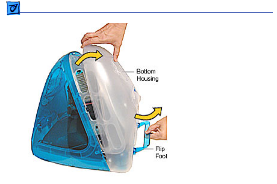
Take Apart Bottom Housing With Flip Foot - 7
5. Pull the bottom housing
off the computer.
Page 21
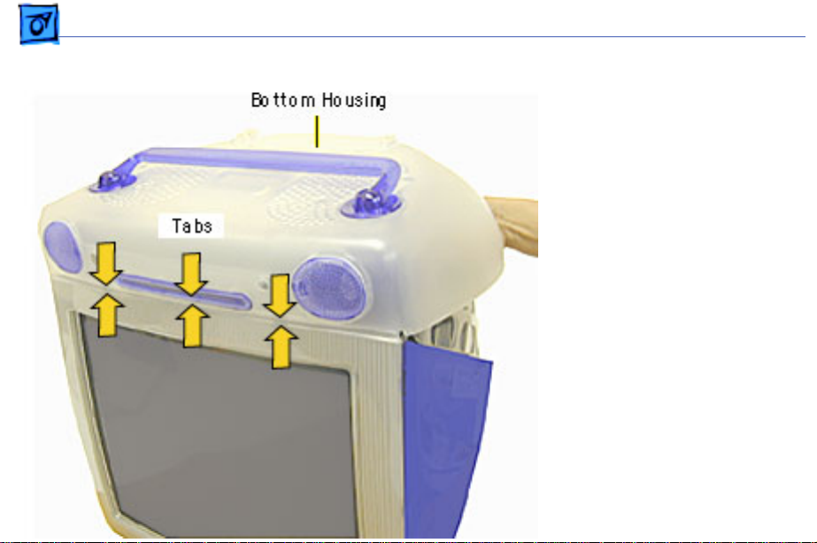
Take Apart Bottom Housing With Flip Foot - 8
Bottom Housing
Replacement Note
1. Align the three tabs on
the bottom housing with
the tab slots on the front
outer bezel.
Ensure that the center
tab is properly aligned
or CDs and DVD discs
may not eject from the
slot.
2. Lower the bottom
housing into place and
replace the screws.
Page 22
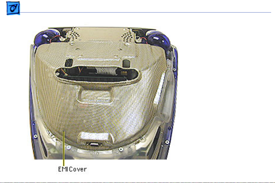
Take Apart EMI Cover - 9
EMI Cover
Before you begin:
• Position the computer
upside down, resting the
computer on an ESD mat
or other soft surface.
• Remove the bottom
housing.
Page 23
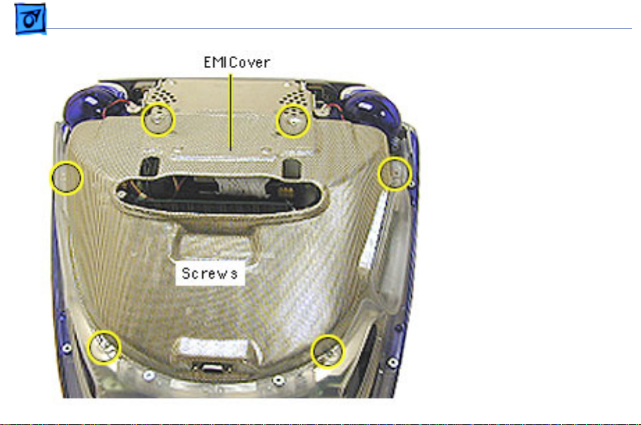
Take Apart EMI Cover - 10
1. Remove the six screws
on the EMI cover.
Page 24
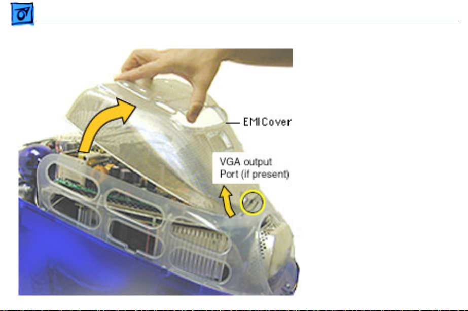
Take Apart EMI Cover - 11
2. Lift the EMI cover off the
computer.
Note:
Be careful of the
VGA output port.
Page 25

Take Apart EMI Cover - 12
Replacement Note:
Position
the rear of the EMI cover
into place first, positioning
the EMI cover over the video
port (if present). Continue
lowering the cover into
place by gently squeezing in
on both sides, as you lower
the cover into position.
Page 26
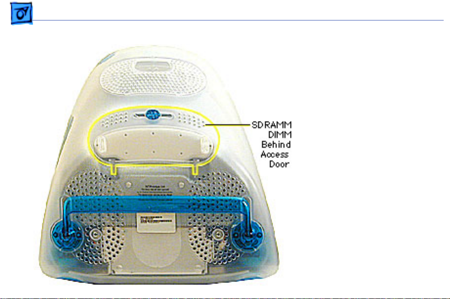
Take Apart SDRAM DIMM - 1 3
SDRAM DIMM
Before you begin, position
the computer face down,
resting the CRT on an ESD
mat or other soft surface.
Page 27
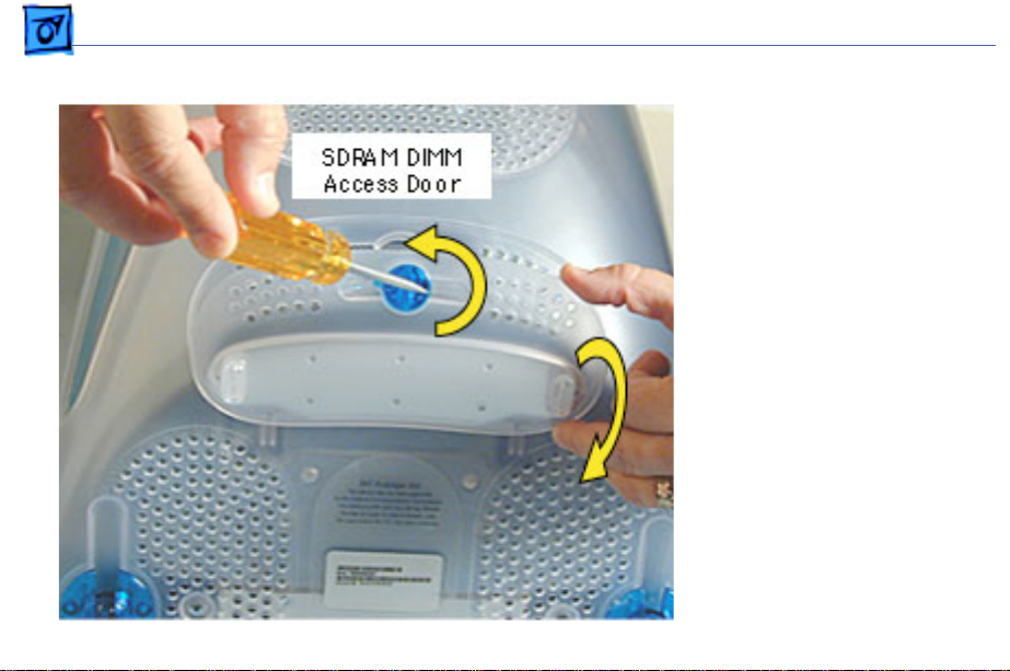
Take Apart SDRAM DIMM - 1 4
1. With a flatbade
screwdriver or coin,
turn the colored latch
counterclockwise on the
access door.
2. Pull the access door
down to open.
Page 28
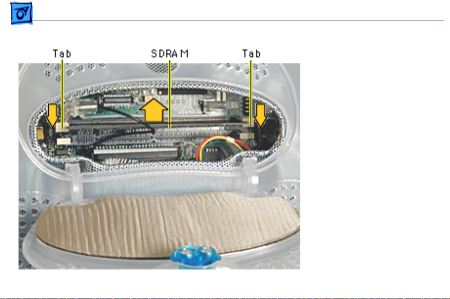
Take Apart SDRAM DIMM - 1 5
3. Push down on the plastic
tabs to release the
SDRAM module(s).
4. Carefully lift the SDRAM
from the slot.
Note:
Remove installed
SDRAM from the logic board
before returning the logic
board to Apple.
Page 29
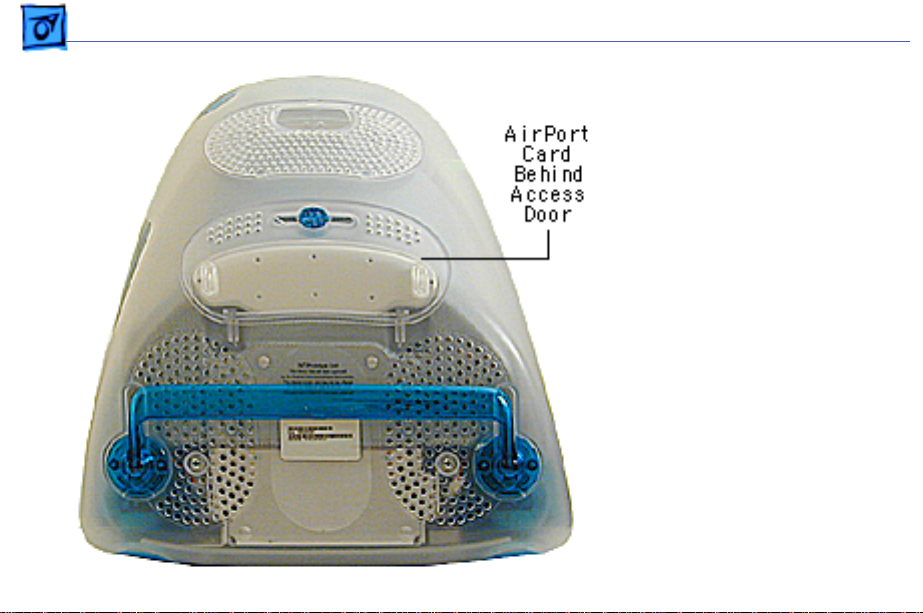
Take Apart AirPort Card - 16
AirPort Card
Before you begin, position
the computer face down,
resting the CRT on an ESD
mat or other soft surface.
If the AirPort Card is
Note:
not installed, a protective
antenna cap will be attached
to the antenna.
Page 30
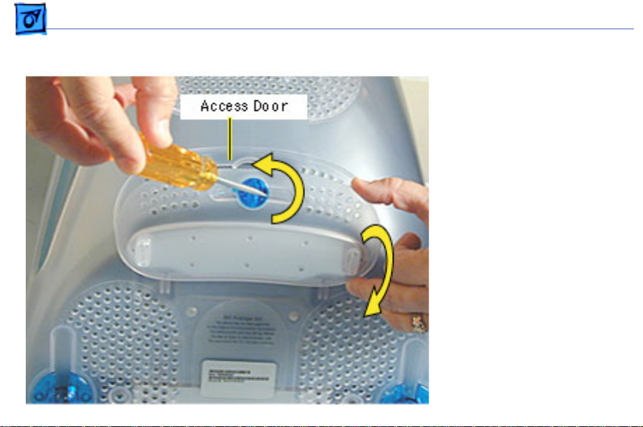
Take Apart AirPort Card - 17
1. With a flatbade
screwdriver or coin,
turn the colored latch to
open the access door.
The antenna and AirPort
Card will be visible
when you open the access
door.
If the AirPort
Note:
card is not installed, a
clear protective antenna
cap will be attached to
the antenna.
Page 31

Take Apart AirPort Card - 18
2. Remove the AirPort Card
by lifting the card
straight up and out of
the card guides and
connector.
Page 32

Take Apart AirPort Card - 19
3. Disconnect the antenna
from the small hole
AirPort Card.
Page 33

Take Apart AirPort Card - 20
4. Remove the ground clip
from the AirPort
Adapter Card.
5. Using the pull tab,
separate the AirPort
Card from the adapter
card.
Page 34

Take Apart CD/HD Carrier - 21
CD/HD Carrier
Before you begin, position
the computer upside down,
resting the computer on an
ESD mat or other soft
surface and remove the
following:
• bottom housing
• EMI cover
• SDRAM
Page 35

Take Apart CD/HD Carrier - 22
1. Remove the four screws
connecting the CD/HD
drive carrier to the the
metal chassis (also
known as the divider
panel).
Page 36

Take Apart CD/HD Carrier - 23
2. Disconnect the following
cables fro the back of the
CD/HD carrier:
• hard drive power
cable
• hard drive data cable
• CD-ROM/DVD-ROM
data cable
• logic board cable
connector
Page 37

Take Apart CD/HD Carrier - 24
3. Tilt the CD/HD carrier
forward and lift the
carrier out of the
computer.
Continue with the
Note:
Take Apart procedures if you
are replacing the CD-ROM,
DVD-ROM, or the hard
drive.
Page 38

Take Apart CD-ROM / DVD-ROM - 2 5
CD-ROM / DVD-ROM
The procedures for
Note:
removing a CD-ROM or
DVD-ROM are identical. This
procedure will reference the
CD-ROM Take Apart.
Before you begin, position
the computer upside down,
resting the computer on an
ESD mat and remove the
following:
• bottom housing
• EMI cover
• SDRAM
• CD/HD carrier
Page 39

Take Apart CD-ROM / DVD-ROM - 2 6
1. Using a Phillips
screwdriver, remove
the CD/HD carrier
mounting screws (two on
each side).
Page 40

Take Apart CD-ROM / DVD-ROM - 2 7
2. Carefully turn the
CD/HD drive carrier
over.
3. Holding onto the CD-ROM
from the rear, lift the
CD-ROM carrier out of
the CD/HD carrier.
Important:
Don’t press
or squeeze the front of
the CD-ROM. Squeezing
the front could bend the
metal housing, making it
impossible to insert or
remove a CD or DVD disc.
Page 41

Take Apart CD-ROM / DVD-ROM - 2 8
4. Using a jeweler’s
screwdriver, remove
the four screws (two on
each side) on the CD/
DVD carrier.
5. Lift the CD-ROM from
its carrier.
Page 42

Take Apart CD-ROM / DVD-ROM - 2 9
6. On the back of the CDROM, Use a jeweler’s
screwdriver to remove
the two screws on the
adapter board.
7. Remove the adapter
board from the CD-ROM.
Return the CD-
Note:
ROM or DVD-ROM drive
to Apple without the
cables, carrier, or the
adapter board. Refer to
the parts database for
more information.
Page 43

Take Apart CD-ROM / DVD-ROM - 3 0
CD-ROM or DVDROM Module
Replacement
Position the CD-ROM or
DVD-ROM into its carrier as
shown.
1. Check that the yellow
warning label is face up.
if you are
Note:
installing a new CD/DVD
carrier, remove the blue
film covering the
grounding pad.
Page 44

Take Apart CD-ROM / DVD-ROM - 3 1
2. Lower the CD/DVD
carrier into the CD/HD
carrier.
3. Push the CD/DVD
carrier forward so the
carrier tabs go through
the holes on the CD/HD
carrier.
4. Replace the CD/HD
carrier screws.
Page 45

Take Apart CD-ROM / DVD-ROM - 3 2
5. Holding the drive
carrier in the
orientation shown, make
sure the CD-ROM or
DVD-ROM is correctly
installed into the CD/HD
carrier.
6. Make sure the Slave/
Master switch on the
back of the drive is still
set to the Slave mode
(set to the left).
Page 46

Take Apart CD/DVD Adapter Board - 3 3
CD/DVD Adapter
Board
Before you begin, position
the computer upside down,
resting the computer on an
ESD mat or other soft
surface and remove the
following:
• bottom housing
• EMI cover
• SDRAM
• CD/HD carrier
Page 47

Take Apart CD/DVD Adapter Board - 3 4
1. Using a jeweler’s
screwdriver, remove
the two screws on the
CD/DVD adapter board.
2. Remove the adapter
board from the back of
the CD-ROM.
Note:
Return the CD/DVDROM drive to Apple without
the cables, carrier, or the
adapter board. Refer to the
parts database for more
information.
Page 48

Take Apart Hard Drive - 35
Hard Drive
Before you begin, position
the computer upside down,
resting the computer on an
ESD mat or other soft
surface and remove the
following:
• bottom housing
• EMI cover
• SDRAM
Page 49

Take Apart Hard Drive - 36
1. Disconnect the following
cables on the back of the
hard drive:
• Hard drive power
cable
• Hard drive data cable
Page 50

Take Apart Hard Drive - 37
The hard drive
Note:
carrier shown was
removed from the
computer. However, you
can easily remove the
hard drive while the
carrier is still screwed
down to the chassis.
Continue with the
procedure.
2. Using a #1 Phillips
screwdriver, remove
the four hard drive
mounting screws.
Page 51

Take Apart Hard Drive - 38
3. Slide the hard drive out
of the CD/HD carrier.
Return the drives
Note:
without the cables or
carriers. Exchange Apple
hard drive modules likefor-like in Apple packaging.
Failure to comply with this
requirement may result in a
packaging noncompliance
charge. Refer to the parts
database for more
information.
Page 52

Take Apart Hard Drive - 39
Hard Drive Replacement
When installing the hard
drive into the CD/HD
carrier, make sure the hard
drive is component side up
(as shown).
Page 53

Take Apart Logic Board - 40
Logic Board
Before you begin, position
the computer upside down,
resting the computer on an
ESD mat or other soft
surface and remove the
following:
• bottom housing
• EMI cover
The logic board and the down
converter board are
removed together (still
connected to each other), and
are separated once they are
removed from the computer.
Page 54

Take Apart Logic Board - 41
Remove SDRAM to
Note:
make cable removal easier.
1. On the back of the CD/HD
carrier,disconnect the:
• hard drive power
cable
• hard drive data cable
• CD-ROM/DVD-ROM
data cable
• logic board cable
connector
2. Disconnect the antenna if
it’s connected to the
AirPort Card, or it it’s
attached to the protective
antenna cap.
Page 55

Take Apart Logic Board - 42
3. Remove the six screws
on the logic board and
five screws on the down
converter board.
Note:
The two screws
located at the top of the
down converter board
(near the speaker) are
larger screws than the
other screws (with
washers).
Page 56

Take Apart Logic Board - 43
4. Gently lift the down
converter board and
logic board out of the
computer.
Page 57

Take Apart Logic Board - 44
5. Using a flatblade
screwdriver, pry the
plastic rivet off the
board.
Put the top half of the
rivet back into the
bottom half so it doesn’t
get lost.
Page 58

Take Apart Logic Board - 45
6. Holding onto the down
converter, press down
on the black connector to
separate the down
converter board from
the logic board.
If you are returning
Note:
the logic board to Apple
refer to the parts database
and remove the SDRAM, any
cables, the modem, the
AirPort Card, and I/O panel.
Replacement Note:
When
reinstalling the logic board,
make sure the antenna wire
is not underneath the board .
Page 59

Take Apart Down Converter Board - 4 6
Down Con verter Board
Before you begin, position
the computer upside down,
resting the computer on an
ESD mat or other soft
surface and remove the
following:
• bottom housing
• EMI cover
The logic board and
Note:
the down converter board
are removed together (still
connected to each other), and
are separated once they are
removed from the computer.
Page 60

Take Apart Down Converter Board - 4 7
Remove SDRAM to
Note:
make cable removal easier.
1. On the back of the CD/HD
carrier, disconnect the:
• hard drive power
cable
• hard drive data cable
• CD-ROM/DVD-ROM
data cable
• logic board cable
connector
2. Disconnect the antenna if
it’s connected to the
AirPort Card, or it it’s
attached to the protective
antenna cap.
Page 61

Take Apart Down Converter Board - 4 8
3. Remove the six screws
on the logic board and
five screws on the down
converter board.
Note:
The two down
converter screws located
near the speaker are
larger screws than the
rest of the down
converter screws.
Page 62

Take Apart Down Converter Board - 4 9
4. Lift the boards out of the
computer.
Page 63

Take Apart Down Converter Board - 5 0
5. Using a flatblade
screwdriver, pry the
rivet off the logic board.
Put the top half of the
rivet back into the
bottom half so it doesn’t
get lost.
Page 64

Take Apart Down Converter Board - 5 1
6. Holding onto the boards,
press down on the black
connector and separate
the down converter
board from the logic
board.
Replacement Note:
When
reinstalling the logic
board, make sure the
antenna wire is not
underneath the board.
Page 65

Take Apart Modem - 5 2
Modem
Before you begin, position
the computer upside down,
resting the computer on an
ESD mat or other soft
surface and remove the
following:
• bottom housing
• EMI cover
• logic board
The modem is located
Note:
on the underside of the logic
board.
Page 66

Take Apart Modem - 5 3
1. With the logic board
facing right side up,
disconnect the cable at
J12.
2. Remove the two screws
on the I/O panel.
Page 67

Take Apart Modem - 5 4
3. Turn the logic board to
the underside and
remove the modem
screw.
Page 68

Take Apart Modem - 5 5
4. Rotate the logic board
right side up again.
Carefully slide the I/O
panel off the logic board.
Note: As you slide the I/
O panel off the logic
board, support the
modem with your other
hand so the modem
doesn’t fall off the logic
board.
5. Remove the modem from
its connector slot on the
underside of the logic
board.
Page 69

Take Apart Modem - 5 6
Modem Replacement
The I/O panel and the modem
are sandwiched between the
logic board and the metal
frame of the I/O panel. The
metal frame fits on top of the
logic board, over the screw
holes. On the underside of
the logic board, the screw
tab goes under the modem.
Replacement Note: After
replacing an international
modem, use the Modem
Country Selector utility to
set the modem to the correct
country.
Page 70

Take Apart I/O Panel - 57
I/O Panel
Before you begin, position
the computer upside down,
resting the computer on an
ESD mat or other soft
surface and remove the
following:
• bottom housing
• EMI cover
• logic board
Page 71

Take Apart I/O Panel - 58
1. Disconnect the cable at
J12, going from the
logic board to the I/O
panel.
2. Remove the two screws
on the I/O panel.
Page 72

Take Apart I/O Panel - 59
3. Turn the logic board
over and remove the
modem screw.
Page 73

Take Apart I/O Panel - 60
4. Rotate the logic board
face up again and
carefully slide the I/O
panel off the logic board.
Note: As you slide the I/
O panel off the logic
board, support the
modem with your hand so
the modem doesn’t fall
off the logic board.
Page 74

Take Apart Front Outer Bezel - 61
Front Outer Bezel
Before you begin, place the
computer on an ESD mat and
remove the bottom housing.
Page 75

Take Apart Front Outer Bezel - 62
1. With a jeweler’s
screwdriver, carefully
remove the two tabs on
the front outer bezel.
Refer to the next graphic
for a close-up of the tab
removal.
Page 76

Take Apart Front Outer Bezel - 63
2. After removing the tabs,
remove the screws
located under the tabs.
Page 77

Take Apart Front Outer Bezel - 64
Note: The bezel tabs fit
tightly into the rear
housing. A good, hard pull
upward is required to
release all the tabs.
3. Insert a plastic tool
underneath the bezel.
4. Pry the outer bezel tabs
from the rear housing
with a plastic tool. As
you push and pry the tool
inside the bezel, the side
tabs will start to
release.
5. Insert the tool on the left
side of the bezel and
repeat.
Page 78

Take Apart Front Outer Bezel - 65
6. As the tabs start to
release, pull hard on the
front outer bezel to
release the tabs
completely.
Page 79

Take Apart Top Rear Housing - 6 6
Top Rear Housing
±Warning: This product
contains high voltage and a
high-vacuum picture tube.
To prevent serious injury,
review CRT safety. From the
Service Source Online home
page, click Troubleshoot and
Repair. Then click on Safety
under the Tools list.
Before you begin, rest the
computer on an ESD mat and
remove the following:
• bottom housing
• front outer bezel
Page 80

Take Apart Top Rear Housing - 6 7
1. Remove the two tabs
(screw caps) on the top
inner bezel. Refer to the
next page for a close-up
of the tab removal.
Page 81

Take Apart Top Rear Housing - 6 8
2. Pry the tabs off, and
remove the two screws
under each tab.
Page 82

Take Apart Top Rear Housing - 6 9
3. Position the computer
face down.
4. Remove four screws and
loosen the fixed screw
(at the top) on the rear
housing.
Page 83

Take Apart Top Rear Housing - 7 0
5. Position the computer
right side up. Push down
and pull out on the rear
housing to unhook the
rear housing tabs that
connect to the inner
bezel.
Page 84

Take Apart Top Rear Housing - 7 1
6. Lift the top rear housing
off the computer.
Page 85

Take Apart Divider Panel - 72
Divider Panel
Many service parts, such as
the speakers, power/
analog/video board, side
panels, cables, and the
headphone board, are
connected to the divider
panel. The divider panel is
the metal chassis with EMI
foam, part number 9224044, shown on the next
page.
Page 86

Take Apart Divider Panel - 73
This is the divider panel,
service part number 922-
4044.
Page 87

Take Apart Power/Analog/Video Board - 74
Power/Analog/Video
Board
Before you begin, discharge
the CRT, rest the computer
on an ESD mat or other soft
surface and remove the
following:
• bottom housing
• front outer bezel
• top rear housing
Note: There are two power/
analog/video boards, part
number 661-2347 (with a
switch at SW901) and 661-
2370. Refer to “Identifying
the Power/Analog Boards”
Page 88

Take Apart Power/Analog/Video Board - 75
mentioned later in this
chapter.
Page 89

Take Apart Power/Analog/Video Board - 76
±Warning: This product
contains high voltage and a
high-vacuum picture tube.
To prevent serious injury,
discharge the CRT.
1. Disconnect the
microphone connector
located near the top of
the CRT.
2. Unwrap the bendable
cable wraps in the upper
left and upper right
corners of the CRT.
3. Disconnect the anode cap.
Page 90

Take Apart Power/Analog/Video Board - 77
4. Lift the degauss cable out
of the way to access the
side panel screws.
5. Using a narrow shaft
screwdriver, remove
the four side panel
screws (two on each
side) that attach the left
and right side panels to
the inner bezel.
Page 91

Take Apart Power/Analog/Video Board - 78
6. Open the CRT cable
clamps. Remove the
wires from the cable
clamps.
Page 92

Take Apart Power/Analog/Video Board - 79
7. Partially lift the side
panels (with the power/
analog/video board
attached to the divider
panel) up and off the
inner bezel to gain
access to connector
P501 located at the
bottom of the power/
analog/video board.
Page 93

Take Apart Power/Analog/Video Board - 80
8. Disconnect P501 and
P701 on the power/
analog/video board. The
cables are located near
the high voltage
capacitor.
Page 94

Take Apart Power/Analog/Video Board - 81
9. On the other side of the
CRT neck, disconnect the
brown degauss cable,
P901, from the power/
analog/video board.
Remove P901 from the
cable clamp.
Page 95

Take Apart Power/Analog/Video Board - 82
10. At the very bottom of the
power/analog/video
board, near the bottom of
the CRT, disconnect
P902, which is part of
the audio/headphone/
LED/speaker cable
assembly.
Page 96

Take Apart Power/Analog/Video Board - 83
11. Disconnect the two
ground cables on the
video board.
Caution: Be careful when
working around the CRT
neck rings. If the neck rings
are bumped, the CRT will be
knocked out of adjustment,
and will require
replacement of the CRT.
Page 97

Take Apart Power/Analog/Video Board - 84
12. Loosen the CRT neck
clamp screw.
Page 98

Take Apart Power/Analog/Video Board - 85
13. Carefully pull the video
board off the CRT neck.
Page 99

Take Apart Power/Analog/Video Board - 86
14. Holding on to the side
panels, lift the power/
analog/video board
(which is attached to the
side panels and
dividerpanel) from the
inner bezel.
Page 100

Take Apart Power/Analog/Video Board - 87
15. Remove the ten screws
and pinch the two
standoffs with a
needlenose pliers to lift
the power/analog board
off the divider panel.
 Loading...