

Page 1
K
Service Source
Apple High-Res
Monochrome Monitor
Page 2
K
Service Source
Specifications
Apple High-Resolution
Monochrome Monitor
Page 3

Specifications Characteristics - 1
Characteristics
Picture Tube
Screen Resolution
Scan Rates
Active V ideo Display Area
12-in. diagonal screen
Phosphor EIA Type P4 (white)
Flat, high-contrast, antiglare surface
640x480; 76 dpi
Vertical refresh rate: 66.7 Hz
Horizontal scan rate: 35.0 kHz
8.38 in. by 6.3 in. (213 mm by 160 mm)
Page 4

Specifications Characteristics - 2
Input Signal
Video: analog; RS-343 standard
Page 5

Specifications Controls - 3
Controls
User Controls
Rear panel: power switch
Right side: brightness and contrast controls
Page 6

Specifications Physical and Electrical - 4
Physical and Electrical
Power Supply
Size and Weight
Universal power supply
Voltage: 85–270 VAC
Frequency: 50–60 Hz
Power: 40 W maximum
Height: 10 in. (254 mm)
Width: 12.2 in. (310 mm)
Depth: 14.4 in. (365 mm)
Weight: 17 lb. (7.7 kg)
Page 7

Specifications Operating Environment - 5
Operating Environment
Temperature
Humidity
Altitude
50°C–l04°F (l0°C–40°C)
90% maximum, noncondensing
10,000 ft. (3,048 m) maximum
Page 8

K
Service Source
Troubleshooting
Apple High-Resolution
Monochrome Monitor
Page 9

Troubleshooting General/ - 1
General
The Symptom Charts included in this chapter will help you
diagnose specific symptoms related to your product. Because cures
are listed on the charts in the order of most likely solution, try
the first cure first. Verify whether or not the product continues to
exhibit the symptom. If the symptom persists, try the next cure.
(Note: If you have replaced a module, reinstall the original module
before you proceed to the next cure.)
If you are not sure what the problem is, or if the Symptom Charts
do not resolve the problem, refer to the Flowchart for the product
family.
For additional assistance, contact Apple Technical Support.
Page 10
Troubleshooting Symptom Charts/No Raster - 2
Symptom Charts
No Raster
No raster, LED off 1 Ensure monitor’s video cable is connected to the computer or
the video card in the computer.
2 Verify that power cord is connected.
3 Check internal power connectors.
4 Replace fuse.
5 Replace power supply.
6 Replace power switch.
No raster, LED on 1 Ensure monitor’s video cable is connected to the computer or
the video card in the computer.
2 Adjust brightness and contrast knobs.
3 Replace video card (if present) in computer.
4 Adjust sub-brightness (cutoff) control.
5 Check logic board connection to power supply.
6 Replace fuse.
7 Replace main board.
8 Replace power supply.
9 Replace power switch assembly.
10 Replace video board C.
11 Replace contrast control board.
Page 11

Troubleshooting Symptom Charts/Geometry - 3
Geometry
Raster stretched or
compressed on side or
top of screen
1 Verify that distortion is not due to environmental conditions.
2 Perform appropriate geometric adjustments.
3 Replace main board.
4 Replace CRT.
Page 12

Troubleshooting Symptom Charts/Synchronization - 4
Synchronization
Picture breaks into
diagonal lines
Picture rolls
vertically
One horizontal or
vertical line appears
on screen
1 Connect another monitor to computer and verify presence of
video signal.
2 Replace main board.
1 Verify that video card in computer is working properly.
2 Adjust vertical hold.
3 Check connector on I/O connector board.
4 Replace main board.
1 Check yoke connectors.
2 Replace main board.
3 Replace CRT.
Page 13
Troubleshooting Symptom Charts/Video - 5
Video
Picture too dark or
too bright
Brightness
unadjustable
Out of focus 1 Perform focus adjustments.
1 Adjust brightness knob.
2 Verify that video card in computer is working properly.
3 Adjust sub-brightness (cutoff) control.
4 Replace main board.
5 Replace video board C.
6 Replace CRT.
1 Replace contrast control board.
2 Replace main board.
3 Replace video board C.
4 Replace CRT.
2 Replace main board.
3 Replace video board C.
4 Replace CRT.
Page 14

Troubleshooting Symptom Charts/Miscellaneous - 6
Miscellaneous
Picture jitters 1 Check grounding cable connections to chassis.
2 Confirm that adjacent computer equipment is properly
grounded. Move electrical devices away from monitor.
Temporarily shut off fluorescent lights in area.
3 Replace main board.
Flashing lines on
screen
Black spots on screen
(burnt phosphors)
1 Confirm contact of video connector to neck of CRT.
2 Replace contrast control board.
3 Replace main board.
Replace CRT.
Page 15
K
Service Source
T ak e Apart
Apple High-Resolution
Monochrome Monitor
Page 16
Take Apart Rear Cover - 1
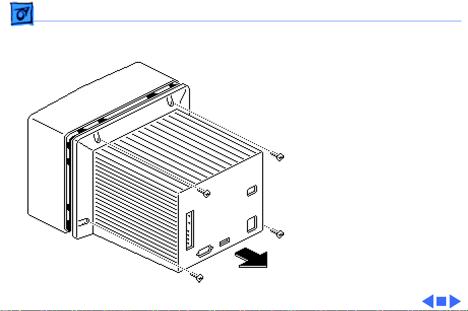
Rear Cover
No preliminary steps are
required before you begin
this procedure.
Remove the four case screws
and lift off the rear cover.
Page 17
Take Apart Main Board - 2
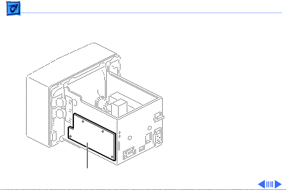
Main Board
Before you begin:
• Remove the rear cover
• Discharge the CRT
±
Main Board
Warning:
contains high voltage and a
high-vacuum picture tube.
To prevent serious injury,
review CRT safety in
Bulletins/Safety.
±
Warning:
grounding wriststrap until
after discharging the CRT.
This product
Never use a
Page 18
Take Apart Main Board - 3
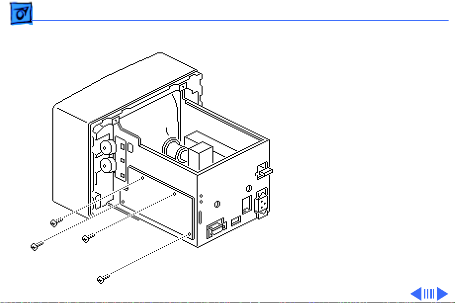
1 Remove the four screws
that fasten the main
board to the chassis.
Page 19
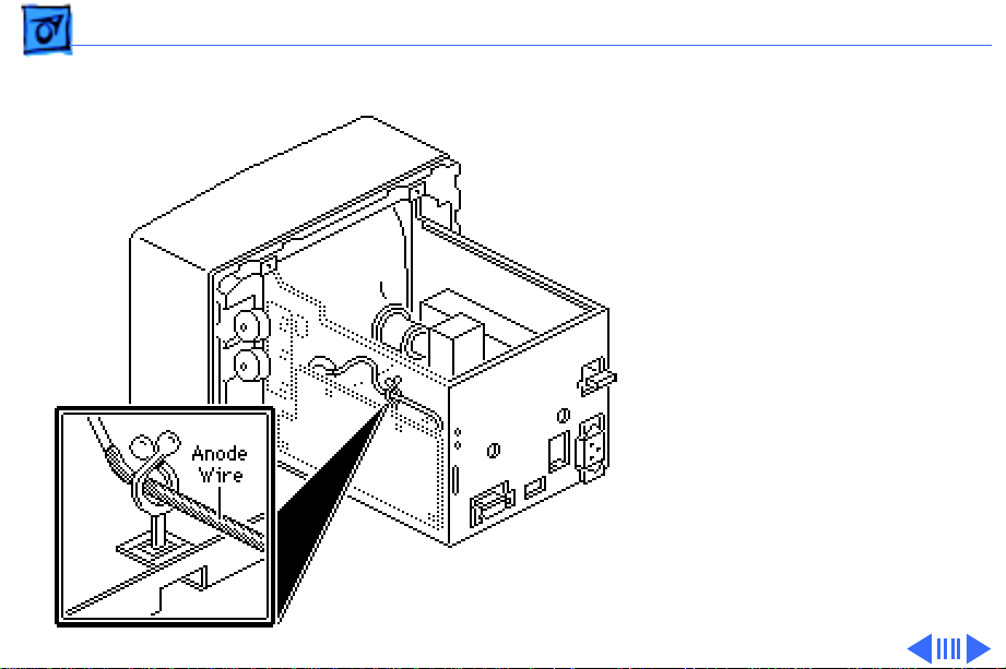
Take Apart Main Board - 4
2 Remove the anode wire
from the cable clamp.
Page 20
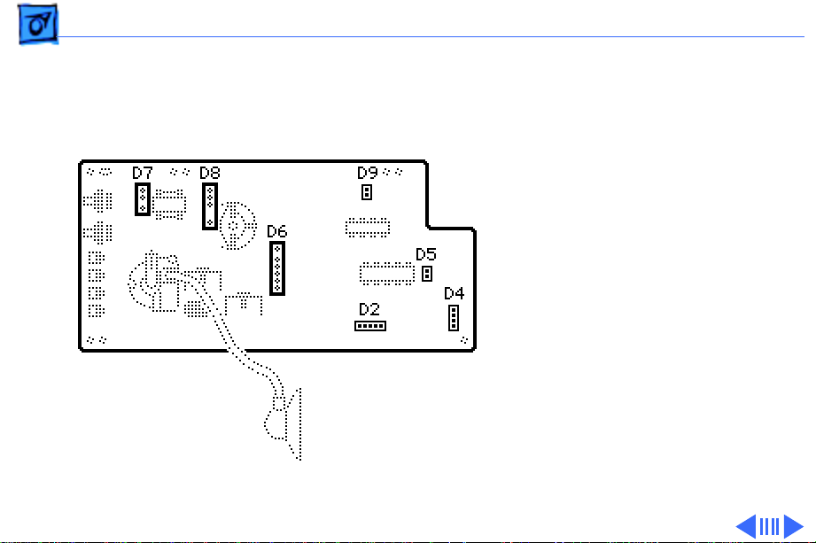
Take Apart Main Board - 5
Note:
Connectors D2, D4,
D5, and D9 fit tightly and
are difficult to reach, so
pull the main board away
from the chassis before you
try to remove these
connectors.
3 Remove the following
cable connectors from
the main board:
• D7 (large 3-pin
connector)
• D8 (large 4-pin
connector)
• D6 (large 6-pin
connector)
Page 21
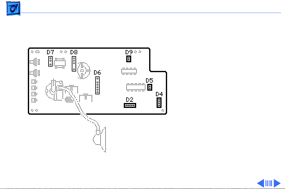
Take Apart Main Board - 6
• D9 (2-pin connector)
• D2 (5-pin connector)
• D5 (2-pin connector)
• D4 (4-pin connector)
Page 22
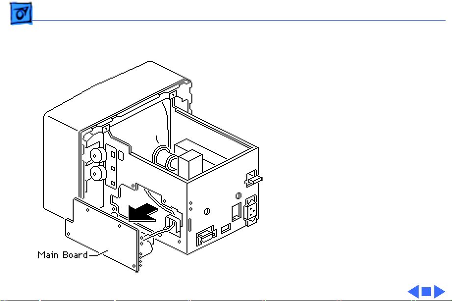
Take Apart Main Board - 7
4 Lift the main board
from the chassis.
Page 23

Take Apart Power Supply - 8
Power Supply
Before you begin:
• Remove the rear cover
• Discharge the CRT
±
Warning:
contains high voltage and a
high-vacuum picture tube.
To prevent serious injury,
review CRT safety in
Bulletins/Safety.
±
Warning:
grounding wriststrap until
after discharging the CRT.
This product
Never use a
Page 24

Take Apart Power Supply - 9
Note:
To disconnect the 3pin connector from the
power supply, you may need
to remove tie-wraps from
the power supply cable.
Then lift the chassis and
6-Pin
reach beneath the power
supply.
1 Disconnect the 6-pin
connector and the 3-pin
connector from the rear
3-Pin
of the power supply.
2 Release the CRT ground
wire from the plastic
cable clamp on the side
of the power supply.
Page 25

Take Apart Power Supply - 10
3 Remove the two power
supply mounting screws.
4 Lift the power supply
until its tabs clear the
holes in the chassis and
remove the power
supply.
Page 26

Take Apart Fuse - 11
Fuse
Before you begin:
• Remove the rear cover
• Discharge the CRT
• Remove the power supply
±
Warning:
contains high voltage and a
high-vacuum picture tube.
To prevent serious injury,
review CRT safety in
Bulletins/Safety.
±
Warning:
grounding wriststrap until
after discharging the CRT.
This product
Never use a
Page 27

Take Apart Fuse - 12
1 Remove the two screws
from the sides of the
power supply housing
and the screw in the
indentation on the
bottom.
2 Slide the power supply
board from the power
supply housing.
Replacement Note:
replacing the power supply
board, make sure it slides
into the middle slot on the
side of the housing. The
board should not touch the
bottom of the housing.
When
Page 28

Take Apart Fuse - 13
3 If the wire inside the
fuse is broken, replace
the fuse (250 V, 2 A).
Page 29

Take Apart Contrast Control Board - 14
Contrast Control Board
Before you begin:
• Remove the rear cover
• Discharge the CRT
±
Contrast Control Board
Warning:
contains high voltage and a
high-vacuum picture tube.
To prevent serious injury,
review CRT safety in
Bulletins/Safety.
±
Warning:
grounding wriststrap until
after discharging the CRT.
This product
Never use a
Page 30

Take Apart Contrast Control Board - 15
1 Remove the wires from
the four cable clamps.
Page 31

Take Apart Contrast Control Board - 16
2 Disconnect the upper,
middle, and lower
connectors from the
contrast control board,
and pull off the two
knobs.
Contrast Control
Board
3 Remove the two
mounting screws and
lift out the contrast
control board.
Connectors
Page 32

Take Apart Video Board C - 17
Video Board C
Before you begin:
• Remove the rear cover
• Discharge the CRT
±
Warning:
contains high voltage and a
high-vacuum picture tube.
To prevent serious injury,
review CRT safety in
Bulletins/Safety.
±
Warning:
grounding wriststrap until
after discharging the CRT.
This product
Never use a
Page 33

Take Apart Video Board C - 18
Video Board C
Replacement Note:
Video
board C is in a metal box.
When replacing a defective
board, retain the back cover
of the metal box and send the
rest of the module, including
cables, back to Apple.
1 Pull off the back of the
metal box that holds
video board C.
Page 34

Take Apart Video Board C - 19
2 Remove the cables from
the four plastic clamps.
Page 35

Take Apart Video Board C - 20
3 Disconnect connectors
D2 and D7 from the logic
board.
Page 36

Take Apart Video Board C - 21
4 Di sconnect the cable at
location V-5 from the
contrast control board.
V5
Page 37

Take Apart Video Board C - 22
5 Disconnect the two black
cables from the bottom
of video board C at their
midpoint connectors.
Connector
Connector
Page 38

Take Apart Video Board C - 23
Caution:
or applying force to video
board C could damage the
neck of the CRT. Be sure to
pull video board C straight
off the neck of the CRT.
6 Firmly grasp video
Twisting, bending,
board C to support the
neck of the CRT and
loosen the screw on the
metal clamp that holds
video board C to the CRT.
Page 39

Take Apart Video Board C - 24
Caution:
the metal clamp is sticky
and difficult to loosen, use
an art knife to very
carefully cut away the tape.
Do not put pressure on the
neck of the CRT.
7 Carefully pull video
If the tape under
board C straight off the
neck of the CRT.
Page 40

Take Apart CRT - 25
CRT
Before you begin:
CRT
• Remove the rear cover
• Discharge the CRT
• Remove video board C
±
Warning:
contains high voltage and a
high-vacuum picture tube.
To prevent serious injury,
review CRT safety in
Bulletins/Safety.
±
Warning:
grounding wriststrap until
after discharging the CRT.
This product
Never use a
Page 41

Take Apart CRT - 26
1 Disconnect the two-pin
connector from location
D9 on the main board.
Page 42

Take Apart CRT - 27
2 Remove the six chassis
mounting screws and
pull the chassis off the
bezel.
Page 43

Take Apart CRT - 28
3 Remove the four CRT
mounting screws and
lift the CRT out of the
bezel.
Ground Strap
and Spring
Replacement Note:
are replacing a defective
CRT, remove the ground
strap and the spring.
Reinstall them on the
replacement CRT.
±
Warning:
dispose of the CRT, refer to
the CRT disposal
instructions in Bulletins/
Safety.
If you need to
If you
Page 44

Take Apart LED Cable Assembly - 29
LED Cable Assembly
Before you begin:
• Remove the rear cover
• Discharge the CRT
±
Warning:
contains high voltage and a
high-vacuum picture tube.
To prevent serious injury,
review CRT safety in
Bulletins/Safety.
±
Warning:
grounding wriststrap until
after discharging the CRT.
This product
Never use a
Page 45

Take Apart LED Cable Assembly - 30
1 Disconnect the two-pin
connector from location
D9 on the main board.
2 Remove the cable from
the cable clamps.
Page 46

Take Apart LED Cable Assembly - 31
3 Remove the LED
mounting screw and lift
the LED assembly free.
LED Assembly
Page 47

Take Apart Power Switch - 32
Power Switch
Before you begin:
• Remove the rear cover
• Discharge the CRT
±
Warning:
contains high voltage and a
high-vacuum picture tube.
To prevent serious injury,
review CRT safety in
Bulletins/Safety.
±
Warning:
grounding wriststrap until
after discharging the CRT.
This product
Never use a
Page 48

Take Apart Power Switch - 33
1 Pull the plastic knob
from the power switch
stem.
2 Remove the two screws
from the metal bracket.
Page 49

Take Apart Power Switch - 34
3 Remove the two wires
from the plastic cable
clamp and desolder the
wires from the switch.
Page 50

K
Service Source
Adjustments
Apple High-Resolution
Monochrome Monitor
Page 51

Adjustments Geometry - 1
Geometry
No preliminary steps are
required before you begin
this procedure.
±
Warning:
contains high voltage and a
high-vacuum picture tube.
To prevent serious injury,
review CRT safety in
Bulletins/Safety.
Adjustment
Controls
Contrast and
Brightness
Controls
This product
Page 52

Adjustments Geometry - 2
±
Warning:
must make adjustments
from the rear of the
computer, position a mirror
to view the computer screen.
Do not reach around the
computer to make
adjustments.
Note:
Do not attempt yoke
adjustments on this monitor.
The geometry adjustment
controls are behind the
service access panel.
Geometry adjustments may
be necessary whenever you
replace the main deflection
board, CRT, or video board.
Because you
Page 53

Adjustments Geometry - 3
Set the contrast knob to
maximum and the brightness
knob to the center (detent)
position.
Brightness
Contrast
Page 54

Adjustments Geometry - 4
Horizontal Size
Note:
Always adjust the
horizontal size before you
adjust the vertical size. The
horizontal adjustment can
affect the height of the
raster.
1 Use Display Service
Utility to display the
Crosshatch II (white
background) test
pattern.
Page 55

Adjustments Geometry - 5
2 Using a plastic
screwdriver, adjust the
horizontal size control
until the raster is 8.4
inches (213.5 mm)
wide.
Page 56

Adjustments Geometry - 6
Vertical Size
Note:
Always adjust the
horizontal size before you
adjust the vertical size. The
horizontal adjustment can
affect the height of the
raster.
Using the Crosshatch II test
pattern and a plastic
screwdriver, adjust the
vertical size control until
the raster is 6.3 inches
(160 mm) high.
Ê
Page 57

Adjustments Focus - 7
Focus
1 Use Display Service
Utility to display the
Focus test pattern.
2 Using a plastic
screwdriver, adjust the
focus control for the best
clarity at the center of
the screen.
Focus
Page 58

Adjustments Video - 8
Video
Before you begin:
• Remove the rear cover
• Connect the video cable
• Connect the power cord
±
Warning:
contains high voltage and a
high-vacuum picture tube.
To prevent serious injury,
review CRT safety in
Bulletins/Safety.
This product
Contrast and
Brightness
Controls
Subcontrast Control
Adjustment
Controls
Page 59

Adjustments Video - 9
±
Warning:
must make adjustments
from the rear of the
computer, position a mirror
to view the computer screen.
Do not reach around the
computer to make
adjustments.
Note:
After you replace the
contrast control board, main
deflection board, or video
board, you may need to
perform video adjustments.
Because you
Page 60

Adjustments Video - 10
Subcontrast
1 Using a plastic
screwdriver two inches
in length, adjust the
subcontrast control
until the control is
midway between the high
and low stops.
Subcontrast
Page 61

Adjustments Video - 11
2 Make sure the Control
Panel is set to 16 Grays.
3 Use Display Service
Utility to display the
Gray Bars test pattern.
4 Set the contrast knob to
maximum and the
brightness knob to the
center (detent) position.
Brightness
Contrast
Page 62

Adjustments Video - 12
5 If you adjust the cutoff
control (RV506) up
(clockwise) too far, the
monitor may shut down.
If this happens, turn off
the monitor and turn
down the cutoff control
fully counterclockwise.
Wait 30 seconds, turn on
the monitor, and resume
the adjustment.
Using the plastic
screwdriver, adjust the
cutoff control until the
Cutoff
leftmost bar is black
and the second bar is
just visible.
Page 63

Adjustments Video - 13
Cutoff
Cutoff
All-White Screen
Important:
light meter models R77,
L-248, and 246 differ.
Please note which meter
you are using before making
adjustments. (See “Light
Meter Setup.”)
1 Using Display Service
Utility, display the AllWhite Screen test
pattern.
Readings from
Page 64

Adjustments Video - 14
2 Using the light meter and
a plastic screwdriver,
adjust the cutoff control
until you get 33 foot
All-White Screen
lamberts (± 3 foot
lamberts), which on the
light meter is
• Model R77: 25 on the
bottom scale
• Model L-248: middle
of the 10 scale
• Model 246: 25 on the
red scale
Cutoff
Important:
Over time, light
meter tolerances can vary.
If you doubt your meter’s
accuracy, verify the
Page 65

Adjustments Video - 15
readings with a known-good
light meter or photometer.
Page 66

Adjustments Light Meter Setup - 16
Light Meter Setup
This topic covers setup for
three light meter models:
R77, L-248, and 246.
Model R77 (Apple part
number 076-0310) is the
newest model available.
Model R77
The R77 light meter is
capable of reading luminance
from 10 to 1,000
footcandles (fc).
Before you begin, remove
the 10X multiplier plate
Page 67

Adjustments Light Meter Setup - 17
from the lens.
Three scales are shown on
the light meter:
• 200-1000 fc
• 50-250 fc
• 10-50 fc
Because display screen
luminance typically ranges
from 10 to 50 fc, take
readings from the bottom
scale only.
Page 68

Adjustments Light Meter Setup - 18
To measure a display
screen’s luminance,
1 Set the scale switch to
the bottom position (to
set up the 10-50 fc
scale).
2 Place the lens against the
middle of the screen and
read the bottom scale.
Note:
When the light meter
is not in use, slide the scale
switch to its top position,
and store the meter in its
protective case.
Important:
light meter is giving false
If you suspect the
Page 69

Adjustments Light Meter Setup - 19
readings, verify the
readings with a known-good
light meter or photometer.
Also check the age of the R77
light meter by its four-digit
manufacturing date stamp
(such as 0398 for March
1998).
Caution:
meter can permanently
damage its accuracy. A
shock-damaged meter might
read incorrectly or its
pointer may not drop to
zero.
Dropping the
Page 70

Adjustments Light Meter Setup - 20
Side Switch
Scale
Lens
Read Button
Red Area
Model L-248
1 Press the red button on
the back of the light
meter. If the reading is
out of the red area,
replace the battery.
2 Move the side switch to
its upper position so that
the scale reads 10
through 18.
3 Uncover the lens of the
meter.
4 Place the lens against the
middle of the screen and
press the read button to
read the scale.
Page 71

Adjustments Light Meter Setup - 21
Model 246
1 Remove the metal slide,
Lens
if installed, from the
top of the light meter.
Swivel Head
Scale
2 Install the white lens
with the red dot.
3 Rotate the swivel head
so the lens of the meter
faces the monitor.
4 Place the lens against the
middle of the screen and
read the scale.
Page 72

K
Service Source
Exploded V ie w
Apple High-Resolution
Monochrome Monitor
Page 73

Exploded View 1
076-0246
CRT Assembly
949-0116
Bezel
661-0395
Power
Supply
740-0305
Fuse, 2 Amp/250V
948-0031
Video Board
"C" Case Cover
981-0007
Video Board "C"
949-0119
Adjustment
Panel Cover
949-0117
Rear Cover
590-0440
LED and Cable
Assembly
937-0038
On/Off
Switch
949-0118
Stand
Attachment
to Power supply
905-0004
Contrast
Control
Board
590-0441
Cable, Logic
590-0442
Cable, Logic to
Control Panel
933-0014
I/O Connector Board
661-0396
Main Board
Video
Cable
 Loading...