

Page 1
K
Service Source
eMate
eMate 300
Page 2
K
Service Source
Basics
eMate
Page 3

Basics Overview - 1
Overview
The eMate 300 is a portable computer that has the Newton
operating system and a tablet similar to a Newton, plus a
keyboard. Opening the lid turns eMate power on, and closing
the lid shuts eMate power off. The lid angle is adjustable to
get the best viewing position. With the eMate pen you can tap
choices, write, or draw on the screen. The keyboard keys are
similar to those found on other computers. A few special
keys found along the top of the keyboard make some
operations easier, such as scrolling, searching, and closing
applications.
It is easy to access upgradeable components through a single
back panel. Upgradeable components are the battery pack,
DRAM/Flash expansion connector, and system ROM
connector. Fragile components are easily replaced, including
the keyboard, display, tablet, and backlight assembly.
Page 4

Basics Beaming and Faxing - 2
Beaming and Faxing
Infrared wireless transmission allows exchanging
information with another eMate or Newton device, or
connecting to a desktop computer. To do this, the infrared
windows need to point directly at each other and should be
¯
less than one meter apart (closer in bright sunlight).
To send or receive a fax with the eMate, connect the eMate to
a Newton-compatible fax modem or use a fax modem card.
See the Newton website for a list of compatible modems
(http://www.apple.com/emate).
f
Page 5

Basics Printing - 3
Printing
The eMate can be connected directly to some Apple printers
with a serial or printer cable plugged into the
communications port on the side of the eMate. Plug the other
end of the serial cable into one of these printers:
• StyleWriter I and II
• Personal LaserWriter LS
• Personal LaserWriter 300
• StyleWriter 1200
• Color StyleWriter 2200
• Color StyleWriter 2400
Note:
StyleWriter 4100/4500/6500 series printers are
supported with the installation of StyleWriter drivers
available on the Apple Software Updates: Other Newton
Updates: StyleWriter Drivers 3.0.
Page 6

Basics Printing - 4
Any PostScript-based AppleTalk LaserWriter printer can
be connected to the eMate with a LocalTalk connector. Plug a
LocalTalk box into the eMate and connect it to another
LocalTalk box. The second LocalTalk box can be on the
network or plugged directly into the printer. To connect a
printer that has a parallel (Centronics-type) interface, use
the Newton Print Pack.
Page 7

Basics Battery - 5
Battery
The eMate comes with a built-in Nickel Metal Hydride
(NiMH) battery that needs periodic recharging. The battery
normally lasts 24 hours. Using the optional power adapter
with the eMate automatically recharges the battery while
the eMate is in use.
If the battery doesn’t last as long as it should, these
activities may have shortened battery life:
• Setting the eMate to “Never sleep”
• Using backlighting for long periods
• Setting the eMate to receive beams automatically
• Using the communications port for faxing, mailing, and
printing
Page 8

Basics Resetting the eMate - 6
Resetting the eMate
If the eMate is working erratically, the simplest solution is
to reset the operating system.
Soft Reset
Note:
A soft reset doesn’t erase any stored information in
the eMate.
With a pointed instrument, press the Reset button on the
bottom of the eMate for two seconds to do a “soft reset.” If
the eMate didn’t reset, press the Reset button again for at
least 15 seconds. If a soft reset doesn’t solve the problem,
you may want to do a hard reset.
Page 9

Basics Resetting the eMate - 7
Hard Reset
Caution:
applications, and information in the eMate’s internal
memory.
To do a “hard reset,” follow these steps:
1 Remove any PC cards or application cards inserted in the
2 Press and hold the Power key while momentarily
3 Continue holding down the Power key until a message
4 Tap Yes.
5 When another message appears telling you that all data
A hard reset erases all data, third-party
eMate.
pressing the Reset button on the bottom of the eMate.
appears asking if you want to erase your data completely.
will be erased, tap OK.
Page 10

Basics Sharing Newton Information - 8
Sharing Newton Information
The eMate uses the Newton 2.1 operating system. This means
the eMate can share information with a Newton that has the
same operating system version. The eMate can also use
5-volt PC cards and storage cards from a Newton device
having the same operating system.
Page 11

Basics Freezing Software Packages - 9
Freezing Software Packages
Freezing packages is a technique used to isolate corrupt or
incompatible software installed in memory. This process is
similar to disabling extensions on Mac OS based computers.
1 Remove any inserted PC cards or application cards.
Perform a soft reset.
2 Press and hold the Power button on the keyboard as the
unit is powering on.
3 When a message appears asking whether to activate
packages, tap “No.”
4 One-at-a time, reactivate and test for corrupt packages
by tapping their “frozen” icons. (To activate all frozen
packages, perform a soft reset.)
5 Ensure you have a backup file of packages. Trash any
corrupt packages, and restore from the backup file.
Page 12

Basics Front View - 10
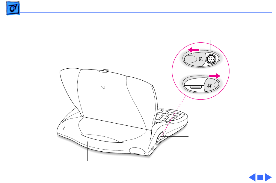
Front View
Pen Tray
Volume Control
Contrast Control
Keyboard
Speaker
Screen
Headphone
f
O
Ï
Port
Card Slot
Card Eject
Button
Pen Holder
Power Key
Page 13
Basics Rear View - 11
Rear View
Serial Cable Port
Newton
Interconnect
Port
Connection Ports
Charging
Status Light
¯
Power Adapter Port
Sliding Cover
Carrying Handle
Infrared Window
Page 14

Basics Bottom View - 12
Bottom View
Battery
Access
Cover
Reset Button
Identification
Card Holder
Page 15
Basics Keyboard - 13
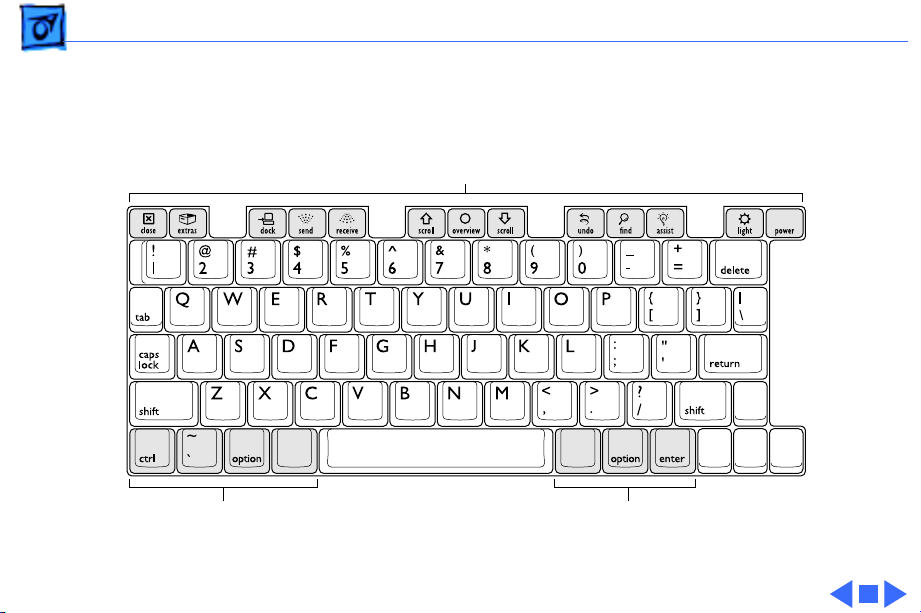
Keyboard
Special Keys
I
Ò
xx
k
¬
k
Modifier KeysModifier Keys
Page 16

K
Service Source
Specifications
eMate
Page 17

Specifications Processor - 1
Processor
CPU
ARM 710a processor running at 27 MHz
Page 18

Specifications Memory - 2
Memory
RAM
ROM
512K DRAM installed on the logic board
512K or 1 MB Flash installed on the logic board
Memory expansion connector allows addition of daughter card
containing DRAM and FLASH.
8 MB
Expandable to 16 MB ROM and 16 MB Flash on ROM daughter card.
Page 19

Specifications Controls - 3
Controls
Switches
Wake/sleep switch lid activated; wake key on keyboard
Backlight on/off switch on keyboard
Reset switch on back of unit
Page 20

Specifications I/O Interfaces - 4
I/O Interfaces
Serial
Sound
PC Card Slot
GeoPort/LocalTalk port. Uses DIN9 interface connector. Software
switching to Newton Interconnect.
External headphone jack (plugged-in headphones disable internal
speaker)
One slot
PCMCIA type I/II/III
Ejection button
Page 21

Specifications I/O Interfaces - 5
I/O Interfaces
Infrared
Power Adapter
Point-to-point short range IR
115 kbps maximum data rate
1 m maximum range
Power adapter port
Page 22

Specifications I/O Devices - 6
I/O Devices
Keyboard
Speaker
Tablet
Built-in keyboard
One internal speaker
Non-glare finish
Page 23

Specifications Video - 7
Video
Video Display
Backlight
Black and white liquid crystal display
480 x 320 pixels
0.30 mm (85 dpi) dot pitch
16 levels of gray
Optimized for landscape orientation
Electro-luminescent backlight
Yellow-green color
Intended for momentary use in low-light conditions
Page 24

Specifications Electrical - 8
Electrical
Main Battery Pack
Four AA nickel-metal-hydride (NiMH) batteries
Up to 24 hours of use before recharging
Storage capacity: 5.76 W
Fast-charge time: 1 hr.
Recharge life: 500 cycles
LED charging status
Off when AC adapter not attached
Amber while AC adapter attached and charging
Green with AC adapter attached and charged
Page 25

Specifications Physical - 9
Physical
Dimensions
Length
Width
Depth
Weight
289.6 mm
305.0 mm
53.3 mm
4.2 lb. (1.9 kg)
Page 26

Specifications Environmental - 10
Environmental
Temperature
Operating
Storage
Relative Humidity
Operating Altitude
32° to 104° F (0° to 40° C)
-13° to 140° F (-25° to 60° C)
5% to 95% noncondensing
0 to 10,000 ft. (0 to 3,048 m)
Page 27

K
Service Source
Troubleshooting
eMate
Page 28

Troubleshooting General - 1
General
The Symptom Charts included in this chapter will help you
diagnose specific symptoms related to your product. Because cures
are listed on the charts in the order of most likely solution, try
the first cure first. Verify whether or not the product continues to
exhibit the symptom. If the symptom persists, try the next cure.
(Note: If you have replaced a module, reinstall the original module
before you proceed to the next cure.)
If you are not sure what the problem is, or if the Symptom Charts
do not resolve the problem, refer to the Flowchart for the product
family.
For additional assistance, contact Apple Technical Support.
Page 29

Troubleshooting Symptom Charts/Startup - 2
Symptom Charts
Startup
Backlight blinking
after starting up
1 Power up memory test failed. If expansion memory card
installed, remove it and press reset button.
2 Remove battery, wait 30 seconds, reinstall battery, turn on
computer.
3 Remove battery, remove and reseat ROM card, reinstall
battery, turn on computer.
4 Replace logic board.
Page 30

Troubleshooting Symptom Charts/Startup - 3
Startup
eMate computer
won’t power on
1 Check LCD contrast and volume control and adjust to mid-
range.
2 Plug in AC adapter, and press reset button. Wait at least 30
seconds for boot up chime.
3 Remove adapter and battery; remove and reseat ROM card;
reinstall battery; repeat step 2.
4 If expansion memory card installed, remove card and repeat
step 2.
5 If boot up chime is heard and no image on screen, press
backlight key. If light comes on, replace LCD.
6 Replace logic board.
Page 31

Troubleshooting Symptom Charts/System - 4
System
Error message
displayed: “Your
eMate is missing
important
calibration
information and
should be returned to
a service provider.”
1 Replace logic board.
2 Send logic board to repair center.
Page 32

Troubleshooting Symptom Charts/Audio - 5
Audio
Speaker doesn’t work 1 Remove anything plugged into the headphone jack.
2 Check volume level using front slider control.
3 Perform a soft reset (refer to “Resetting the eMate” in the
Basics chapter). Wait; listen for startup chime.
4 Remove battery, wait 30 seconds, reinsert battery, turn on
computer.
5 Replace speaker.
6 Replace logic board.
Page 33

Troubleshooting Symptom Charts/PC Card Module (PCMCIA) - 6
PC Card Module (PCMCIA)
PCMCIA doesn’t work 1 Remove and reseat PC card.
2 Perform a soft reset (refer to “Resetting the eMate” in the
Basics chapter).
3 Remove battery, wait 30 seconds, reinsert battery, turn on
computer.
4 Replace logic board.
Page 34

Troubleshooting Symptom Charts/Infrared Communication - 7
Infrared Communication
IR doesn’t work 1 Perform a soft reset (refer to “Resetting the eMate” in the
Basics chapter).
2 Remove battery, wait 30 seconds, reinsert battery, turn on
computer.
3 Replace logic board.
Page 35

Troubleshooting Symptom Charts/Keyboard - 8
Keyboard
Keyboard doesn’t
work
1 Perform a soft reset (refer to “Resetting the eMate” in the
Basics chapter).
2 Freeze packages (refer to “Freezing Software Packages” in
the Basics chapter).
3 Perform a hard reset (refer to “Resetting the eMate” in the
Basics chapter).
4 Run keyboard diagnostics (optional).
5 Replace keyboard.
6 Replace logic board.
Page 36

Troubleshooting Symptom Charts/Tablet - 9
Tablet
Tablet doesn’t work 1 Verify correct application (for example, Notes) is being
used.
2 Perform a soft reset (refer to “Resetting the eMate” in the
Basics chapter).
3 Freeze packages (refer to “Freezing Software Packages” in
the Basics chapter).
4 Remove battery, wait 30 seconds, reinsert battery, turn on
computer.
5 Perform a hard reset (refer to “Resetting the eMate” in the
Basics chapter).
6 Run diagnostic tablet test (optional).
7 Reseat display/tablet flex cable on logic board and LCD sides.
8 Remove tablet, reseat tablet flex connector.
9 Replace tablet.
10 Replace logic board.
Page 37

Troubleshooting Symptom Charts/Backlight - 10
Backlight
Backlight doesn’t
work
Note:
The backlit screen can be difficult to see in a well-lit
environment. Verify backlight operation in a dimly lit room.
1 Perform a soft reset (refer to “Resetting the eMate” in the
Basics chapter).
2 Remove battery, wait 30 seconds, reinsert battery, turn on
computer.
3 Replace backlight.
4 Replace logic board.
Page 38

Troubleshooting Symptom Charts/Battery - 11
Battery
Battery won’t charge 1 Perform a soft reset (refer to “Resetting the eMate” in the
Basics chapter).
2 Remove and test battery.
3 Reinstall battery and let unit charge.
Note:
Although it can be used, a Newton 7-watt AC power adapter
will charge the unit slower than a Newton 9-watt AC power
adapter. Check the Technical Information Library for more
information.
4 Run diagnostic battery test (optional).
5 If the eMate displays an error message that says the battery
will not accept a charge, repeat steps 1 through 4.
Important:
period can require four to five iterations of these steps
before it is fully charged. If after five iterations the eMate
still fails to charge, go to step 6.
A battery that has been idle in an eMate for a long
Page 39

Troubleshooting Symptom Charts/Battery - 12
6 Replace battery.
7 Replace logic board.
Page 40

Troubleshooting Symptom Charts/Serial Port - 13
Serial Port
Serial port doesn’t
work
1 Test with Newton Interconnect Adapter.
2 Perform a soft reset (refer to “Resetting the eMate” in the
Basics chapter).
3 Freeze packages (refer to “Freezing Software Packages” in
the Basics chapter).
4 Remove battery, wait 30 seconds, reinsert battery, power
on computer.
5 If 9-pin connector works, but 26-pin connector doesn’t
work, replace Newton Interconnect Adapter.
6 If 26-pin connector works, but 9-pin connector doesn't
work, replace logic board.
7 Replace logic board.
Page 41

Troubleshooting eMate Service Diagnostics/Serial Port - 14
eMate Service Diagnostics
The optional service diagnostic software comes on a PC card
(Apple part number 077-0153); it is designed to isolate the
symptom to a replaceable module. Replaceable modules include:
• Logic board (included with Top Case Assembly, 661-1194).
• RAM and ROM expansion cards
• Display (Assembly)
• Keyboard
• Battery
Important:
cannot be identified using standard troubleshooting steps from the
Symptom Charts in this chapter.
Use the diagnostic PC card when the symptom’s cause
Page 42

Troubleshooting eMate Service Diagnostics/Serial Port - 15
To begin the service diagnostic routines, open the eMate lid to turn
on the power and insert the diagnostic PC card. You’ll see a dialog
box that you should ignore. Press the Reset button until you hear a
beep. Immediately remove the diagnostic PC card. Follow
instructions on the screen to tap the center of a small box.
Reset Button
Page 43

Troubleshooting eMate Service Diagnostics/Serial Port - 16
You’ll see the Service Menu:
SERVICE MENU
EXIT
LOGIC BOARD TST
EX RAM CARD TST
ROM CARD TEST
LCD UNIT TEST
KEYBOARD TEST
BATTERY TEST
LOOP TEST
Page 44

Troubleshooting eMate Service Diagnostics/Logic Board Test - 17
Logic Board Test
When you tap the Logic Board Test box, you’ll see these choices:
NON
DESTRUCTIVE
Caution:
section, but erases all existing data.
Tapping Non Destructive or Destructive will start the test
routine, and you’ll see messages flash on the screen telling what
test is in progress.
Choosing the Destructive box allows testing the storage
DESTRUCTIVE
WILL ERASE DATA
PERMANENTLY
ABORT
Page 45

Troubleshooting eMate Service Diagnostics/Logic Board Test - 18
When you see this message:
CLOSE AND OPEN LID WITHIN 20 SEC
quickly close and open the eMate lid.
The next message that requires you to take action looks like this:
PUSH & RELEASE PCMCIA SWITCH WITHIN 20 S
Page 46

Troubleshooting eMate Service Diagnostics/Logic Board Test - 19
Push the card eject button on the right side of the eMate. This
ejects any PC card present in the slot. (There should be no PC card
present, but if there was, do not reinsert it.)
O
Ï
f
Card Slot
Card Eject
Button
Page 47

Troubleshooting eMate Service Diagnostics/Logic Board Test - 20
The volume slider test displays this on the screen:
MOVE VOLUME SLIDER AND CHECK IF VOLUME SLIDER
INDICATOR ON SCREEN MOVES. TAP SCREEN TO EXIT.
Cursor
Page 48

Troubleshooting eMate Service Diagnostics/Logic Board Test - 21
Move the volume slider and watch to see that the cursor moves
from one end to the other end of the line displayed on the screen.
Tap the screen to leave the volume slider test, and you’ll see these
boxes on the screen:
OK
NG
Tap OK if the volume slider test passed, or tap NG (No Good) if the
test failed. If you tap OK, you’ll see another series of automated
test messages flash on the screen. You’ll hear a series of beeps
during the speaker test.
Page 49

Troubleshooting eMate Service Diagnostics/Logic Board Test - 22
When a message indicates that the headphone test is in progress,
plug in a headphone set to hear the test.
Headphone
f
O
Ï
Port
Page 50

Troubleshooting eMate Service Diagnostics/Logic Board Test - 23
If all tests passed, you’ll see this message:
LOGIC BOARD TEST PASSED — TAP SCREEN
Now tap the screen to return to the Service Menu.
Page 51

Troubleshooting eMate Service Diagnostics/RAM Card Test - 24
RAM Card Test
When you tap the Ex RAM Card Test box, you’ll see these choices:
NON
DESTRUCTIVE
Caution:
section, but erases all existing data.
Tapping Non Destructive or Destructive will start the test
routine, and you’ll see messages flash on the screen telling what
test is in progress.
If no RAM card has been installed, you’ll see the test failed
message.
Choosing the Destructive box allows testing the storage
DESTRUCTIVE
WILL ERASE DATA
PERMANENTLY
ABORT
Page 52

Troubleshooting eMate Service Diagnostics/ROM Card Test - 25
ROM Card Test
Tap the ROM Card Test box to initiate automatic testing. There is
no interaction required for this test.
Page 53

Troubleshooting eMate Service Diagnostics/LCD Unit Test - 26
LCD Unit Test
When you tap the LCD Unit Test box on the Service Menu, you’ll
get the message:
TAP SCREEN FOR EACH PATTERN
Each time you tap the screen, a new screen pattern fills the
display. The first four patterns have very subtle changes, and may
be barely perceptible. Be sure to do this test where the lighting is
optimum for viewing the eMate display. You’ll tap the screen a
total of seven times before getting the OK and NG boxes at the
bottom of the screen.
Page 54

Troubleshooting eMate Service Diagnostics/LCD Unit Test - 27
If you tap the OK box, the tablet test starts. Follow the
instructions in the next message.
TABLET TEST — TAP AND DRAG PEN ON SCREEN.
WHEN PEN IS NOT MOVING CHECK IF IT IS IN BOX.
UPON TEST COMPLETION HIT ANY KEY TO EXIT.
A small box should follow your pen as you drag the pen on the
screen. If you hold the pen still in one spot on the screen, the point
of the pen should rest within the box. Press any key to exit. If the
tablet test passed, tap the OK box when the OK and NG boxes appear
at the bottom of the screen. This will cause the backlight to come
on, and you’ll see this message:
TAP SCREEN TO TURN OFF
Page 55

Troubleshooting eMate Service Diagnostics/LCD Unit Test - 28
Tap the screen to see the next message:
LCD UNIT TEST PASSED — TAP SCREEN
Tap the screen to return to the Service Menu.
Page 56

Troubleshooting eMate Service Diagnostics/Keyboard Test - 29
Keyboard Test
Tap the Keyboard Test box on the Service Menu. You’ll see this
message:
WAITING FOR CLOSEBOX
The Closebox key is found in the upper left corner of the keyboard.
You can press each key when it’s requested, but a much faster way
to test all the keys is to run your finger over the keys from left to
right, top to bottom. If you don’t press a key within 10 seconds,
you’ll see a message saying the test failed.
Page 57

Troubleshooting eMate Service Diagnostics/Keyboard Test - 30
To start, place a finger on the Closebox key, and drag across all
keys in the top row so that each key is briefly pressed down.
Continue this process for each row, moving down one row at a time
and always starting from the extreme left side. When all six rows
of keys have been pressed, you’ll get the pass or fail message. Tap
the screen to return to the Service Menu.
Page 58

Troubleshooting eMate Service Diagnostics/Battery Test - 31
Battery Test
The battery test only works if a battery is installed and the eMate
power adapter is plugged in.
Charging
Status Light
¯
Power Adapter Port
Page 59

Troubleshooting eMate Service Diagnostics/Battery Test - 32
Tap the Battery Test box to see this message:
BATTERY CHARGE TEST — OK IF LED IS AMBER
In a few seconds, the message disappears and you’ll see the OK and
NG boxes. Look at the charging status light on the back of the
eMate. If the light is amber, the battery test passed and you should
tap the OK box. If the light is not amber, the battery would not
charge, the battery test failed, and you should tap the NG box.
Page 60

Troubleshooting eMate Service Diagnostics/Loop Test - 33
Loop Test
The loop test runs all automatic tests and ignores all tests
requiring interaction. Tap the Loop Test box on the Service Menu.
You’ll see these choices:
NON
DESTRUCTIVE
Caution:
section, but erases all existing data.
Tapping Non-Destructive or Destructive displays the Loop Test
Menu.
Choosing the Destructive box allows testing the storage
DESTRUCTIVE
WILL ERASE DATA
PERMANENTLY
ABORT
Page 61

Troubleshooting eMate Service Diagnostics/Loop Test - 34
Here’s the default Loop Test Menu:
EXIT RUN
TIME
ELPSE
LOOPS
COUNT
OK
NG
00:00:00:00
00:00:00:00
0
0
0
0
LOGIC BOARD
RAM CARD TEST
ROM CARD TEST
X
If you tap the Run box when the default screen is displayed, the
logic board test will run once.
Page 62

Troubleshooting eMate Service Diagnostics/Loop Test - 35
Set Loop Test Time
To set an amount of time for the test(s) to run, tap inside the box
to the right of TIME to see the Numeric Entry Menu:
Days
Cancel
Entry
Hours
00:00:00:00
1
4
7
DEL QUIT ENT
Return to Loop Test Menu
2
5
8
0
Minutes
3
6
9
Seconds
Enter
Time
Page 63

Troubleshooting eMate Service Diagnostics/Loop Test - 36
The time displayed in the top box of the Numeric Entry Menu
indicates Days:Hours:Minutes:Seconds. For an example, tap the
number 2 three times. Two minutes and 22 seconds appear in the
top box.
00:00:02:22
1
4
7
DEL QUIT ENT
2
5
8
0
3
6
9
Page 64

Troubleshooting eMate Service Diagnostics/Loop Test - 37
Tap the ENT box to enter this amount of time and see the Loop Test
Menu again.
EXIT RUN
TIME
ELPSE
LOOPS
COUNT
OK
NG
00:00:02:22
00:00:00:00
0
0
0
0
LOGIC BOARD
RAM CARD TEST
ROM CARD TEST
X
Page 65

Troubleshooting eMate Service Diagnostics/Loop Test - 38
To continue an example test, tap inside the RUN box at the top of
the screen. When the testing is complete, the Loop Test Menu
displays the results.
EXIT RUN
TIME
ELPSE
LOOPS
COUNT
OK
NG
00:00:02:22
00:00:02:23
0
6
6
0
LOGIC BOARD
RAM CARD TEST
ROM CARD TEST
OK
Page 66

Troubleshooting eMate Service Diagnostics/Loop Test - 39
The result shown to the right of COUNT is the number of loops
completed. The result to the right of OK is the number of tests
passed. The result to the right of NG is the number of tests failed.
Page 67

Troubleshooting eMate Service Diagnostics/Loop Test - 40
Set Loop Number
Now, enter the number of loops to execute for all three tests on the
Loop Test Menu. Tap inside the boxes to the right of RAM and ROM,
and then tap in the number box to the right of LOOPS.
EXIT RUN
TIME
ELPSE
LOOPS
COUNT
OK
NG
00:00:00:00
00:00:00:00
0
0
0
0
LOGIC BOARD
RAM CARD TEST
ROM CARD TEST
X
X
X
Page 68

Troubleshooting eMate Service Diagnostics/Loop Test - 41
In the Numeric Entry Menu, tap the number 6 and then tap inside
the ENT box.
1
4
7
DEL QUIT ENT
2
5
8
0
3
6
9
Page 69

Troubleshooting eMate Service Diagnostics/Loop Test - 42
Back in the Loop Test Menu, tap inside the RUN box.
EXIT RUN
TIME
ELPSE
LOOPS
COUNT
OK
NG
00:00:00:00
00:00:00:00
6
0
0
0
LOGIC BOARD
RAM CARD TEST
ROM CARD TEST
X
X
X
Page 70

Troubleshooting eMate Service Diagnostics/Loop Test - 43
Here’s an example of what the Loop Test Menu in result mode
might look like after running six loops.
EXIT RUN
TIME
ELPSE
LOOPS
COUNT
OK
NG
00:00:00:00
00:00:02:44
6
6
12
6
LOGIC BOARD
RAM CARD TEST
ROM CARD TEST
OK
NG
OK
Page 71

Troubleshooting eMate Service Diagnostics/Loop Test - 44
Interrupting the Loop Cycle
At the beginning of each loop test cycle, the Loop Test Menu is
briefly displayed. At the top of the Loop Test Menu there are two
buttons marked EXIT and RUN. To interrupt the looping cycle, tap
EXIT. A STOP and CONTINUE button appear at the bottom of the
screen. Tap STOP to end the loop test completely. Tap CONTINUE to
cancel the interruption and resume the loop test.
Note:
If you want another loop test after tapping STOP, tap RUN to
reset all test results. Enter a new time or number of loops.
Page 72

Troubleshooting eMate Service Diagnostics/Test Result Messages - 45
Test Result Messages
Here’s a table of possible messages displayed at the end of tests.
Test Name Error Message Pass Message
Logic Board Logic Board Test Failed! Logic Board Test Passed - Tap Screen.
RAM Card Expansion RAM Card
Test Failed!
ROM Card Expansion ROM Card
Test Failed!
LCD Unit LCD Unit Test Failed! LCD Unit Test Passed - Tap Screen.
Keyboard Keyboard Test Failed! Keyboard Test Passed - Tap Screen.
Battery Battery Test Failed! Battery Test Passed - Tap Screen.
After one of these messages appears in the middle of the screen,
tap the screen to return to the Service Menu.
Expansion RAM Card Test
Passed - Tap Screen.
Expansion ROM Card Test
Passed - Tap Screen
Page 73

Troubleshooting eMate Service Diagnostics/Quitting Service Diagnostics - 46
Quitting Service Diagnostics
Important:
slot.
To leave the Service Diagnostics program, press the Reset button,
hold the button several seconds after you hear a beep, and wait
until the diagnostic screen disappears and the eMate screen is
blank. Wait briefly for the Newton operating system to launch.
The operating system will launch twice before the eMate is ready
for normal use.
Be sure there are no PC cards inserted in the PC card
Page 74

K
Service Source
T ak e Apart
eMate
Page 75

Take Apart Access Door - 1
Access Door
Access Door
Before you begin, unplug the
power adapter and turn off
the power using the
keyboard Power key.
Caution:
components that are
susceptible to ESD damage.
To prevent damage, wear a
grounding wriststrap.
Review the ESD precautions
in Bulletins/Safety.
The eMate contains
Page 76

Take Apart Access Door - 2
1 With the display lid
closed, turn over the
eMate and use a T-8 torx
Access Door T-8 Screws
driver to remove the two
screws from the access
door.
Page 77

Take Apart Access Door - 3
2 Tilt up the access door to
remove it from the
bottom case.
Access Door
Bottom Case
Page 78

Take Apart Battery - 4
Battery
Battery
Before you begin, remove
the access door.
Caution:
components that are
susceptible to ESD damage.
To prevent damage, wear a
grounding wriststrap.
Review the ESD precautions
in Bulletins/Safety.
The eMate contains
Page 79

Take Apart Battery - 5
Bottom Case
Battery/
Battery Sleeve
J11
1 Lift up the battery and
battery sleeve from the
bottom case.
2 Disconnect battery
connector J11.
Page 80

Take Apart Battery - 6
3 Slide the battery out of
Battery Sleeve
Battery
the battery sleeve.
Page 81

Take Apart Battery - 7
J11
Replacement Note:
Reinstall the battery and
battery sleeve so that the
battery connector wires to
connector J11 are not
pinched or strained.
Page 82

Take Apart ROM Card - 8
ROM Card
Before you begin, remove
the following:
• Access door
• Battery
ROM Card
Caution:
components that are
susceptible to ESD damage.
To prevent damage, wear a
grounding wriststrap.
Review the ESD precautions
in Bulletins/Safety.
The eMate contains
Page 83

Take Apart ROM Card - 9
1 Push outward on the
metal locking clips so
the ROM card tilts up.
2 Remove the ROM card
from the bottom case.
ROM Card
Locking Clips
Page 84

Take Apart Display Assembly - 10
Display Assembly
Before you begin, remove
Display
the following:
• Access door
• Battery
• ROM card
Caution:
components that are
susceptible to ESD damage.
To prevent damage, wear a
grounding wriststrap.
Review the ESD precautions
in Bulletins/Safety.
Caution:
fragile and easily torn or
The eMate contains
eMate cables are
Page 85

Take Apart Display Assembly - 11
Screw Plugs
damaged. Handle all cables
with care.
1 Position the display so
it lies completely flat
and fully open.
2 Using a flat-blade
jeweler’s screwdriver,
pry out the four rubber
screw plugs at the
corners of the display.
Replacement Note:
Reinstall the screw
plugs so the cupped
surface covers the screw
and the smooth surface is
outside.
Page 86

Take Apart Display Assembly - 12
3 Remove the four T-8
torx screws from the
corners of the display.
T-8 Screw
Page 87

Take Apart Display Assembly - 13
4 Grasp the lower edge of
the display bezel, and
pull it up and off to
release the holding tabs.
Bezel
Page 88

Take Apart Display Assembly - 14
5 Using a Phillips #0
jeweler’s screwdriver,
remove the two screws
and washers from the top
Screw
corners of the display.
6 Disconnect the backlight
connector at the left side
of the display.
Screw
Backlight
Connector
Page 89

Take Apart Display Assembly - 15
7 At the bottom right
corner hinge, use a
Phillips #0 jeweler’s
screwdriver to remove
the bottom screw and
washer.
Screw
Page 90

Take Apart Display Assembly - 16
8 Gently tilt up the display
and rest it face-down on
Display
Keyboard
the keyboard.
Page 91

Take Apart Display Assembly - 17
9 Locate the ribbon cable
at connector LJ6.
10
Caution:
Do not use
pliers or a screwdriver
to remove the ribbon
cable: this could damage
the traces on the cable.
Move the two locking
clips forward to release
the ribbon cable.
Locking Clip
LJ6
Locking Clip
Page 92

Take Apart Display Assembly - 18
11
Caution:
Pick up the
display by its edges;
Display
avoid touching its
delicate components.
Lift the display off the
keyboard.
Page 93

Take Apart Backlight - 19
Backlight
Backlight
Before you begin, remove
the following:
• Access door
• Battery
• ROM card
• Display
Caution:
components that are
susceptible to ESD damage.
To prevent damage, wear a
grounding wriststrap.
Review the ESD precautions
in Bulletins/Safety.
The eMate contains
Page 94

Take Apart Backlight - 20
1 Press the tab on the
display assembly to
Backlight
Tab
Display
access the edge of the
backlight.
Page 95

Take Apart Backlight - 21
2 Using your fingers or a
Backlight
needlenose pliers, grasp
the backlight’s clear
plastic edge and slide the
backlight out of the
display assembly.
Display
Page 96

Take Apart Backlight - 22
Backlight
Caution:
Be careful not
to bend or damage the
backlight.
Page 97

Take Apart Top Cover - 23
Top Cover
Top Cover
Before you begin, remove
the following:
• Access door
• Battery
• ROM card
• Display
Caution:
components that are
susceptible to ESD damage.
To prevent damage, wear a
grounding wriststrap.
Review the ESD precautions
in Bulletins/Safety.
The eMate contains
Page 98

Take Apart Top Cover - 24
(~90 Degrees)
Caution:
eMate cables are
fragile and easily torn or
damaged. Handle all cables
with care.
1 Position the top cover so
it is open and positioned
at an angle of about 90110 degrees to the
keyboard.
Caution:
Do not lower
the cover to less than 90
degrees during this
procedure or the lid
switch could be damaged.
Page 99

Take Apart Top Cover - 25
2 Route the backlight
connector wires out of
the routing channels.
Backlight
Wires
Routing
Channel
Routing
Channel
Page 100

Take Apart Top Cover - 26
Hinge
Screws
Top Cover
Top Case
Screw
3 Using a Phillips #0
jeweler’s screwdriver,
remove the three
screws at the bottom
hinges.
4 Without moving the
hinges, separate the top
cover from the top case.
Hinge
 Loading...