

Page 1

K
Service Source
Color StyleWriter Pro
Page 2
K
Service Source
Basics
Color StyleWriter Pro
Page 3
Basics Overview - 1
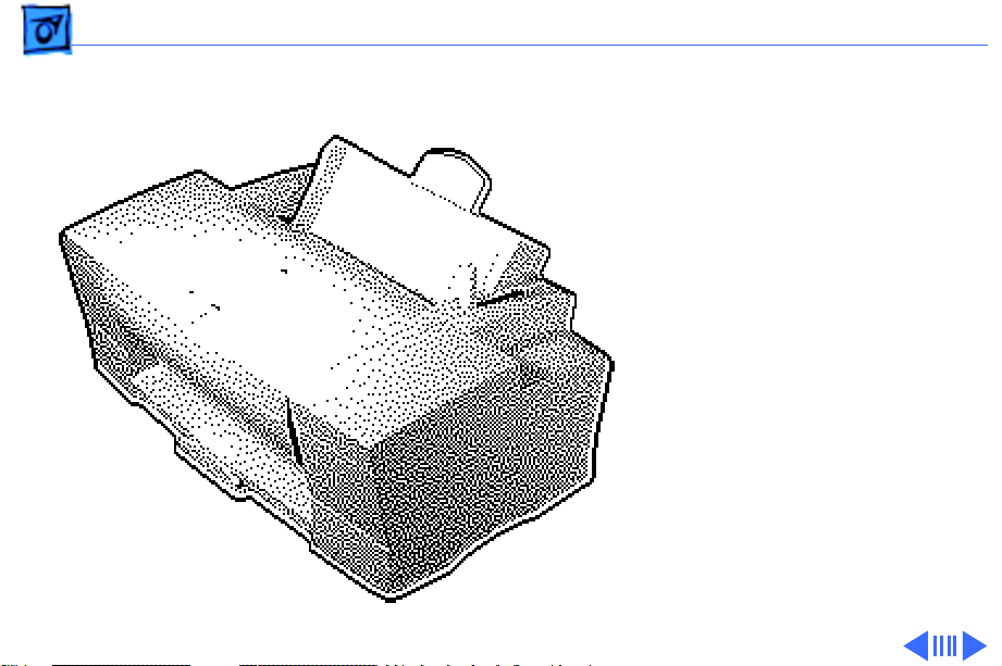
Overview
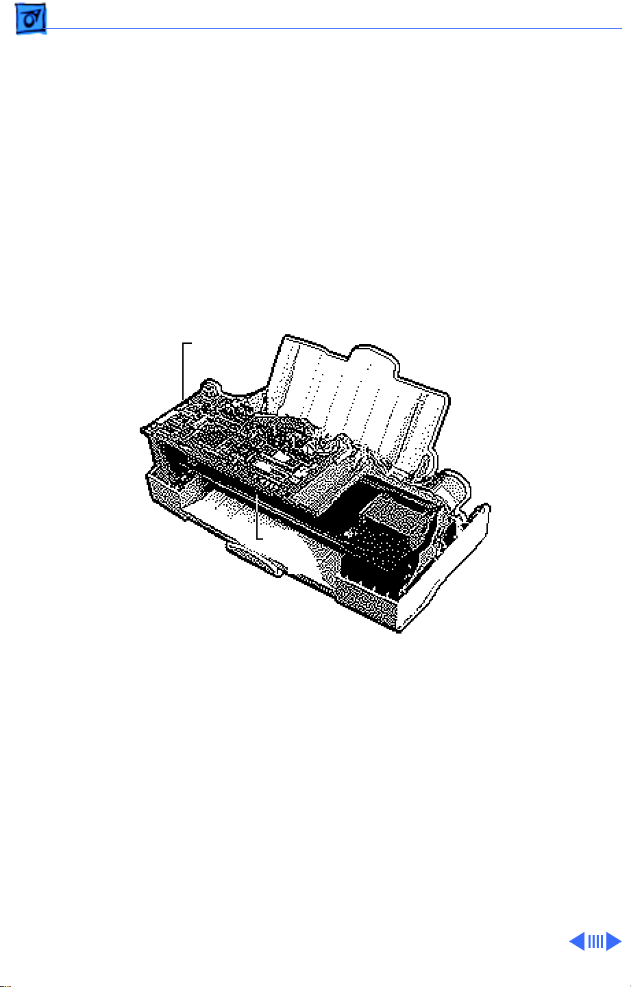
The Color StyleWriter Pro
is a desktop color bubblejet printer for personal use.
It has various features such
as high-speed printing, high
print quality, printing on
plain paper, and a cut sheet
feeder.
The user can easily replace
the print head (64 nozzles,
four colors) and ink
cartridges (each color has a
separate cartridge).
Page 4

Basics Overview - 2
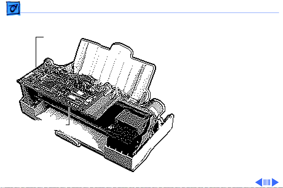
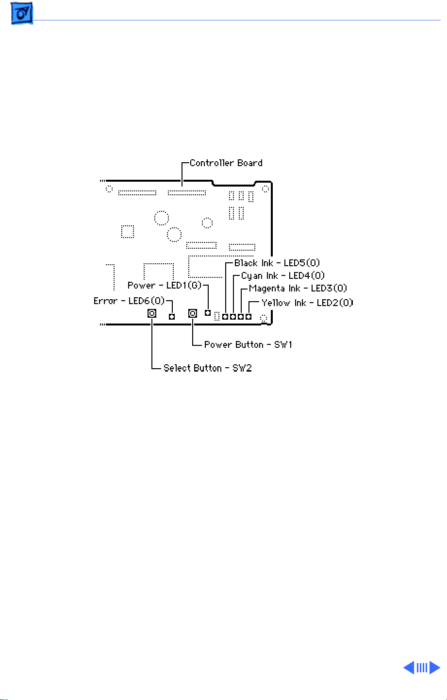
The Color StyleWriter Pro
has six LEDs on the
Controller
Board
controller board which can
aid in troubleshooting the
printer. See the
Troubleshooting chapter for
more information.
LEDs
Page 5
Basics Service Mode - 3
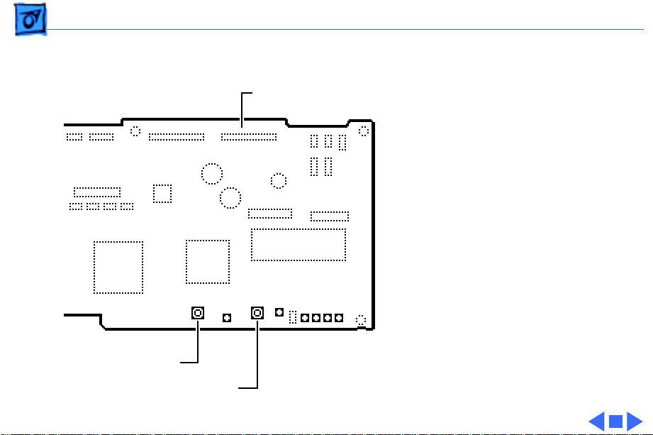
Service Mode
Controller
Board
Buttons and LEDs
Note:
This procedure uses
the buttons and LEDs on the
controller board to perform
service functions, i.e., test
pages.
Note:
You must remove the
top cover and the inner
cover to access the
controller board. See
“Covers” in the Take Apart
chapter.
Page 6
Basics Service Mode - 4
Hold down the power and
select buttons and plug in
Controller Board
the printer power cord.
Note:
The printer will emit
a four-tone beep indicating
that it is in the service
mode.
See the “Color StyleWriter
Pro Utility” and
“Alignment” in the
Adjustments chapter for
additional information.
Select Button
Power Button
Page 7
Basics Service Test Page - 5
Service Test Page
Note:
This procedure
explains how to print the
service test page, which
indicates if the print heads
need to be aligned. You must
be in service mode to print a
service test page.
1 Place paper in the cut
sheet feeder.
2 Place printer in service
mode. See “Service
Mode” in this chapter.
Print Heads
Page 8
Basics Service Test Page - 6
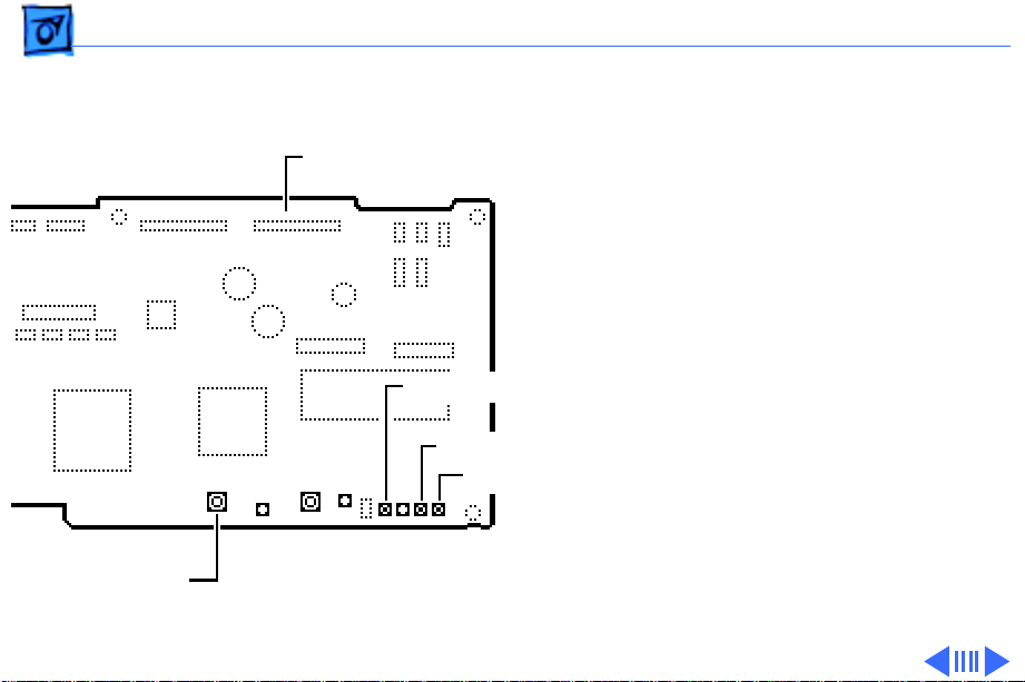
3 Press the select button
until the black (LED 5),
Controller Board
magenta (LED 3), and
yellow (LED 2) LEDs
light up.
Black LED (LED 5)
Magenta LED (LED 3)
Yellow LED (LED 2)
Select Button
Page 9
Basics Service Test Page - 7
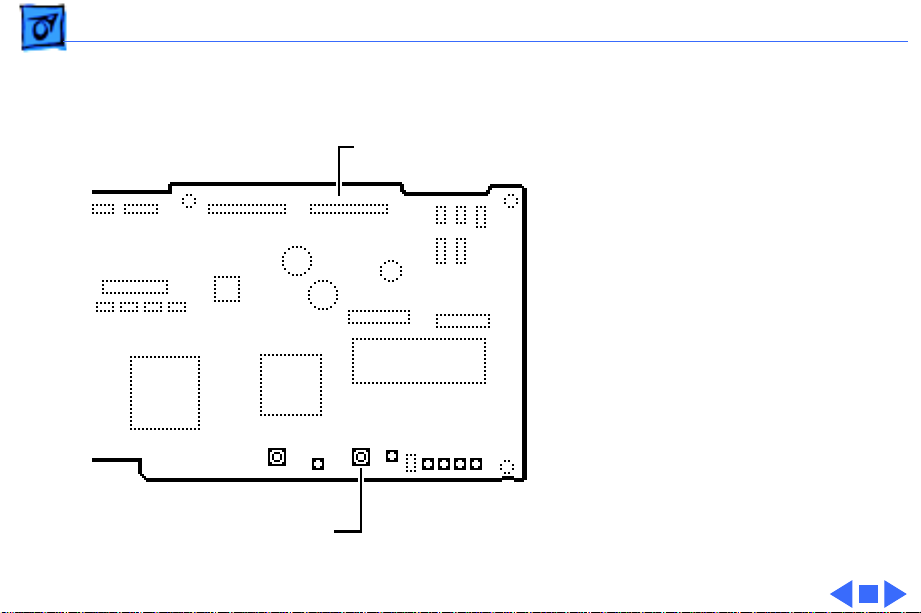
4 Press the power button.
Note:
Controller Board
Power Button
The printer will now
print the test page.
Page 10
K
Service Source
Specifications
Color StyleWriter Pro
Page 11

Specifications Characteristics - 1
Characteristics
Print Methods
Throughput
Print Head
Print Head Life
Input Buffer
Serial bubble jet ink-on-demand
170 cps (10 cpi) text/standard speed mode
240 cps (10 cpi) text/high speed mode
1 x 64 nozzles for each color
Thousands of pages
60 KB
Page 12

Specifications Graphics - 2
Graphics
Resolution
360 dpi (best mode)
180 dpi (draft mode)
Page 13

Specifications Paper Handling - 3
Paper Handling
Paper
Cut Sheets
Envelopes
Plain paper, coated (recommended for color picture output)
LTR, LGL, A4
U.S. Letter (LTR): 8.5 x 11 in. (215.9 mm x 279.4 mm)
U.S. Legal (LGL) : 8.5 x 14 in. (215.9 mm x 355.6 mm)
A4: 210 mm x 297 mm
Weight: 16–24 lbs. Capacity: 100 sheets (A4, LTR)
Commercial number 10, monarch, and other sizes
Capacity: 15 envelopes
Page 14

Specifications Paper Handling - 4
Transparencies
Back-Print Film
Coated transparencies, most ink jet transparencies
Letter, A4
For superior graphics and imaging results, premium paper and
back-print film are recommended
Page 15

Specifications Ink Cartridges - 5
Ink Cartridges
Type
Ink Color
Ink Amount
Shelf Life
Cartridge Life
Color ink cartridges (four available)
Black, cyan, magenta, yellow
Approx. 8 g (per cartridge)
6 months (installed in printer)
18 months (in original package)
Text: Approx. 315 pages (A4/LTR) at 5% coverage per color
Page 16

Specifications Environmental - 6
Environmental
Acoustic Noise Level
Temperature
Humidity
Approx. 45 dB (reference level)
59–86°F (15–30°C)
10–80% (no condensation)
Page 17

Specifications Electrical - 7
Electrical
Electrical Requirements
Power Consumption
120 V, 60 Hz, 1 amp
220–240 V, 50 Hz, 0.5 amp
28 W maximum
Page 18

Specifications Physical - 8
Physical
Dimensions
Weight
Height: 7.2 in. (184 mm)
Width: 16.5 in. (418 mm)
Depth: 10.1 in. (256 mm)
Approx. 11 lbs. (5 kg)
Page 19

K
Service Source
Troubleshooting
Color StyleWriter Pro
Page 20

Troubleshooting General/ - 1
General
The Symptom Charts included in this chapter will help you
diagnose specific symptoms related to your product. Because cures
are listed on the charts in the order of most likely solution, try
the first cure first. Verify whether or not the product continues to
exhibit the symptom. If the symptom persists, try the next cure.
(Note: If you have replaced a module, reinstall the original module
before you proceed to the next cure.)
If you are not sure what the problem is, or if the Symptom Charts
do not resolve the problem, refer to the Flowchart for the product
family.
For additional assistance, contact Apple Technical Support.
Page 21
Troubleshooting LEDs/ - 2
LEDs
The Color StyleWriter Pro has six LEDs on the controller board
which can aid in troubleshooting the printer. The six LEDs are:
• Error LED
• Power LED
• K (black) Ink LED
• C (cyan) Ink LED
• M (magenta) Ink LED
• Y (yellow) Ink LED
Controller
Board
LEDs
Page 22
Troubleshooting LEDs/ - 3
The power button and the select button are used in service mode to
choose servicing options. Pressing the select button toggles the ink
LEDs and pressing the power button selects the appropriate
option.
See “Service Mode” in the Basics chapter for additional
information.
Page 23
Troubleshooting LEDs/ - 4
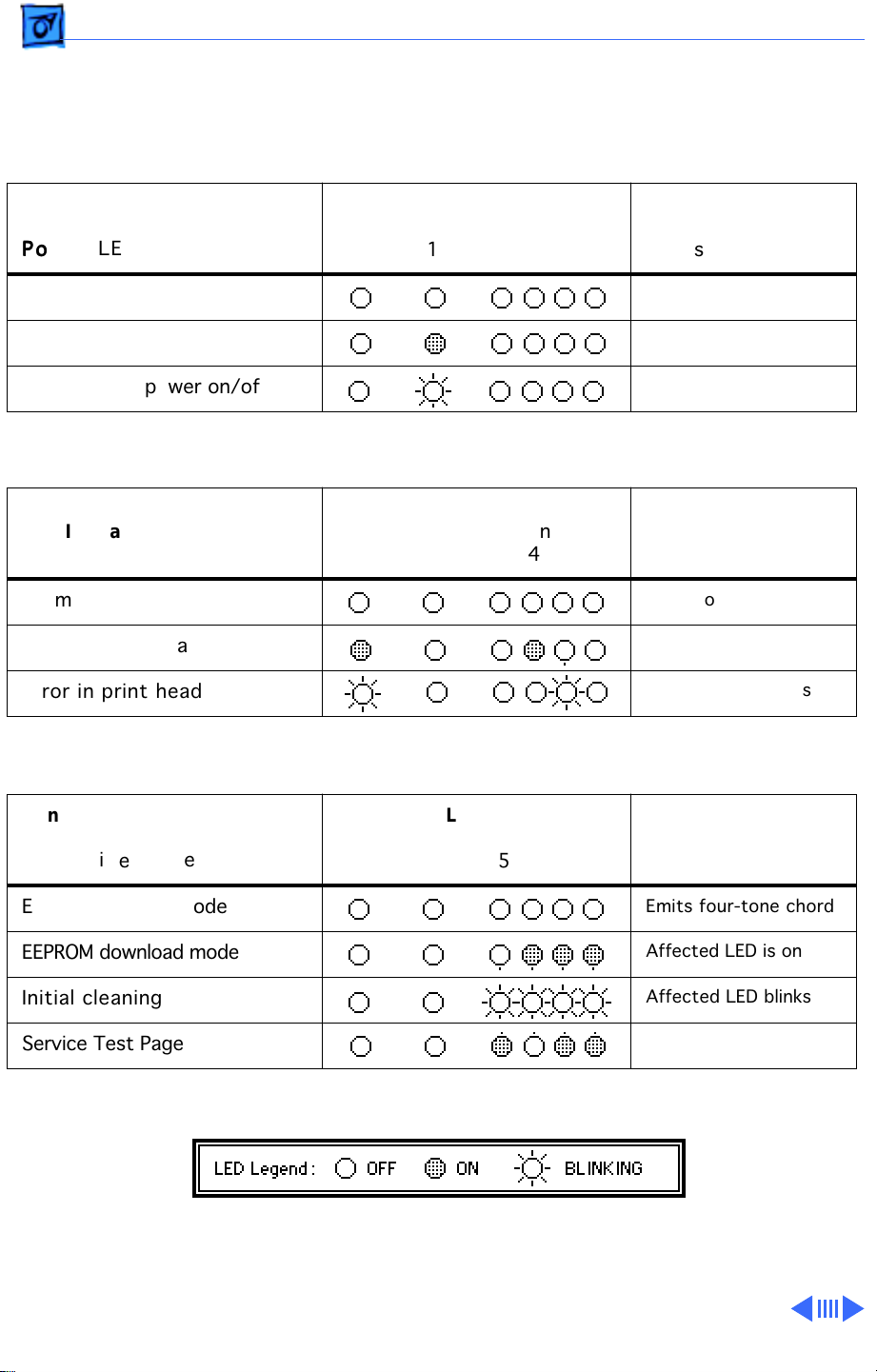
The LEDs indicate the state of the printer or whether an error has occurred (e.g., carriage
control error, paper jam).
The following charts provide a summary of printer states and error codes.
Printer State
LED Indication Summary
Power LED
Power off
Power on
Transition of power on/off
Printer State
LED Indication Summary
Ink LED
Normal condition
Error in other than print head
Error in print head
LEDs
Error Power Ink
6 1 5 4 3 2
LEDs
Error Power Ink
6 1 5 4 3 2
Notes
Notes
Power on
Affected LED is on
Affected LED blinks
Printer State
Normal LED Indication
In Service Mode
Entering service mode
EEPROM download mode
Initial cleaning
Service Test Page
LEDs
Error Power Ink
6 1 5 4 3 2
Notes
Emits four-tone chord
Affected LED is on
Affected LED blinks
Page 24
Troubleshooting LEDs/ - 5
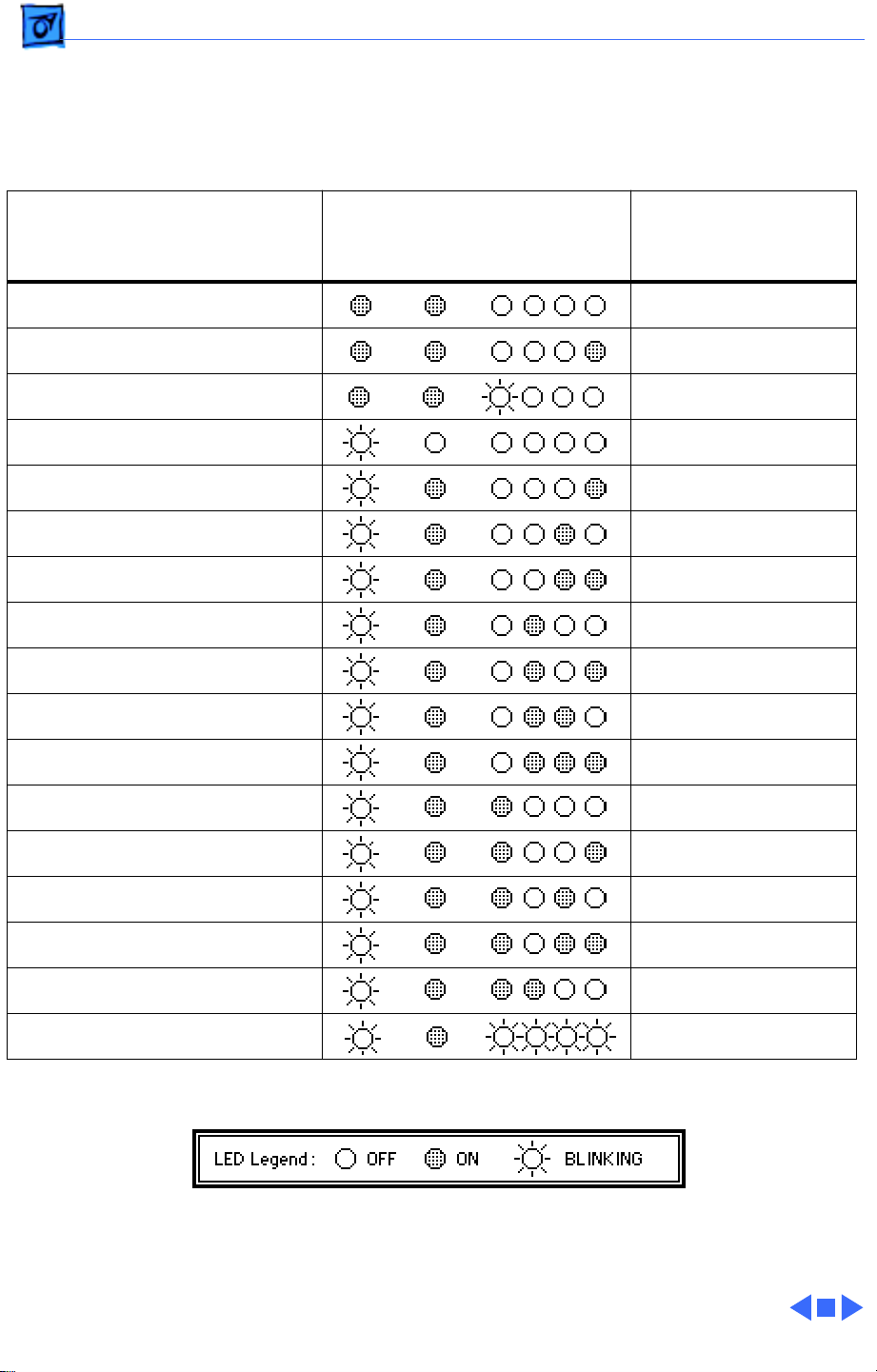
If an error is indicated, check the following chart, then go to “Error LEDs” in the Symptom
Charts.
Error Indication
Paper empty/jam
Ink absorber plate error
Ink cartridge empty
Carriage control error
Recovery error
Home position sensor error
Linear encoder error
Cleaner sensor error
Paper feed motor error
Cut sheet feeder sensor error
Thermistor error
LEDs
Error Power Ink
6 1 5 4 3 2
Notes
Empty color blinks
Carriage sensor
ROM error
RAM error
Ink absorber full error
EEPROM error
Gate array error
Print head error
Page 25

Troubleshooting Symptom Charts/Operation - 6
Symptom Charts
Operation
No power 1 Check power cable connections.
2 Replace power cord.
3 Replace fuse.
4 Replace power supply.
Does not print 1 Turn on printer and restart computer.
2 Check interface cable connections.
3 Replace printer driver.
Printer takes long
time to initialize at
first startup
Printer normally takes 5–7 minutes to prepare print head at
first startup.
Page 26

Troubleshooting Symptom Charts/Paper - 7
Paper
Paper sticks together 1 Remove excess sheets from paper tray.
2 Use specified media only.
3 Check that settings in Page Setup menu are correct.
4 Fan paper before putting in paper tray.
Paper skews 1 Remove excess sheets from paper tray.
2 Use specified media only.
3 Stack paper flush against left side of paper tray and adjust
paper guide.
4 Check rollers. Clean or replace if necessary.
Paper jams during
loading, before
printing
Carefully remove paper by hand.
Page 27

Troubleshooting Symptom Charts/Paper
(Continued)
- 8
Paper jams inside
printer
Paper jams during
output, after printing
Paper
Pull out paper in direction of paper output. (Do not pull paper
back toward you.)
Pull out paper in direction of paper output.
(Continued)
Page 28

Troubleshooting Symptom Charts/Print Quality - 9
Print Quality
Missing dots and/or
white streaks
Blurring and/or
smudging
1 Perform “Nozzle Check” and “Print Head Cleaning”. See
Additional Procedures chapter.
2 Make sure ink cartridges are set firmly.
3 Use specified media only.
4 Replace print head unit.
5 Replace carriage board. Run the Color StyleWriter Pro
Utility (see Adjustments chapter).
6 Replace controller board. Run the Color StyleWriter Pro
Utility (see Adjustments chapter).
1 Adjust print head position lever all the way down.
2 Use specified media only.
3 Make sure print head is in correct position. If necessary,
perform “Alignment”. See Adjustments chapter.
4 Perform “Print Head Cleaning.” See Additional Procedures
chapter.
Page 29

Troubleshooting Symptom Charts/Error LEDs - 10
Error LEDs
Paper jam/error 1 Pull out paper in direction of paper output.
2 Use specified media only.
3 Stack paper flush against left side of paper tray and adjust
paper guide.
4 Check rollers. Clean or replace if necessary.
5 Check for foreign objects in paper path.
6 Replace controller board. Run the Color StyleWriter Pro
Utility (see Adjustments chapter).
Ink cartridge empty 1 Replace ink cartridge.
2 Perform “Print Head Cleaning.” See Additional Procedures
chapter.
3 Perform “Print Head Purging.” See Additional Procedures
chapter
4 Replace purge unit.
5 Replace controller board. Run the Color StyleWriter Pro
Utility (see Adjustments chapter).
Page 30

Troubleshooting Symptom Charts/Error LEDs
(Continued)
- 11
Carriage control
error
Carriage home
position sensor error
Error LEDs
1 Check carriage unit path for obstructions.
2 Replace carriage motor.
3 Replace linear encoder.
4 Replace home position sensor.
5 Replace carriage ribbon cable.
6 Replace controller board. Run the Color StyleWriter Pro
Utility (see Adjustments chapter).
1 Check carriage unit path for obstructions.
2 Replace carriage motor.
3 Replace linear encoder.
4 Replace home position sensor.
5 Replace carriage ribbon cable.
6 Replace controller board. Run the Color StyleWriter Pro
Utility (see Adjustments chapter).
(Continued)
Page 31

Troubleshooting Symptom Charts/Error LEDs
(Continued)
- 12
Error LEDs
Linear encoder error 1 Make sure linear encoder is installed in correct orientation.
2 Replace linear encoder.
3 Replace controller board. Run the Color StyleWriter Pro
Utility (see Adjustments chapter).
Cleaner sensor error 1 Replace purge unit.
2 Replace carriage unit.
3 Replace controller board. Run the Color StyleWriter Pro
Utility (see Adjustments chapter).
Paper feed motor
error
Ink absorber plate
error
1 Replace paper feed motor.
2 Replace controller board. Run the Color StyleWriter Pro
Utility (see Adjustments chapter).
Replace the ink absorber plates. Run the Color StyleWriter Pro
Utility (see Adjustments chapter).
(Continued)
Page 32

Troubleshooting Symptom Charts/Error LEDs
(Continued)
- 13
Error LEDs
Cut sheet feeder
sensor error
Thermistor error 1 Replace carriage ribbon cable.
1 Check paper feed path for obstructions.
2 Check that scale holder and shaft spring at both sides of
carriage are holding carriage assembly properly. See
“Carriage Unit and Board” in Take Apart chapter.
3 Check bushing on left side of printer frame. If it is damaged
or missing, replace it. The platen and roller assembly will
not be seated properly without the bushing. See “Platen and
Roller” in Take Apart chapter.
4 Replace cut sheet feeder.
5 Replace controller board. Run the Color StyleWriter Pro
Utility (see Adjustments chapter).
2 Replace carriage board. Run the Color StyleWriter Pro
Utility (see Adjustments chapter).
(Continued)
Page 33

Troubleshooting Symptom Charts/Error LEDs
(Continued)
- 14
Error LEDs
ROM error Replace controller board. Run the Color StyleWriter Pro Utility
(see Adjustments chapter).
RAM error Replace controller board. Run the Color StyleWriter Pro Utility
(see Adjustments chapter).
EEPROM error Replace controller board. Run the Color StyleWriter Pro Utility
(see Adjustments chapter).
Gate array error Replace controller board. Run the Color StyleWriter Pro Utility
(see Adjustments chapter).
(Continued)
Page 34

Troubleshooting Symptom Charts/Error LEDs
(Continued)
- 15
Error LEDs
Print head error 1 Make sure the print head cover is fastened down securely.
2 Perform “Print Head Cleaning.” See Additional Procedures
chapter.
3 Replace print head.
4 Replace carriage ribbon cable.
5 Replace carriage board. Run the Color StyleWriter Pro
Utility (see Adjustments chapter).
Ink absorber plate
full error
Recovery error Check the paper feed clutch on the right side of the platen. Verify
Replace the ink absorber plates. Run the Color StyleWriter Pro
Utility (see Adjustments chapter).
it is in the correct position.
(Continued)
Page 35

K
Service Source
T ak e Apart
Color StyleWriter Pro
Page 36

Take Apart Covers - 1
Covers
Covers
No preliminary steps are
required before you begin
this procedure.
Note:
The Color
StyleWriter Pro has three
covers–outer, inner, and
main. This procedure
includes the removal of all
covers on the printer.
Page 37

Take Apart Covers - 2
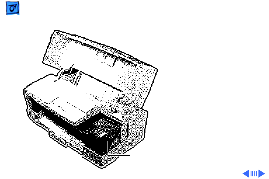
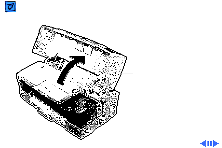
1 Raise the top cover.
Top Cover
2 Gently press in the two
hinges and lift off the top
cover.
Hinge
Hinge
Page 38

Take Apart Covers - 3
3 Release the two front
latches and remove the
inner cover.
Front
Latches
Page 39

Take Apart Covers - 4
4 Release the mounting
latches.
Page 40

Take Apart Covers - 5
5 Lay the printer on the
front side.
6 Release the rear latches
and remove the main
cover.
7 Stand the printer
upright.
Rear
Latches
Page 41

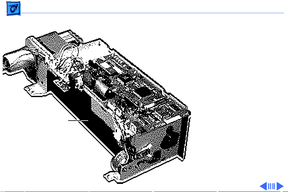
Take Apart Print Head Unit - 6
Print Head Unit
No preliminary steps are
required before you begin
this procedure.
Print Head Unit
Caution:
precautions in Bulletins/
Safety.
Caution:
printer’s ink on your hands
or clothes. Although the ink
is water soluble, it contains
dyes that will stain.
Review the ESD
Do not get the
Page 42

Take Apart Print Head Unit - 7
Print Head Unit
Caution:
To prevent the
print nozzles from clogging,
do not touch or wipe them
when removing the print
head.
Caution:
Do not leave the
print heads uncapped for
more than 12 hours or they
will dry out.
Page 43
Take Apart Print Head Unit - 8
1 Open the top cover.
Top
Cover
Page 44

Take Apart Print Head Unit - 9
2
Note:
After removing the
Ink Cartridges
ink cartridges from the
printer, place each ink
cartridge on a piece of
paper. Keep them in the
order removed; it will
make replacement
easier.
Grasp the top edge and
gently lift up and pull
out the ink cartridge.
3 Repeat for each of the
three remaining
cartridges.
Page 45

Take Apart Print Head Unit - 10
4
Ink Cartridges
Replacement Note:
not shake the ink
Do
cartridges or the ink
may leak.
Page 46

Take Apart Print Head Unit - 11
5 Push in both latches and
open the print head
Print Head Cover
cover.
Replacement Note:
When closing the print
head cover, press firmly
until you hear two clicks
and the cover will not go
down further. The cover
should be completely
horizontal. Failure to
close the print head
cover properly will
cause print head failure.
Page 47

Take Apart Print Head Unit - 12
6
Note:
To prevent the
print nozzles from
clogging, do not touch or
wipe them.
Grasp the print head and
gently remove it from
the printer.
7 Place the print head on a
piece of paper.
Print Head
Replacement Note:
Before installing a new
print head, remove the
tape that covers the
print nozzles.
Print Nozzles
Page 48

Take Apart Controller Board - 13
Controller Board
Before you begin, remove
Controller
Board
the covers.
Caution:
precautions in Bulletins/
Safety.
Note:
controller board, it is
necessary to run the Color
StyleWriter Pro Utility. See
“Color StyleWriter Pro
Utility” in the Adjustments
chapter.
Review the ESD
After replacing the
Page 49

Take Apart Controller Board - 14
1 Disconnect the following
connectors from the
controller board:
• LFM1
• JPOW1
• JCRM1
• JHPS1
• JPGS1
• JPGM1
• JAFS1
Page 50
Take Apart Controller Board - 15
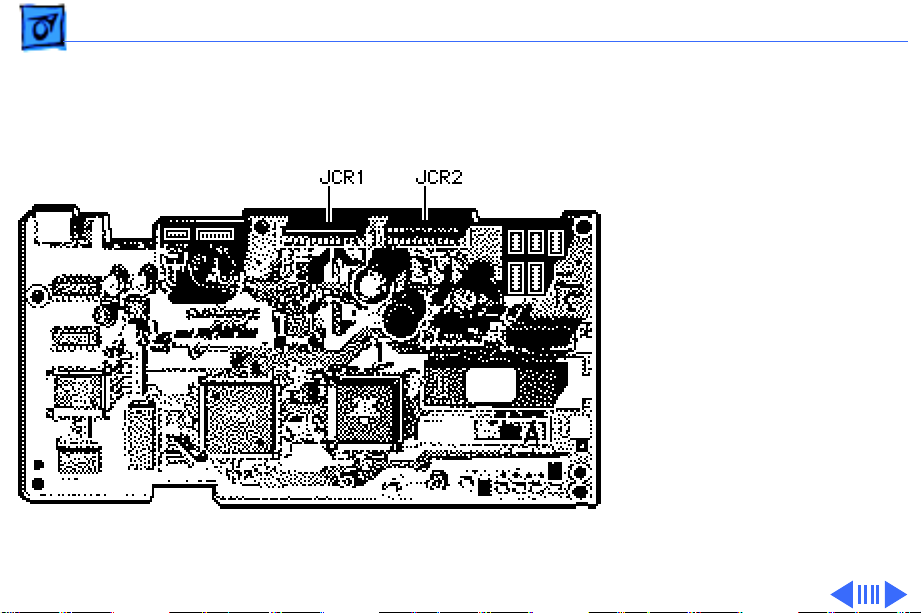
2 Disconnect the following
ribbon cables from the
controller board:
• JCR1
• JCR2
Page 51

Take Apart Controller Board - 16
3 Using a Phillips
screwdriver, remove
the four mounting
screws.
4 Remove the controller
board.
Controller
Board
Page 52
Take Apart Cut Sheet Feeder - 17
Cut Sheet Feeder
Cut Sheet Feeder
Before you begin, remove
the covers.
Caution:
precautions in Bulletins/
Safety.
Review the ESD
Page 53

Take Apart Cut Sheet Feeder - 18
1 Using a Phillips
screwdriver, remove
the two mounting
screws.
Page 54

Take Apart Cut Sheet Feeder - 19
2 Remove the wires from
the catch.
Catch
Page 55

Take Apart Cut Sheet Feeder - 20
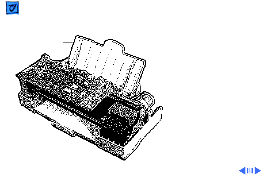
3 Press in the two latches
and remove the sheet
feeder from the printer.
Latch
Latch
Page 56

Take Apart Power Supply - 21
Power Supply
Before you begin, remove
the following:
• Covers
• Cut sheet feeder
Power Supply
Caution:
precautions in Bulletins/
Safety.
Note:
power supply, it is
necessary to run the Color
StyleWriter Pro Utility. See
“Color StyleWriter Pro
Utility” in the Adjustments
chapter.
Review the ESD
After replacing the
Page 57

Take Apart Power Supply - 22
1 Disconnect connector
JPOW1 from the
controller board.
2 Release the wires from
the holding tabs.
Holding Tabs
Page 58

Take Apart Power Supply - 23
3 Using a Phillips
screwdriver, loosen the
two mounting screws and
remove the power
supply.
Power Supply
Page 59

Take Apart Sensor Board - 24
Sensor Board
Before you begin, remove
the following:
• Covers
• Cut sheet feeder
Sensor Board
Caution:
precautions in Bulletins/
Safety.
Review the ESD
Page 60

Take Apart Sensor Board - 25
1 Disconnect connector
JASF1 from the
controller board.
Page 61

Take Apart Sensor Board - 26
2 Push out the two
mounting latches and
remove the sensor board.
LatchLatch
Sensor Board
Page 62

Take Apart Carriage Unit and Board - 27
Carriage Unit and Board
Before you begin, remove
the following:
• Covers
• Controller board
Carriage
Unit and
Board
Caution:
precautions in Bulletins/
Safety.
Caution:
magnetized screwdriver
near the encoder. A
magnetized screwdriver
will damage the encoder.
Review the ESD
Do not use a
Page 63

Take Apart Carriage Unit and Board - 28
Note:
After replacing the
carriage board, it is
necessary to run the Color
StyleWriter Pro Utility. See
“Color StyleWriter Pro
Utility” in the Adjustments
chapter.
Carriage
Unit and
Board
Page 64

Take Apart Carriage Unit and Board - 29
1 Advance the locking gear
Carriage Unit
and disengage the
carriage.
Page 65

Take Apart Carriage Unit and Board - 30
2 Move the carriage out of
the home position.
Carriage Unit
Print Heads
Caution:
The print heads
are now uncapped. Do not
leave them uncapped for
more than 12 hours or
they will dry out.
Caution:
Do not get the
printer’s ink on your
hands or clothes.
Although the ink is water
soluble, it contains dyes
that will stain.
Page 66

Take Apart Carriage Unit and Board - 31
3 Using a Phillips
screwdriver, loosen the
screw and push in the
carriage belt tensioner.
Carriage Belt
Tensioner
Page 67

Take Apart Carriage Unit and Board - 32
4 Remove the carriage
belt.
Carriage Belt
Page 68

Take Apart Carriage Unit and Board - 33
5 Remove the ferrite core.
Ferrite Core
Page 69

Take Apart Carriage Unit and Board - 34
6 Remove the plastic
mounting bracket.
Mounting
Bracket
Page 70

Take Apart Carriage Unit and Board - 35
7 Using a Phillips
screwdriver, remove
the shield plate mounting
screws.
8 Remove the shield plate.
Shield Plate
Page 71

Take Apart Carriage Unit and Board - 36
9 Pull up the front of the
carriage unit and release
Carriage Unit
it from the front
carriage rod.
Carriage Rod
Page 72

Take Apart Carriage Unit and Board - 37
10 Remove the scale spring.
Scale Spring
Page 73

Take Apart Carriage Unit and Board - 38
11 Press in the latches and
remove the scale holder
from the printer.
Scale Holder
Page 74

Take Apart Carriage Unit and Board - 39
12 Remove the shaft spring
from the carriage rod.
Shaft Spring
Carriage Rod
Page 75

Take Apart Carriage Unit and Board - 40
13 Pull the carriage to the
right and carefully
remove the carriage rod
from the chassis.
Carriage Unit
Page 76

Take Apart Carriage Unit and Board - 41
14
Caution:
Be careful not
to bend the encoder
when removing it from
the chassis.
Carefully remove the
encoder and carriage
unit from the printer.
Encoder
Replacement Note:
Make
sure the encoder is
installed in the proper
orientation in the scale
holder. Failure to do so
will cause an encoder
error to develop.
Page 77

Take Apart Carriage Unit and Board - 42
15
Caution:
Be careful not
to bend the encoder.
Carefully place the
carriage unit in front of
the printer.
Encoder
Carriage
Unit
Page 78

Take Apart Carriage Unit and Board - 43
16 Remove the flexible
cables from the
Flexible Cable
Flexible Cable
connectors on the
carriage board.
Page 79

Take Apart Carriage Unit and Board - 44
17 Release the latch and
remove the carriage
board and shield.
Latch
Carriage Board
and Shield
Page 80

Take Apart Carriage Unit and Board - 45
18 Remove the carriage belt
holder and belt.
Carriage Belt Holder
Carriage Belt
Page 81

Take Apart Carriage Unit and Board - 46
19 Open the carriage unit.
20 Remove the ribbon cable
holder and ribbon cable.
Ribbon Cable
Ribbon Cable Holder
Page 82

Take Apart Carriage Motor - 47
Carriage Motor
Before you begin, remove
the covers.
Caution: Review the ESD
precautions in Bulletins/
Safety.
Carriage
Motor
Page 83

Take Apart Carriage Motor - 48
1 Using a Phillips
screwdriver, loosen the
screw and push in the
carriage belt tensioner.
Carriage Belt
Tensioner
Page 84

Take Apart Carriage Motor - 49
2 Disconnect connector
JCRM1 from the
controller board.
3 Remove the wires from
the mounting bracket.
JCRM1
Mounting
Bracket
Page 85

Take Apart Carriage Motor - 50
4 Using a Phillips
screwdriver, remove
the two mounting
screws.
Mounting Screw
Mounting Screw
5 Remove the motor.
Page 86

Take Apart Printer Frame - 51
Printer Frame
Before you begin, remove
the following:
• Covers
Printer Frame
• Cut sheet feeder
• Power supply
Caution: Review the ESD
precautions in Bulletins/
Safety.
Page 87

Take Apart Printer Frame - 52
1 Release the right latch
and lift up on the
printer.
Right Latch
Page 88

Take Apart Printer Frame - 53
2 Release the left latch
and remove the printer
frame from the printer.
Left Latch
Page 89

Take Apart Ink Absorber Elements - 54
Ink Absorber Elements
Before you begin, remove
the following:
• Covers
• Controller board
• Carriage unit
Caution: Review the ESD
precautions in Bulletins/
Safety.
Caution: Do not get the
printer’s ink on your hands
or clothes. Although the ink
Ink Absorber
Elements
is water soluble, it contains
dyes that will stain.
Page 90

Take Apart Ink Absorber Elements - 55
1 Turn over the carriage
Sub Absorber Element
unit.
2 Using a small flat-blade
screwdriver, gently
release the two latches
and remove the main
absorber element.
3 Gently release the
remaining two latches
and remove the sub
absorber element.
Main Absorber Element
Page 91

Take Apart Ink Absorber Plates - 56
Ink Absorber Plates
Before you begin, remove
the following:
Ink Absorber Plates
• Covers
• Sheet feeder
• Printer frame
Caution” Review the ESD
precautions in Bulletins/
Safety.
Caution: Do not get the
printer’s ink on your hands
or clothes. Although the ink
is water soluble, it contains
dyes that will stain.
Page 92
Take Apart Ink Absorber Plates - 57
Note: After replacing the ink
absorber plates, it is
necessary to run the Color
StyleWriter Pro Utility. See
“Color StyleWriter Pro
Ink Absorber Plates
Utility” in the Adjustments
chapter.
Page 93

Take Apart Ink Absorber Plates - 58
1 Release the front latch.
Side Latch
2 Release the two side
latches and remove the
ink absorber cover.
Front Latch
Ink Absorber
Cover
Side Latch
Page 94

Take Apart Ink Absorber Plates - 59
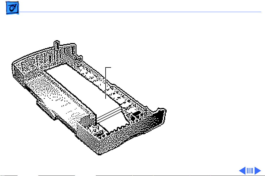
3 Remove the three ink
absorber plates.
Ink Absorber
Plates
Page 95

Take Apart Paper Feed Motor - 60
Paper Feed Motor
Before you begin, remove
the following:
• Covers
• Cut sheet feeder
• Power supply
• Printer frame
Caution: Review the ESD
precautions in Bulletins/
Safety.
Paper Feed Motor
Page 96

Take Apart Paper Feed Motor - 61
1 Disconnect connector
JLFM1 from the
controller board.
2 Release the wires from
the mounting bracket.
Mounting Bracket
Page 97

Take Apart Paper Feed Motor - 62
3 Note: Remove the paper
feed motor carefully to
avoid losing the gear.
Using a Phillips
screwdriver, remove
the two mounting
screws and remove the
paper feed motor.
Gear
Paper Feed Motor
Page 98
Take Apart Paper Guide - 63
Paper Guide
Before you begin, remove
the following:
• Covers
• Cut sheet feeder
• Power supply
• Printer frame
Caution: Review the ESD
precautions in Bulletins/
Paper Guide
Safety.
Page 99

Take Apart Paper Guide - 64
1 Disconnect ribbon cables
JCR1 and JCR2 from the
controller board.
Page 100

Take Apart Paper Guide - 65
2 Release the latches on
the ferrite core and
remove the core and the
ribbon cables.
Ferrite Core
 Loading...