


Instruction Manual
COMMERCIAL GAS WATER HEATERS
Ashland City, TN 37015 |
www.hotwater.com |
ANSI / NSF 5 |
POWER VENT/POWER DIRECT VENT GAS MODELS WITH HOT SURFACE IGNITION
• For Your Safety •
AN ODORANT IS ADDED TO THE GAS USED
Thank you for buying this energy efficient water heater. BY THIS WATER HEATER. We appreciate your confidence in our products.
ALL TECHNICAL AND WARRANTY QUESTIONS: SHOULD BE DIRECTED TO THE LOCAL DEALER FROM WHOM THE WATER HEATER WAS
PURCHASED. IF YOU ARE UNSUCCESSFUL, CALL THE TECHNICAL SUPPORT PHONE NUMBER SHOWN ON THE WATER HEATER LABELING.
|
Keep this manual in the pocket on heater for future reference |
|
|
PRINTED 0310 |
whenever maintenance adjustment or service is required. |
317445-000 |
|
1 |
|||
|
|

table of contents
table of contents........................................................................ |
2 |
safe installation, use and service........................................ |
3 |
APPROVALS......................................................................................... |
3 |
general safety information.................................................... |
4 |
Precautions........................................................................................... |
4 |
Grounding Instructions.......................................................................... |
4 |
Hydrogen Gas Flammable.................................................................... |
4 |
troubleshooting.......................................................................... |
6 |
introduction................................................................................... |
7 |
Abbreviations Used............................................................................... |
7 |
Qualifications......................................................................................... |
7 |
Qualified Installer or Service Agency.............................................. |
7 |
iCOMM™ & BACnet Compatible.......................................................... |
7 |
Preparing For The Installation............................................................... |
7 |
features and components........................................................ |
8 |
installation consideration...................................................... |
9 |
Rough in Dimensions............................................................................ |
9 |
Locating The Water Heater................................................................. |
10 |
Insulation Blankets.............................................................................. |
11 |
Combustion Air and Ventilation........................................................... |
11 |
Unconfined Space............................................................................... |
11 |
Unusually Tight Construction........................................................ |
12 |
Confined Space................................................................................... |
12 |
Direct Vent Appliances.................................................................. |
12 |
Exhaust Fans................................................................................ |
12 |
Louvers and Grilles....................................................................... |
12 |
Fresh Air Openings For Confined Spaces........................................... |
12 |
Outdoor Air Through Two Openings.................................................... |
12 |
Outdoor Air Through One Opening..................................................... |
12 |
Outdoor Air Through Two Horizontal Ducts......................................... |
13 |
Air From Other Indoor Spaces............................................................ |
13 |
installing the new water heater......................................... |
14 |
Chemical Vapor Corrosion.................................................................. |
14 |
Water Piping........................................................................................ |
14 |
Power Supply...................................................................................... |
14 |
Power Fluctuations and Electrical Noise....................................... |
14 |
Dedicated Power Wiring and Breakers......................................... |
14 |
Polarity Sensitive........................................................................... |
14 |
Mixing Valves...................................................................................... |
15 |
Dishwashing Machines....................................................................... |
15 |
Space Heating and Potable Water System......................................... |
15 |
Closed Water Systems........................................................................ |
15 |
Thermal Expansion............................................................................. |
16 |
Temperature-Pressure Relief Valve.................................................... |
17 |
T&P Valve Discharge Pipe Requirements:.................................... |
17 |
Gas Piping........................................................................................... |
18 |
Condensate Piping.............................................................................. |
18 |
High Altitude Installations.............................................................. |
19 |
Sediment Traps............................................................................. |
19 |
Filling the Water Heater...................................................................... |
19 |
Venting................................................................................................ |
20 |
Vent Pipe Termination................................................................... |
20 |
Planning the Vent System............................................................. |
20 |
Installation of Vent System............................................................ |
21 |
Vent Terminal Installation, Sidewall............................................... |
21 |
Installation Requirements - Commonwealth of Massachusetts.......... |
22 |
Installation of Carbon Monoxide Detectors......................................... |
22 |
Approved Carbon Monoxide Detectors............................................... |
22 |
Signage............................................................................................... |
22 |
Exemptions......................................................................................... |
22 |
Manufacturer Requirements-Gas Equipment Venting Sytem Provided... |
22 |
Manufacturer Requirements-Gas Equipment Venting Sytem Not Provided... |
22 |
Termination Clearances Sidewall Power Vent..................................... |
23 |
Termination Clearances Sidewall Direct Vent..................................... |
24 |
Sequence of Installations, Figure 18A........................................... |
25 |
Direct Vent Terminal Installation.................................................... |
25 |
Installation Sequence.................................................................... |
25 |
Vent Terminals Supplied with Heater Must be Used..................... |
25 |
Vertical Vent Terminal Installation.................................................. |
26 |
Concentric Vent Installation........................................................... |
27 |
Kit Components............................................................................. |
27 |
Safety Considerations................................................................... |
27 |
Installation Procedure 1 Roof Termination, see Figure C............. |
27 |
direct vent diagram.................................................................. |
30 |
Vent Pipe Preparation......................................................................... |
31 |
Primer............................................................................................ |
31 |
Primer and Cement....................................................................... |
31 |
Applicators..................................................................................... |
31 |
Controls and Switches........................................................................ |
33 |
Blower Prover Switch.................................................................... |
33 |
Blocked Exhaust Switch................................................................ |
33 |
Blocked Intake Switch................................................................... |
33 |
On/Off Switch................................................................................ |
33 |
Hot Surface Igniter........................................................................ |
33 |
temperature regulation......................................................... |
36 |
Hi Limit Switch (E.C.O.)................................................................. |
36 |
control system operation..................................................... |
37 |
Overview............................................................................................. |
37 |
Commercial And Residential Models............................................ |
37 |
Control System Navigation.................................................................. |
37 |
User Input Buttons......................................................................... |
37 |
The Desktop Screen...................................................................... |
37 |
Status Icons................................................................................... |
38 |
Operating States........................................................................... |
39 |
Control System Menus.................................................................. |
39 |
User Settings & Control System Menus.............................................. |
40 |
Temperatures................................................................................ |
40 |
Operating Set Point And Differential Adjustment........................... |
40 |
Temperatures (cont)...................................................................... |
41 |
Heater Status................................................................................ |
41 |
Display Settings............................................................................. |
42 |
Heater Information......................................................................... |
42 |
Current Fault................................................................................. |
43 |
Fault History.................................................................................. |
43 |
Fault Occurrence........................................................................... |
43 |
Restore Factory Defaults............................................................... |
43 |
Service Contact Information.......................................................... |
44 |
for your information............................................................... |
45 |
Start Up Conditions............................................................................. |
45 |
Smoke/Odor.................................................................................. |
45 |
Thermal Expansion....................................................................... |
45 |
Operational Conditions........................................................................ |
45 |
Smelly Water................................................................................. |
45 |
“Air” in Hot Water Faucet............................................................... |
45 |
periodic maintenance................................................................ |
46 |
Venting System Inspection.................................................................. |
46 |
Anode Rod Inspection......................................................................... |
46 |
Temperature-Pressure Relief Valve Operation.................................... |
46 |
Draining and Flushing......................................................................... |
46 |
To Drain the Water Heater Storage Tank............................................ |
47 |
To Flush the Water Heater Storage Tank............................................ |
47 |
Service................................................................................................ |
47 |
maintenance.................................................................................. |
48 |
Temperature-Pressure Relief Valve Test............................................. |
48 |
leakage checkpoints................................................................ |
49 |
troubleshooting........................................................................ |
50 |
Installation Checklist........................................................................... |
50 |
Water Heater Location.................................................................. |
50 |
Venting.......................................................................................... |
50 |
Gas Supply and Piping.................................................................. |
50 |
Condensate Drain......................................................................... |
50 |
Electrical Connections................................................................... |
50 |
Installation Checklist........................................................................... |
50 |
Sequence Of Operation Flow Chart.................................................... |
51 |
Operational Problems......................................................................... |
52 |
Rough Starting, Rough Operation................................................. |
52 |
Momentary Ignition........................................................................ |
52 |
Not Enough Or No Hot Water........................................................ |
52 |
Water Is Too Hot............................................................................ |
52 |
Noisy Operation............................................................................. |
52 |
Replacement Parts........................................................................ |
52 |
Fault and Alert Conditions................................................................... |
52 |
Fault Conditions............................................................................ |
52 |
Alert Conditions............................................................................. |
52 |
Resetting Control System Lock Outs............................................ |
53 |
Diagnostic Checks......................................................................... |
53 |
Fault and Alert Messages.............................................................. |
54 |
notes................................................................................................ |
56 |
Limited Warranty......................................................................... |
59 |
2

safe installation, use and service
The proper installation, use and servicing of this water heater is extremely important to your safety and the safety of others.
Many safety-related messages and instructions have been provided in this manual and on your own water heater to warn you and others of a potential injury hazard. Read and obey all safety messages and instructions throughout this manual. It is very important that the meaning of each safety message is understood by you and others who install, use, or service this water heater.
This is the safety alert symbol. It is used to alert you to potential personal injury hazards. Obey all safety messages that follow this symbol to avoid possible injury or death.
DANGER indicates an imminently
DANGER hazardous situation which, if not avoided, will result in injury or death.
WARNING indicates a potentially hazardous
WARNING situation which, if not avoided, could result in injury or death.
CAUTION indicates a potentially hazardous
CAUTION situation which, if not avoided, could result in minor or moderate injury.
CAUTION used without the safety alert CAUTION symbol indicates a potentially hazardous
situation which, if not avoided, could result in property damage.
All safety messages will generally tell you about the type of hazard, what can happen if you do not follow the safety message, and how to avoid the risk of injury.
The California Safe Drinking Water and Toxic Enforcement Act requires the Governor of California to publish a list of substances known to the State of California to cause cancer, birth defects, or other reproductive harm, and requires businesses to warn of potential exposure to such substances.
This product contains a chemical known to the State of California to cause cancer, birth defects, or other reproductive harm. This appliance can cause low level exposure to some of the substances listed in the Act.
APPROVALS
ANSI / NSF 5
3

general safety information
Precautions
DO NOT USE THIS APPLIANCE IF ANY PART HAS BEEN UNDER
WATER. Immediately call a qualified service agency to inspect the appliance and to make a determination on what steps should be taken next.
If the unit is exposed to the following, do not operate heater until all corrective steps have been made by a qualified service agency.
1.External fire.
2.Damage.
3.Firing without water.
Hydrogen Gas Flammable
Explosion Hazard
 Flammable hydrogen gases may be present.
 Keep all ignition sources away from faucet when turning on hot water.
GROUNDING INSTRUCTIONS
This water heater must be grounded in accordance with the National Electrical Code and/or local codes. These must be followed in all cases. Failure to ground this water heater properly may also cause erratic control system operation.
This water heater must be connected to a grounded metal, permanent wiring system; or an equipment grounding conductor must be run with the circuit conductors and connected to the equipment grounding terminal or lead on the water heater.
Hydrogen gas can be produced in a hot water system served by this appliance that has not been used for a long period of time (generally two weeks or more). Hydrogen gas is extremely flammable. To reduce the risk of injury under these conditions, it is recommended that a hot water faucet served by this appliance be opened for several minutes before using any electrical appliance connected to the hot water system. If hydrogen is present there will probably be an unusual sound such as air escaping through the pipe as the water begins to flow. There should be no smoking or open flame near the faucet at the time it is open.
Verify the power to the water heater is turned off before performing any service procedures.
Read and understand this instruction manual and the safety messages herein before installing, operating or servicing this water heater.
Failure to follow these instructions and safety messages could result in death or serious injury.
This manual must remain with the water heater.
Water temperature over 125°F (52°C) can cause severe burns instantly resulting in severe injury or death.
Children, the elderly and the physically or mentally disabled are at highest risk for scald injury.
Feel water before bathing or showering.
Temperature limiting devices such as mixing valves must be installed when required by codes and to ensure safe temperatures at fixtures.
Explosion Hazard
 Overheated water can cause water tank explosion.
 Properly sized temperature and pressure relief valve must be installed in the opening provided.
CAUTION
Improper installation, use and service may result in property damage.
•Do not operate water heater if flood damaged.
•Inspect and anode rods regularly, replace if damaged.
•Install in location with drainage.
•Fill tank with water before operation.
•Properly sized thermal expansion tanks are required on all closed water systems.
Refer to this manual for installation and service.
4

general safety information
5

General Safety Information
Fire or Explosion Hazard
 Do not store or use gasoline or other flammable vapors and liquids in the vicinity of this or any other appliance.
 Avoid all ignition sources if you smell gas.
 Do not expose water heater controls to excessive gas pressure.
 Use only the gas shown on the water heater rating plate.
 Maintain required clearances to combustibles.
 Keep ignition sources away from faucets after extended periods of non-use.
Read instruction manual before installing, using or servicing water heater.
Breathing Hazard - Carbon Monoxide Gas
 Do not obstruct water heater air intake
with insulating blanket.
 Gas and carbon monoxide detectors
are available.
 Install water heater in accordance with
the instruction manual.
Breathing carbon monoxide can cause brain damage or death. Always read and understand instruction manual.
CAUTION
Property Damage Hazard
•All water heaters eventually leak.
•Do not install without adequate drainage.
Electrical Shock Hazard
•Turn off power to the water heater before performing any service.
•Label all wires prior to disconnecting when performing service. Wiring errors can cause improper and dangerous operation.
•Verify proper operation after servicing.
•Failure to follow these instructions can result in personal injury or death.
Fire Hazard
For continued protection against risk of fire:
 Do not install water heater on carpeted floor.
 Do not operate water heater if flood damaged.
Fire and Explosion Hazard
 Use joint compound or Teflon tape compatible with propane gas.
 Leak test before placing the water heater in operation.
 Disconnect gas piping and main gas shutoff valve before leak testing.
 Install sediment trap in accordance with NFPA 54.
Fire and Explosion Hazard
 Do not use water heater with any gas other than the gas shown on the rating plate.
 Excessive gas pressure to gas valve can cause serious injury or death.
 Turn off gas lines during installation.
 Contact a qualified installer or service agency for installation and service.
Jumping out control circuits or components can result in property damage, personal injury or death.
•Service should only be performed by a qualified service agent using proper test equipment.
•Altering the water heater controls and/or wiring in any way could result in permanent damage to the controls or water heater and is not covered under the limited warranty.
•Altering the water heater controls and/or wiring in any way could result in altering the ignition sequence allowing gas to flow to the main burner before the hot surface igniter is at ignition temperature causing delayed ignition which can cause a fire or explosion.
Any bypass or alteration of the water heater controls and/or wiring will result in voiding the appliance warranty.
6

introduction
Thank You for purchasing this water heater. Properly installed and maintained, it should give you years of trouble free service.
Abbreviations Used
Abbreviations found in this Instruction Manual include :
•ANSI - American National Standards Institute
•ASME - American Society of Mechanical Engineers
•GAMA - Gas Appliance Manufacturer’s Association
•NEC - National Electrical Code
•NFPA - National Fire Protection Association
•UL - Underwriters Laboratory
•CSA - Canadian Standards Association
Qualifications
Qualified Installer or Service Agency
Installation and service of this water heater requires ability equivalent to that of a Qualified Agency (as defined by ANSI below) in the field involved. Installation skills such as plumbing, air supply, venting, gas supply and electrical supply are required in addition to electrical testing skills when performing service.
ANSI Z223.1 2006 Sec. 3.3.83: “Qualified Agency” - “Any individual, firm, corporation or company that either in person or through a representative is engaged in and is responsible for (a) the installation, testing or replacement of gas piping or (b) the connection, installation, testing, repair or servicing of appliances and equipment; that is experienced in such work; that is familiar with all precautions required; and that has complied with all the requirements of the authority having jurisdiction.”
If you are not qualified (as defined by ANSI above) and licensed or certified as required by the authority having jurisdiction to perform a given task do not attempt to perform any of the procedures described in this manual. If you do not understand the instructions given in this manual do not attempt to perform any procedures outlined in this manual.
iCOMM™ & BACnet Compatible
ThiswaterheateriscompatiblewiththeiCOMM™remotemonitoring system. The iCOMM™ system hardware and monitoring service is purchased separately. It allows users to monitor critical operational, diagnostic and energy usage data from a secure web site.
The iCOMM™ system can automatically notify selected personnel via email and/or cellular phone text messages if operational problems or user defined Alert Conditions occur.
iCOMM™ system hardware is compatible with BACnet compliant supervisory controls and building management systems. For more information call 888 928-3702.
Preparing For The Installation
1.Read the entire manual before attempting to install or operate the water heater. Pay close attention to the General Safety Information on page 4 through 6. If you don’t follow the safety rules, the water heater may not operate safely. It could cause property damage, injury and/or death.
This manual contains instructions for the installation, operation, and maintenance of the water heater. It also contains warnings throughout the manual that you must read and be aware of. All warnings and all instructions are essential to the proper operation of the water heater and your safety.
Detailed installation diagrams are also found in this manual.
These diagrams will serve to provide the installer with a reference. It is essential that all venting, water piping, gas piping and wiring be installed as shown.
Particular attention should be given to the installation of thermometers at the locations indicated in the piping diagrams as these are necessary for checking the operation of the water heater.
The principal components of the water heater are identified in Features And Components on page 8 in this manual. Use this reference to locate and identify various components on the water heater.
See the Installation Checklist and Troubleshooting on page 50. By using this checklist the user may be able to make minor operational adjustments and avoid unnecessary service calls. However, service and diagnostic procedures should only be performed by a Qualified Service Agency.
Note: Costs to correct installation errors are not covered under the limited warranty.
2.Be sure to turn off power when working on or near the electrical system of the water heater. Never touch electrical components with wet hands or when standing in water.
3.The installation must conform to all instructions contained in this manual and the local code authority having jurisdiction. These shall be carefully followed in all cases. Authorities having jurisdiction should be consulted before installation begins if there are any questions regarding compliance with local, state or national codes.
In the absence of local codes, the installation must comply with the current editions of the National Fuel Gas Code,ANSI Z223.1/ NFPA 54 and the National Electrical Code, NFPA 70 or CAN/
CSA-B149.1, the Natural Gas and Propane Installation Code and CSA C22.1, the Canadian Electrical Code. All documents are available from the Canadian Standards Association, 8501
East Pleasant Valley Road, Cleveland, OH 44131. NFPA documents are also available from the National Fire Protection Association, 1 Batterymarch Park, Quincy, MA 02269.
4.If after reading this manual you have any questions or do not understand any portion of the instructions, call the toll free number on the back cover of this manual for technical assistance. In order to expedite your request, please have the full Model, Serial and Series number of the water heater you are working with available for the technician. This information is located on the water heater’s rating plate.
5.Carefully plan the placement of the water heater. Examine the location to ensure that it complies with the requirements in Locating The Water Heater on page 10 and the Rough In
Dimensions on page 9.
.
6.For installation in California this water heater must be braced or anchored to avoid falling or moving during an earthquake. See instructions for correct installation procedures. Instructions may be obtained from California Office of the State Architect, 1102 Q Street, Suite 5100, Sacramento, CA 95811.
7.Massachusetts Code requires this water heater to be installed in accordance with Massachusetts 248-CMR 2.00: State Plumbing Code and 248-CMR 5. See Commonwealth of Massachusetts on page 22.
7
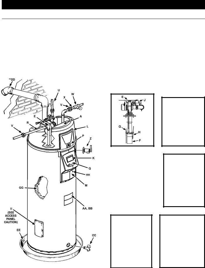
features and components
GET TO KNOW YOUR WATER HEATER - GAS MODELS
AControl Assembly
BBlocked Inlet Switch
CBlocked Outlet Switch
DFan Prover Switch
EBlower Assembly
FBurner Assembly
GFlame Sensor
HHot Surface Igniter
IJunction Box
JGas Valve Assembly
KDisplay Board
LTop Plastic Enclosure
MDisplay Enclosure
**N Exhaust Elbow Assembly
**O Condensate Tubing
POff/On Switch
QDisplay Label
RHot Water Outlet
TGas Supply
UMain Manual Gas Shutoff Valve
VUnion
WInlet Water Shutoff Valve
XCold Water Inlet
YInlet Dip Tube
ZT/P Relief Valve
AARating Plate
BBLabels
CCDrain Valve
**DD Vent Terminal
EEDrain Pan
FFAnode
GGInsulation
HHUpper Temperature Probe
IIAccess Door
REPLACEMENT PARTS AND DELIMING PRODUCTS
Replacement parts and recommended delimer may be ordered through authorized servicers or distributors. When ordering parts, provide complete model and serial numbers (see rating plate), quantity and name of part desired. Standard hardware items may be purchased locally.
ACCESS PANEL
Caution: Thisaccesspanelcovers a 2” NPT plug that was required during the manufacturing of this water heater. This 2” NPT flange is notacleanoutfitting, removing the
2”NPTplugandusingthisfittingasa cleanout could void your warranty.
VACUUM RELIEF
VALVE
*INSTALL PER LOCAL CODES
* CAUTION HARNESS HAS 120 VAC. IN OPERATION.
** See “Planning the Vent System,” “Installation of Vent System” and “Condensate Piping” for more information.
FIGURE 1.
8

installation consideration
ROUGH IN DIMENSIONS
FIGURE 1A.
Rough-In-Dimensions |
|
|
|
|
|
|
|
|
|
|
|
|
|
|
|
|
|
|
|
|
|
|
|
|
|
|
||||||||
|
|
|
|
|
|
|
|
|
|
|
|
|
|
|
|
|
|
|
|
|
|
|
|
|
|
|
|
|
|
|
|
|
|
|
Units |
|
|
A |
|
B |
|
C |
|
|
D |
|
|
E |
|
F |
|
|
|
|
|
|
|
|
|
|
|
|
|
|
|||||
Inches |
|
66.75 |
|
49.25 |
|
22.00 |
|
15.75 |
|
3.00 |
|
8.00 |
|
|
|
|
|
|
|
|
|
|
|
|
|
|
||||||||
cm |
|
169.5 |
|
125.09 |
|
55.88 |
|
40.00 |
|
7.62 |
|
20.32 |
|
|
|
|
|
|
|
|
|
|
|
|
|
|
||||||||
Top/Side Inlet and Outlet: 3/4” NPT |
|
|
|
|
|
|
|
|
|
|
|
|
|
|
|
|
|
|
|
|
|
|
||||||||||||
Gas Inlet: 1/2” NPT |
|
|
|
|
|
|
|
|
|
|
|
|
|
|
|
|
|
|
|
|
|
|
|
|
|
|
||||||||
Capacity, Gas and Electrical Characteristics |
|
|
|
|
|
|
|
|
|
|
|
|
|
|
|
|
||||||||||||||||||
|
|
|
|
|
|
|
|
|
|
|
|
|
|
|
|
|
|
|
|
|
|
|
|
|
|
|
||||||||
Approximate Capacity |
|
|
Manifold Pressure |
|
Electrical Characteristics |
|
|
|
|
|
|
|
|
|
||||||||||||||||||||
U.S. Gals. |
|
Liters |
|
Gas Type |
|
“WC |
|
kPA |
|
Volts/Hz |
Amperes |
|
|
|
|
|
|
|
|
|
||||||||||||||
50 |
|
|
|
189 |
|
|
|
Nat./LP |
|
|
0” |
|
|
0” |
|
120/60 |
|
|
|
<5 |
|
|
|
|
|
|
|
|
|
|||||
All models - Maximum Supply Pressure: 14 inches W.C. (3.48kPa) |
|
|
|
|
|
|
|
|
|
|
|
|||||||||||||||||||||||
Minimum Supply Pressure for Natural Gas: 3.50” (.87kPa) |
|
|
|
|
|
|
|
|
|
|
|
|
||||||||||||||||||||||
Minimum Supply Pressure for Propane Gas: 8.00” (1.99kPa) |
|
|
|
|
|
|
|
|
|
|
|
|
||||||||||||||||||||||
Minimum pressure must be maintained under both load and no load (dynamic and static) conditions. |
|
|
|
|||||||||||||||||||||||||||||||
Recovery Capacities - U.S. Gallons/Hr. and Liters/Hr. at Temperature Rise Indicated |
|
|
|
|
|
|
||||||||||||||||||||||||||||
|
|
|
|
|
|
|
|
|
|
|
|
|
|
|
|
|
|
|
|
|
|
|
|
|
|
|
|
|
|
|
||||
|
Input |
|
|
|
|
|
|
|
|
|
|
|
|
|
|
|
|
|
|
Recovery Capacities |
|
|
|
|
|
|
||||||||
Rating |
|
Rating |
|
|
Temp. |
F |
|
30 |
|
|
40 |
|
50 |
|
|
60 |
|
70 |
|
80 |
|
90 |
100 |
110 |
120 |
130 |
140 |
|||||||
(Btu/hr) |
|
(kW) |
|
|
Rise |
|
C |
|
17 |
|
|
22 |
|
28 |
|
|
33 |
|
39 |
|
44 |
|
50 |
56 |
61 |
67 |
72 |
78 |
||||||
|
|
|
|
|
|
|
|
|
|
|
|
|
|
|
|
|
|
|
|
|
||||||||||||||
|
|
|
|
|
|
|
|
|
|
|
|
|
|
|
|
|
|
|
|
|
|
|
|
|
|
|
|
|
|
|
|
|
||
100,000 |
|
29.3 |
|
|
|
GPH |
|
|
387 |
|
|
291 |
|
233 |
|
|
194 |
|
166 |
145 |
|
129 |
116 |
106 |
97 |
90 |
83 |
|||||||
|
|
|
|
LPH |
|
|
1465 |
|
1102 |
|
882 |
|
|
734 |
|
628 |
549 |
|
488 |
439 |
401 |
367 |
341 |
314 |
||||||||||
|
|
|
|
|
|
|
|
|
|
|
|
|
|
|
|
|
|
|||||||||||||||||
|
|
|
|
|
|
|
|
|
|
|
|
|
|
|
|
|
|
|
|
|
|
|
|
|
|
|
|
|
|
|
|
|
|
|
Recovery capacity based on 96% thermal efficiency
9

Locating The Water Heater
Carefully choose a location for the new water heater. The placement is a very important consideration for the safety of the occupants in the building and for the most economical use of the appliance.
CAUTION
Property Damage Hazard
•All water heaters eventually leak.
•Do not install without adequate drainage.
Whether replacing an existing water heater or installing the water heater in a new location observe the following critical points:
1.The water heater must be located indoors.
2.The water heater must not be located in an area where it will be subject to freezing temperatures.
3.Locate the water heater so it is protected and not subject to physical damage by a moving vehicle.
4.Locate the water heater on a level surface.
5.Locate the water heater near a floor drain. The water heater should be located in an area where leakage of the tank or connections will not result in damage to the area adjacent to the water heater or to lower floors of the structure. When such locations cannot be avoided, it is recommended that a metal drain pan, adequately drained, be installed under the appliance.
6.Locate the water heater close to the point of major hot water usage.
7.Locate the water heater close to a 120 VAC power supply. See Power Supply on page 14 for requirements.
8.Locate the water heater where an adequate supply of fresh air for combustion and ventilation can be obtained. See Combustion
Air and Ventilation on page 11.
9.Locate the water heater where the vent and intake air piping, when installed, will remain within the maximum equivalent lengths allowed. See Venting on page 20.
10.Do not locate the water heater where noise (such as the Combustion Blower) during normal operation will be objectionable in adjacent areas.
11.Do not locate the water heater where the subsequent installation of the vent (exhaust) or intake air terminations would be objectionable due to noise at the termination(s). This includes locations close to or across from windows and doors. See
Venting starting on page 20.
INSTALLATIONS IN AREAS WHERE FLAMMABLE LIQUIDS
(VAPORS) ARE LIKELY TO BE PRESENT OR STORED (GARAGES, STORAGE AND UTILITY AREAS, ETC.): Flammable liquids (such as gasoline, solvents, propane (LP or butane, etc.) and other substances (such as adhesives, etc.) emit flammable vapors which can be ignited by a gas water heater’s hot surface igniter or main burner. The resulting flashback and fire can cause death or serious burns to anyone in the area.
Also, the water heater must be located and/or protected so it is not subject to physical damage by a moving vehicle.
This water heater must not be installed directly on carpeting. Carpeting must be protected by metal or wood panel beneath the appliance extending beyond the full width and depth of the appliance by at least 3” (7.6 cm) in any direction, or if the appliance is installed
10
in an alcove or closet, the entire floor must be covered by the panel. Failure to heed this warning may result in a fire hazard.
Minimum clearances between the water heater and combustible construction are 0 inch at the sides and rear, 5.5” (14.0 cm) from the front and 18” (45.7 cm) from the top. (Standard clearance.) If clearances stated on the heater differ from standard clearances, install water heater according to clearances stated on the heater.
Adequate clearance 30” (76 cm) for servicing this appliance should be considered before installation, such as changing the anodes, control system components and gas valve.
A minimum clearance of 5.5” (14.0 cm) must be allowed for access to replaceable and/or serviceable parts such as the thermostats, drain valve, condensate drain, relief valve, clean out opening, and the vent connection (exhaust elbow).
When installing the heater, consideration must be given to proper location.Locationselectedshouldbeasclosetothewallaspracticable and as centralized with the water piping system as possible.
•Do not apply insulation to the top of the water heater, as this will interfere with safe operation of the blower assembly.
•Do not cover the outer door, thermostat or temperature & pressure relief valve.
•Do not cover the instruction manual. Keep it on the side of the water heater or nearby for future reference.
•Do obtain new warning and instruction labels from the manufacturer for placement on the blanket directly over the existing labels.
COMBUSTION AIR AND VENTILATION
A gas water heater cannot operate properly without the correct amount of air for combustion. Do not install in a confined area such as a closet, unless you provide air as shown in the “Facts to Consider About Location” section. Never obstruct the flow of ventilation air. If you have any doubts or questions at all, call your gas supplier. Failure to provide the proper amount of combustion air can result in a fire or explosion and cause death, serious bodily injury, or property damage.
FIGURE 2.
INSULATION BLANKETS
Insulationblanketsareavailabletothegeneralpublicforexternaluseon gaswaterheatersbutarenotnecessarywiththeseproducts.Thepurpose of an insulation blanket is to reduce the standby heat loss encountered with storage tank heaters. Your water heater meets or exceeds the Energy PolicyAct standards with respect to insulation and standby loss requirements, making an insulation blanket unnecessary.
Should you choose to apply an insulation blanket to this heater, you should follow these instructions (For identification of components mentioned below, see Figure 1). Failure to follow these instructions can restrict the air flow required for proper combustion, potentially resulting in fire, asphyxiation, serious personal injury or death.
FIGURE 3.
If this water heater will be used in beauty shops, barber shops, cleaning establishments, or self-service laundries with dry cleaning equipment, it is imperative that the water heater (s) be installed direct vent so that all air for combustion and ventilation is taken from outdoors.
Propellants of aerosol sprays and volatile compounds, (cleaners, chlorine based chemicals, refrigerants, etc.) in addition to being highly flammable in many cases, will also react to form corrosive hydrochloric acid when exposed to the combustion products of the water heater. The results can be hazardous, and also cause product failure.
Unconfined Space
An Unconfined Space is one whose volume is not less than 50 cubic feet per 1,000 Btu/hr (4.8 cubic meters per kW) of the total input rating of all appliances installed in the space. Rooms communicating directly with the space, in which the appliances are installed, through openings not furnished with doors, are considered a part of the unconfined space.
Makeup air requirements for the operation of exhaust fans, kitchen
11
ventilation systems, clothes dryers and fireplaces shall also be considered in determining the adequacy of a space to provide combustion, ventilation and dilution air.
Unusually Tight Construction
In unconfined spaces in buildings, infiltration may be adequate to provide air for combustion, ventilation and dilution of flue gases. However, in buildings of unusually tight construction (for example, weather stripping, heavily insulated, caulked, vapor barrier, etc.) additional air must be provided using the methods described in the Confined Space section that follows.
Confined Space
A Confined Space is one whose volume is less than 50 cubic feet per 1,000 Btu/hr (4.8 cm per kW) of the total input rating of all appliances installed in the space.
Openings must be installed to provide fresh air for combustion, ventilation and dilution in confined spaces. The required size for the openings is dependent on the method used to provide fresh air to the confined space and the total Btu/hr input rating of all appliances installed in the space.
Direct Vent Appliances
Appliances installed in a Direct Vent configuration that derive all air for combustion from the outdoor atmosphere through sealed intake air piping are not factored in the total appliance input Btu/hr calculations used to determine the size of openings providing fresh air into confined spaces.
Exhaust Fans
Where exhaust fans are installed, additional air shall be provided to replace the exhausted air. When an exhaust fan is installed in the same space with a water heater, sufficient openings to provide fresh air must be provided that accommodate the requirements for all appliances in the room and the exhaust fan. Undersized openings will cause air to be drawn into the room through the water heater’s vent system causing poor combustion. Sooting, serious damage to the water heater and the risk of fire or explosion may result. It can also create a risk of asphyxiation.
Louvers and Grilles
The free areas of the fresh air openings in the instructions that follow do not take in to account the presence of louvers, grilles or screens in the openings.
The required size of openings for combustion, ventilation and dilution air shall be based on the “net free area” of each opening. Where the free area through a design of louver or grille or screen is known, it shall be used in calculating the size of opening required to provide the free area specified. Where the louver and grille design and free area are not known, it shall be assumed that wood louvers will have 25% free area and metal louvers and grilles will have 75% free area. Non motorized louvers and grilles shall be fixed in the open position.
Fresh Air Openings For Confined Spaces
The following instructions shall be used to calculate the size, number and placement of openings providing fresh air for combustion, ventilation and dilution in confined spaces. The illustrations shown in this section of the manual are a reference for the openings that provide fresh air into confined spaces only. Do not refer to these illustrationsforthepurposeofventinstallation.SeeVentingInstallation on page 20 for complete venting installation instructions.
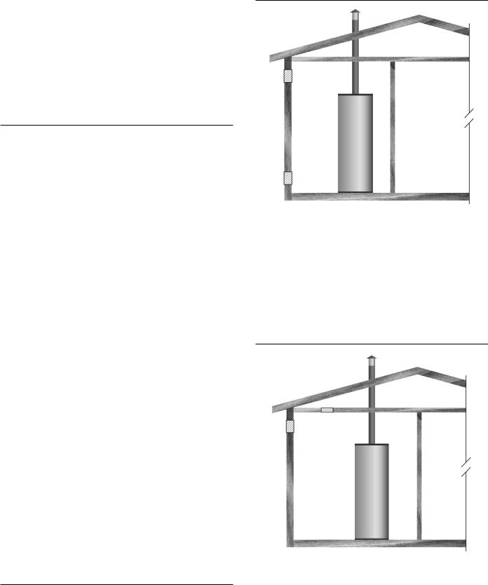
Outdoor Air Through Two Openings
FIGURE 4.
The confined space shall be provided with two permanent openings, one commencing within 12 inches (300 mm) of the top and one commencing within 12 inches (300 mm) of the bottom of the enclosure. The openings shall communicate directly with the outdoors. See Figure 4.
Each opening shall have a minimum free area of 1 square inch per 4,000 Btu/hr (550 mm2 per kW) of the aggregate input rating of all appliances installed in the enclosure. Each opening shall not be less than 100 square inches (645 cm2).
Outdoor Air Through One Opening
FIGURE 5.
Alternatively a single permanent opening, commencing within 12 inches (300 mm) of the top of the enclosure, shall be provided. See Figure 5. The water heater shall have clearances of at least 1 inch (25 mm) from the sides and back and 6 inches (l50 mm) from the front of the appliance. The opening shall directly communicate with the outdoors or shall communicate through a vertical or horizontal duct to the outdoors or spaces that freely communicate with the outdoors and shall have a minimum free area of the following:
12

1.1 square inch per 3000 Btu/hr (700 mm2 per kW) of the total input rating of all appliances located in the enclosure, and
2.Not less than the sum of the areas of all vent connectors in the space.
Outdoor Air Through Two Horizontal Ducts
FIGURE 6.
The confined space shall be provided with two permanent horizontal ducts, one commencing within 12 inches (300 mm) of the top and one commencing within 12 inches (300 mm) of the bottom of the enclosure. The horizontal ducts shall communicate directly with the outdoors. See Figure 6.
Each duct opening shall have a minimum free area of 1 square inch per 2,000 Btu/hr (1100 mm2 per kW) of the aggregate input rating of all appliances installed in the enclosure.
When ducts are used, they shall be of the same cross sectional area as the free area of the openings to which they connect. The minimum dimension of rectangular air ducts shall be not less than 3 inches.
Air From Other Indoor Spaces
FIGURE 7.
The confined space shall be provided with two permanent openings, one commencing within 12 inches (300 mm) of the top and one commencing within 12 inches (300 mm) of the bottom of the enclosure. See Figure 7.
Each opening shall communicate directly with an additional room(s) of sufficient volume so that the combined volume of all spaces meets the criteria for an Unconfined Space.
Each opening shall have a minimum free area of 1 square inch per 1,000 Btu/hr (1100 mm2 per kW) of the aggregate input rating of all appliances installed in the enclosure. Each opening shall not be less than 100 square inches (645 cm2).
13

installing the new water heater
CHEMICAL VAPOR CORROSION
CORROSION OF THE FLUEWAYS AND VENT SYSTEM MAY OCCUR IF AIR FOR COMBUSTION CONTAINS CERTAIN CHEMICAL VAPORS. SUCH CORROSION MAY RESULT IN FAILURE AND RISK OF ASPHYXIATION.
Spray can propellants, cleaning solvents, refrigerator and air conditioning refrigerants, swimming pool chemicals, calcium and sodium chloride (water softener salt), waxes, and process chemicals are typical compounds which are potentially corrosive.
Do not store products of this sort near the heater. Also, air which is brought in contact with the heater should not contain any of these chemicals. If necessary, uncontaminated air should be obtained from remote or outside sources. The limited warranty is voided when failure of water heater is due to a corrosive atmosphere. (See limited warranty for complete terms and conditions).
Water Piping
HOTTER WATER CAN SCALD:
Water heaters are intended to produce hot water. Water heated to a temperature which will satisfy space heating, clothes washing, dish washing, cleaning and other sanitizing needs can scald and permanently injure you upon contact. Some people are more likely to be permanently injured by hot water than others. These include the elderly, children, the physically or developmentally disabled. If anyone using hot water fits into one of these groups or if there is a local code or state law requiring a certain temperature water at the hot water tap, then you must take special precautions. In addition to using the lowest possible temperature setting that satisfies your hot water needs, a means such as a *mixing valve, should be used at the hot water taps used by these people or at the water heater, see Figure 6. Valves for reducing point of use temperature by mixing cold and hot water are also available:
Consult a Qualified Installer or Service Agency. Follow manufacturer’s instructions for installation of the valves. Before changing the factory setting on the thermostat, read the “Temperature Regulation” section in this manual.
This water heater shall not be connected to any heating systems or component(s) used with a non-potable water heating appliance.
All piping components connected to this unit for space heating applications shall be suitable for use with potable water.
Toxic chemicals, such as those used for boiler treatment shall not be introduced into this system.
When the system requires water for space heating at temperatures higher than required for domestic water purposes, a tempering valve must be installed. Please refer to Figure 8 for suggested piping arrangement.
Power Supply
The water heaters covered in this manual require a 120 VAC, 1Ø (single phase), 60Hz, 15 amp power supply and must also be electrically grounded in accordance with local codes or, in the absence of local codes, with the National Electrical Code, ANSI/ NFPA 70 or the Canadian Electrical Code, CSA C22.1.
Power Fluctuations and Electrical Noise
The water heater’s control system requires a source of stable clean electricity for proper operation. Connecting the water heater to a branch circuit that is subject to fluctuations in voltage level or electrical line noise such as EMI (electro magnetic interference) or RFI (radio frequency interference) may cause erratic control system operation and malfunction.
Ahigh quality power supply filter/suppressor such as the Kleen Line model SELF/T-10 Series SC-L or equivalent must be installed if the above conditions exist. Call the technical support phone number listed on the back cover of this manual for more information.
Note: Malfunctions caused by the power supply and the costs to install power supply filters are not covered under the limited warranty.
Dedicated Power Wiring and Breakers
Dedicated power supply wires, ground wiring and dedicated circuit breakers often prevent electrical line noise and should be considered when installing the water heater.
Polarity Sensitive
The control system on the water heaters covered in this manual is polarity sensitive; electronic flame sensing requires correct polarity. The control system is programmed to monitor the incoming power supply. If the Hot and Neutral wires in the 120 VAC power supply are reversed, the control system will declare a Fault condition and lock out, heating operation will be disabled until the power supply is correctly wired. The control system will display the “AC Reversed”
Fault message on the LCD.
14
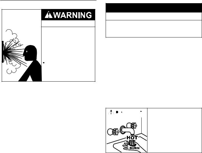
Mixing Valves
Water temperature over 125°F (52°C) can cause severe burns instantly resulting in severe injury or death.
Children, the elderly and the physically or mentally disabled are at highest risk for scald injury.
Feel water before bathing or showering.
Temperature limiting devices such as mixing valves must be installed when required by codes and to ensure safe temperatures at fixtures.
Water heated to a temperature which will satisfy clothes washing, dish washing, and other sanitizing needs can scald and cause permanent injury upon contact. Short repeated heating cycles caused by small hot water uses can cause temperatures at the point of use to exceed the water heater’s temperature setting by up to 20°F (11°C).
Some people are more likely to be permanently injured by hot water than others. These include the elderly, children, the infirm and the physically/mentally disabled. Table 1 shows the approximate time- to-burn relationship for normal adult skin. If anyone using hot water provided by the water heater being installed fits into one of these groups or if there is a local code or state law requiring a certain water temperature at the point of use, then special precautions must be taken.
In addition to using the lowest possible temperature setting that satisfies the demand of the application a Mixing Valve should be installed at the water heater (see Figure 8) or at the hot water taps to further reduce system water temperature.
Mixing valves are available at plumbing supply stores. Consult a Qualified Installer or Service Agency. Follow mixing valve manufacturer’s instructions for installation of the valves.
|
Table 1 |
|
|
|
|
Water Temperature |
Time to Produce 2nd & 3rd |
|
Degree Burns on Adult Skin |
||
|
||
180°F (82°C) |
Nearly instantaneous |
|
170°F (77°C) |
Nearly instantaneous |
|
160°F (71°C) |
About 1/2 second |
|
150°F (66°C) |
About 1-1/2 seconds |
|
140°F (60°C) |
Less than 5 seconds |
|
130°F (54°C) |
About 30 seconds |
|
120°F (49°C) |
More than 5 minutes |
|
Dishwashing Machines |
||
All dishwashing machines |
meeting the National Sanitation |
|
Foundation requirements are designed to operate with water flow pressures between 15 and 25 pounds per square inch (103 kPa and 173 kPa). Flow pressures above 25 pounds per square inch (173 kPa), or below 15 pounds per square inch (103 kPa), will result in improperly sanitized dishes. Where pressures are high, a water
pressure reducing or flow regulating control valve should be used in the 180°F (82°C) line to the dishwashing machine and should be adjusted to deliver water pressure between these limits.
|
|
HOT WATER |
|||
|
|
OUTLET |
|
|
|
|
|
|
|
||
|
|
|
|
|
|
|
|
|
12” TO 15” |
||
TEMPERED WATER |
(30-38 cm) |
|
|||
|
|
|
|||
|
OUTLET |
|
|
|
|
COLD |
|
|
CHECK |
||
WATER |
|
|
VALVE |
||
INLET |
|
|
MIXING |
||
|
|
CHECK |
|||
|
|
VALVE |
|||
|
|
VALVE |
|||
|
|
|
|
|
|
|
|
TO TANK |
|||
|
|
INLET |
|||
|
|
|
|
|
|
Figure 8.
The National Sanitation Foundation also recommends circulation of 180°F (82°C) water. Where this is done, the circulation should be very gentle so that it does not cause any unnecessary turbulence inside the water heater. The circulation should be just enough to provide 180°F (82°C) water at the point of take-off to the dishwashing machine.
Adjust flow by throttling a full port ball valve installed in the circulating line on the outlet side of the pump. Never throttle flow on the suction side of a pump.
Note: To comply with NSF Standard 5 installation requirements the bottom of the water heater must be sealed to the floor with a silicone based sealant or elevated 6 inches above the floor.
Space heating and potable water system
Your water heater is equipped with inlet/outlet connections for use in space heating applications (see Figure 9). If this water heater is to be used to supply both space heating and potable (drinking) water, the instructions listed below must be followed:
•Be sure to follow the manual(s) shipped with the air handler or other type heating system.
•This water heater is not to be used as a replacement for an existing boiler installation.
•Do not use with piping that has been treated with chromates, boiler seal or other chemicals and do not add any chemicals to the water heater piping
•If the space heating system requires water temperatures in excess of 120°F, a tempering valve (provided) must be installed per the manufacturer’s instructions in the potable hot water supply to limit the risk of scald injury.
•Pumps, valves, piping and fi ttings must be compatible with potable water.
•A properly installed flow control valve is required to prevent thermosiphoning. Thermosiphoning is the result of a continuous flow of water through the air handler circuit during the off cycle. Weeping (blow off) of the temperature and pressure relief valve (T & P) or higher than normal water temperatures are the fi rst signs of thermosiphoning.
15

•The hot water line from the water heater should be vertical past any tempering valve or supply line to the heating system to remove air bubbles from the system.
•Do not connect the water heater to any system or components previously used with non-potable water heating appliances when used to supply potable water.
Figure 10.
Figure 9.
CLOSED WATER SYSTEMS
Water supply systems may, because of code requirements or such conditions as high line pressure, among others, have installed devices such as pressure reducing valves, check valves, and back flow preventers. Devices such as these cause the water system to be a closed system.
THERMAL EXPANSION
Aswaterisheated,itexpands(thermalexpansion).Inaclosedsystem the volume of water will grow when it is heated. As the volume of water grows there will be a corresponding increase in water pressure due to thermal expansion. Thermal expansion can cause premature tank failure (leakage). This type of failure is not covered under the limited warranty. Thermal expansion can also cause intermittent temperature-pressure relief valve operation: water discharged from the valve due to excessive pressure build up. This condition is not covered under the limited warranty. The temperature-pressure relief valve is not intended for the constant relief of thermal expansion.
A properly sized thermal expansion tank should be installed on all closed systems to control the harmful effects of thermal expansion.
NOTE: To protect against untimely corrosion of hot and cold water fittings, it is strongly recommended that di-electric unions or couplings be installed on this water heater when connected to copper pipe, see Figure 10 also.
Figures 9 and 10 show the typical attachment of the water piping to the water heater. The water heater is equipped with 3/4 inch NPT water connections.
NOTE: If using copper tubing, solder tubing to an adapter before attaching the adapter to the water heater connections. Do not solder the water lines directly to the water heater connections. It will harm the dip tube and damage the tank.
T & P Valve and Pipe Insulation (if supplied)
Remove insulation for T & P valve and pipe connections from carton.
Figure 11.
16
Fit pipe insulation over the incoming cold water line and the hot water line. Make sure that the insulation is against the top cover of the heater.Fit T & P valve insulation over valve. Make sure that the insulation does not interfere with the lever of the T & P valve.
Secure all insulation using tape.
Temperature-Pressure Relief Valve
Explosion Hazard
 Temperature-Pressure Relief Valve must comply with ANSI Z21.22CSA 4.4 and ASME code.
 Properly sized temperaturepressure relief valve must be installed in opening provided.
Can result in overheating and excessive tank pressure.
 Can cause serious injury or death.
This water heater is provided with a properly rated/sized and certified combination Temperature-Pressure Relief Valve (T&P valve) by the manufacturer. The valve is certified by a nationally recognized testing laboratory that maintains periodic inspection of production of listed equipment of materials as meeting the requirements for Relief Valves for Hot Water Supply Systems, ANSI Z21.22 • CSA 4.4, and the code requirements of ASME.
If replaced, the new T&P valve must meet the requirements of local codes, but not less than a combination TemperaturePressure Relief Valve rated/sized and certified as indicated in the above paragraph. The new valve must be marked with a maximum set pressure not to exceed the marked hydrostatic working pressure of the water heater (150 psi = 1,035 kPa) and a discharge capacity not less than the water heater Btu/hr or kW input rate as shown on the water heater’s model rating plate.
Note: In addition to the factory installed Temperature-Pressure Relief Valve on the water heater, each remote storage tank that may be installed and piped to a water heating appliance must also have its own properly sized, rated and approved
Temperature-Pressure Relief Valve installed. Call the toll free technical support phone number listed on the back cover of this manual for technical assistance in sizing a Temperature-
Pressure Relief Valve for remote storage tanks.
For safe operation of the water heater, the Temperature-
Pressure Relief Valve must not be removed from its designated opening nor plugged. The Temperature-Pressure Relief Valve must be installed directly into the fitting of the water heater designed for the relief valve. Install discharge piping so that any discharge will exit the pipe within 6 inches (15.2 cm) above an adequate floor drain, or external to the building. In cold climates it is recommended that it be terminated at an adequate drain inside the building. Be certain that no contact is made with any live electrical part. The discharge opening must not be blocked or reduced in size under any circumstances. Excessive length, over 30 feet (9.14 m), or use of more than four elbows can cause restriction and reduce the discharge capacity of the valve.
No valve or other obstruction is to be placed between the Temperature-Pressure Relief Valve and the tank. Do not connect discharge piping directly to the drain unless a 6” (15.2 cm) air gap is provided.To prevent bodily injury, hazard to life, or property damage, the relief valve must be allowed to discharge water in adequate quantities should circumstances demand. If the discharge pipe is not connected to a drain or other suitable means, the water flow may cause property damage.
CAUTION
Water Damage Hazard
•Temperature-Pressure Relief Valve discharge pipe must terminate at adequate drain.
T&P Valve Discharge Pipe Requirements:
•Shall not be smaller in size than the outlet pipe size of the valve, or have any reducing couplings or other restrictions.
•Shall not be plugged or blocked.
•Shall not be exposed to freezing temperatures.
•Shall be of material listed for hot water distribution.
•Shall be installed so as to allow complete drainage of both the Temperature-Pressure Relief Valve and the discharge pipe.
•Must terminate a maximum of six inches above a floor drain or external to the building. In cold climates, it is recommended that the discharge pipe be terminated at an adequate drain inside the building.
•Shall not have any valve or other obstruction between the relief valve and the drain.

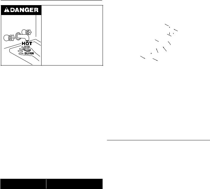
 Burn hazard.
 Hot water discharge.
 Keep clear of TemperaturePressure Relief Valve discharge outlet.
The Temperature-Pressure Relief Valve must be manually operated at least twice a year. Caution should be taken to ensure that (1) no one is in front of or around the outlet of the Temperature-Pressure Relief Valve discharge line, and (2) the water manually discharged will not cause any bodily injury or property damage because the water may be extremely hot. If after manually operating the valve, it fails to completely reset and continues to release water, immediately close the cold water inlet to the water heater, follow the draining instructions in this manual, and replace the Temperature-Pressure Relief Valve with a properly rated/sized new one.
Note: The purpose of a Temperature-Pressure Relief Valve is to prevent excessive temperatures and pressures in the storage tank. The T&P valve is not intended for the constant relief of thermal expansion.Aproperly sized thermal expansion tank must be installed on all closed systems to control thermal expansion, see Closed
Water Systems and Thermal Expansion on pages 15 and 16.
If you do not understand these instructions or have any questions regarding the Temperature-Pressure Relief Valve call the toll free number listed on the back cover of this manual for technical assistance.
17

gas piping
Make sure gas supplied is same type listed on model rating plate.
The inlet gas pressure must not exceed 14 inch water column (3.5 kPa) for natural and propane gas (L.P.). The minimum inlet gas pressure shown on rating plate is that which will permit firing at rated input.
Allgaspipingmustcomplywithlocalcodesandordinancesorwiththe National Fuel Gas Code (ANSI Z223.1/ NFPA-54) or the Natural Gas and Propane Installation Code (CAN/CSA B149.1) whichever applies. Copper or brass tubing and fittings (except tin lined copper tubing) shall not be used.
If the gas control valve is subjected to pressures exceeding 1/2 psi (3.5 kPa), the damage to the gas control valve could result in a fire or explosion from leaking gas.
If the main gas line Shut-off serving all gas appliances is used, also turn “off” the gas at each appliance. Leave all gas appliances shut “off” until the water heater installation is complete.
A gas line of sufficient size must be run to the water heater. Consult the current edition of National Fuel Gas Code (ANSI Z223.1/NFPA54) or the Natural Gas and Propane Installation Code (CAN/CSA B149.1) and your gas supplier concerning pipe size.
There must be:
•A readily accessible manual shut off valve in the gas supply line serving the water heater, and
•A drip leg (sediment trap) ahead of the gas control valve to help prevent dirt and foreign materials from entering the gas control valve.
•A flexible gas connector or a ground joint union between the shut off valve and control valve to permit servicing of the unit.
Be sure to check all the gas piping for leaks before lighting the water heater. Use a soapy water solution, not a match or open flame. Rinse off soapy solution and wipe dry.
CONDENSATE Piping
This water heater is a condensing unit and requires a drain to be located in close proximity to allow the condensate to drain safely. The condensate drains from the unit at the exhaust tee located at the bottom of the unit (see figure 12). Condensate from this water heater is mildly acidic. Please note that some local codes require that condensate is treated by using a pH neutralizing filter prior to disposal.
Caution must be used to ensure that the drain is free and clear of debris and will not allow backflow through the condensate hose.
Consideration must be given to avoid freezing of the condensate lines which could result in excessive build up of condensate inside the water heater. Waterproof heat tape may be required to prevent freezing of the condensate lines. Please ensure that the outlet of the condensate drain does not create a slippery condition which could lead to personal injury.
CONDENSATION WARNING: THIS WATER HEATER IS A
CONDENSING UNIT AND REQUIRES A DRAIN TO BE LOCATED IN CLOSE PROXIMITY TO ALLOW CONDENSATE TO DRAIN SAFELY. THE CONDENSATE DRAINS FROM UNIT AT THE
EXHAUST ELBOW LOCATED AT BOTTOM OF UNIT. NOTE:
IT IS IMPORTANT THAT THE CONDENSATE HOSE NOT BE ELEVATED ABOVE THE EXHAUST ELBOW, SEE FIGURE 12. CONDENSATE BUILD-UP WILL BLOCK THE EXHAUST OUTLET, WHICH WILL CAUSE IMPROPER OPERATION.
Figure 12
The condensate drain line must be routed to a suitable drain. If no floor drain is available or the drain is above the level of the condensate line, install a condensate pump that is resistant to the acidic condensate. These pumps are available from local distributors. If the pump is not resistant to acidic water, a condensate neutralizer must be used ahead of the pump. When installing the drain line, note the following:
•Plastic pipe or tubing must be used to connect the condensate drain to a suitable drain or condensate pump. Do not use copper tubing, iron, or steel pipe for the condensate drain line.
•Condensate drain lines should be installed in conditioned areas only. Drain lines installed in areas that are subject to freezing temperatures should be wrapped with a nationally recognized/listed heat tape and/or approved insulation for freeze protection. Install per manufacturer’s instructions.
•Do not common drain with the temperature and pressure relief valve or the condensate line from an air conditioner evaporator coil.
•Slope the condensate drain toward the inside floor drain or condensate pump.
•The condensate drain line and connection to the drain piping must comply with all local codes.
18
 Loading...