


 Loading...
COMMERCIAL / RESIDENTIAL GAS WATER HEATERS
FOR MODELS:
SERVICE HANDBOOK
ULTRA HIGH EFFICIENCY POWER VENT / POWER DIRECT VENT
•BTX-100
•GDHE-50
PRINTED 0308 |
1 |
198142-000 |
|
|
ULTRA HIGH EFFICIENCY
POWER VENT/POWER DIRECT VENT
SERVICE MANUAL
Technical Literature Department ©2008
TABLE OF CONTENTS
INTRODUCTION ............................................................ |
2 |
Qualifications ............................................................ |
2 |
Service Warning ....................................................... |
2 |
Important Service Reminder..................................... |
2 |
Instruction Manual .................................................... |
3 |
Tools Required.......................................................... |
3 |
INSTALLATION CONSIDERATIONS ............................. |
4 |
Closed Water Systems ............................................. |
4 |
Thermal Expansion................................................... |
4 |
Air Requirements...................................................... |
5 |
Contaminated Air...................................................... |
5 |
Venting...................................................................... |
6 |
Electrical Requirements............................................ |
8 |
OPERATION & SERVICE............................................... |
9 |
How it works ............................................................. |
9 |
Blower..................................................................... |
10 |
Burner...................................................................... |
11 |
Venturi .................................................................... |
14 |
Gas Valve ............................................................... |
15 |
Gas Pressure Testing ............................................. |
16 |
Air Pressure Switches ............................................ |
18 |
Air Pressure Switch Operation ............................... |
20 |
Air Pressure Switch Testing.................................... |
21 |
Flame Sensing Test ................................................ |
24 |
Igniter Current Test ................................................. |
25 |
CONTROL SYSTEM..................................................... |
26 |
Introduction............................................................. |
26 |
UIM ......................................................................... |
27 |
Discreet Menu - Contact Information ............... |
28 |
Operating Set Point Adjustment ............................. |
32 |
Control System Menus ........................................... |
33 |
CCB ........................................................................ |
35 |
Socket Identification......................................... |
36 |
Wiring Diagram....................................................... |
39 |
Sequence of Operation........................................... |
40 |
TROUBLESHOOTING................................................... |
|
41 |
Rough Start - Rough Operation ............ |
13 and 41 |
|
Heater Status Menu .......................................... |
|
33 |
Things to Check Before Servicing .................... |
|
41 |
Reset Procedure............................................... |
|
41 |
Control System Unresponsive................................. |
|
42 |
Blank Display .................................................... |
|
42 |
UIM Inoperable ................................................. |
|
42 |
Fault Messages....................................................... |
|
43 |
AC Reversed .................................................... |
|
43 |
Upper Probe Open............................................ |
|
43 |
Upper Probe Short............................................ |
|
44 |
Flame Probe Short............................................ |
|
44 |
Flame Detect Error ........................................... |
|
45 |
Energy Cut Out (ECO)...................................... |
|
45 |
Blocked Inlet ..................................................... |
|
46 |
Blocked Exhaust Vent....................................... |
|
47 |
Blower Prover Failure ....................................... |
|
47 |
Blower Prover Open - Blower Not Running ...... |
48 |
|
Blower Prover Open - Blower Is Running ......... |
48 |
|
Low Igniter Current ........................................... |
|
49 |
Ignition Failure .................................................. |
|
50 |
Gas Valve Failure ............................................. |
|
52 |
Communication Failure..................................... |
|
52 |

ULTRA HIGH EFFICIENCY POWER VENT/POWER DIRECT VENT - SERVICE MANUAL
INTRODUCTION
This Service Manual is designed to be an aid in servicing and troubleshooting the 96% thermally efficient, 50 gallon, 100,000 Btu/hr residential and light duty commercial power vent - power direct vent model water heaters listed on the cover of this manual.The instructions, illustrations and procedures contained in this manual are used to verify proper operation and to diagnose and repair common service problems.
This manual does not replace or supersede the Instruction Manual that came with the water heater. Always refer to the Instruction Manual that came with the water heater for complete installation instructions. If the Instruction Manual is not available copies can be obtained from the manufacturers web site or by calling the technical support phone number shown on the water heater labeling.
QUALIFICATIONS - QUALIFIED SERVICE AGENT
Servicing the products referenced in this manual requires the ability (in the field involved) equivalent to that of a Qualified Service Agent as defined by the American National
Standards Institute (ANSI) below. Installation skills such as plumbing, air supply, venting, gas supply, electrical supply are required in addition to diagnostic and electrical testing skills.
ANSI Z223.1 2006 Sec. 3.3.83: “Qualified Agency” - “Any individual, firm, corporation or company that either in person or through a representative is engaged in and is responsible for (a) the installation, testing or replacement of gas piping or (b) the connection, installation, testing, repair or servicing of appliances and equipment; that is experienced in such work; that is familiar with all precautions required; and that has complied with all the requirements of the authority having jurisdiction.”
SERVICE WARNING
If you are not qualified (as defined by ANSI above) and licensed or certified as required by the authority having jurisdiction to perform a given task do not attempt to perform any of the service or installation procedures described in this manual. If you do not understand the instructions given in this manual or do not feel confident in your abilities to perform a given task do not attempt to perform any procedures outlined in this manual.
IMPORTANT SERVICE REMINDER
When performing any troubleshooting step outlined in this Service Manual always consider the wiring and connectors between components. Perform a close visual inspection of all wiring and connectors to and from a given component before replacement. Ensure wires were stripped before being crimped in a wire connector, ensure wires are crimped tightly in their connectors, ensure connection pins in sockets and plugs are not damaged or worn, ensure plugs and sockets are mating properly and providing good contact.
Failure to perform this critical step or failing to perform this step thoroughly often results in needless down time, unnecessary parts replacement, and customer dissatisfaction.
Technical Literature Department |
2 of 52 |
Ashland City, TN © 2008 |
Servicing should only be performed by a Qualified Service Agent |
|
|

ULTRA HIGH EFFICIENCY POWER VENT/POWER DIRECT VENT - SERVICE MANUAL
INSTRUCTION MANUAL
Have a copy of the Instruction Manual that came with the water heater on hand for the correct model water heater you are working with before servicing.
Installation information given in this Service Manual is not a complete installation instruction. Installation information covered in this Service Manual has a limited focus as it applies to servicing. This Service Manual does not replace or supersede the Instruction Manual that came with the water heater. Always refer to the Instruction Manual that came with the water heater for complete installation instructions.
If the Instruction Manual is not on hand copies can be obtained from the manufacturers web site or by calling the technical support phone number shown on the water heater labeling.
TOOLS REQUIRED
•Instruction Manual that came with the water heater.
•All tools common to installation and service of commercial water heaters such as hand tools, torch, pipe wrenches etc.
•Long (8-10”) T handle SAE hex (allen key) wrenches including 5/32”, 1/8” and 1/4” - for blower, burner, and gas valve removal and installation.
•Two digital manometers range -20.00 to +20.00" W.C., resolution - 0.01" W.C.
Recommend UEI model EM200 or equivalent. Required to test performance of air pressure switches. Also used to measure low pressure supply gas and manifold gas pressure.
•Digital Multi Meter DMM; recommend Fieldpiece HS36, Fluke 187, UEI DL289 or equivalent capable of measuring:
•AC/DC Voltage
•AC Frequency (Hz)
•Ohms
•DC micro amps µA (flame sensing current)
•AC amp meterrecommend UEI model DL289 or equivalent.
•120 VAC household outlet tester (see Service Notes Electrical page 8)
Technical Literature Department |
3 of 52 |
Ashland City, TN © 2008 |
Servicing should only be performed by a Qualified Service Agent |
|
|

ULTRA HIGH EFFICIENCY POWER VENT/POWER DIRECT VENT - SERVICE MANUAL
INSTALLATION CONSIDERATIONS
INSTRUCTION MANUAL
Installation information given in this Service Manual is not a complete installation instruction. Installation information covered in this Service Manual has a limited focus as it applies to servicing. This Service Manual does not replace or supersede the Instruction Manual that came with the water heater. Always refer to the Instruction Manual that came with the water heater for complete installation instructions.
If the instruction Manual that came with the water heater is not on hand copies can be obtained from the manufacturers web site or by calling the technical support phone number shown on the water heater labeling.
CLOSED WATER SYSTEMS
Water supply systems may, because of code requirements or such conditions as high line pressure, among others, have installed devices such as pressure reducing valves, check valves, and back flow preventers. Devices such as these cause the water system to be a closed system.
Virtually all commercial and most residential water supply systems are closed systems today. Closed water systems will experience thermal expansion which, if not controlled with a properly installed and sized thermal expansion tank, can cause premature failure (leakage) of the water heater. Water heater failure (leakage) on closed systems where there is not a thermal expansion tank installed is not covered under the limited warranty.
THERMAL EXPANSION
As water is heated, it expands (thermal expansion). In a closed system the volume of water will grow when it is heated. As the volume of water grows there will be a corresponding
increase in water pressure due to thermal expansion. Thermal expansion can cause premature tank failure (leakage). This type of failure is not covered under the limited warranty. Thermal expansion can also cause intermittent temperature-pressure relief valve
operation: water discharged from the valve due to excessive pressure build up. This condition is not covered under the limited warranty. The temperature-pressure relief
valve is not intended for the constant relief of thermal expansion.
A properly sized thermal expansion tank should be installed on all closed systems to control the harmful effects of thermal expansion.
Technical Literature Department |
4 of 52 |
Ashland City, TN © 2008 |
Servicing should only be performed by a Qualified Service Agent |
|
|

ULTRA HIGH EFFICIENCY POWER VENT/POWER DIRECT VENT - SERVICE MANUAL
AIR REQUIREMENTS
Carefully review the requirements for combustion and ventilation air in the Instruction
Manual that came with the water heater. Failure to meet these requirements when the water heater is installed or overlooking their importance when servicing the water heater often results in needless down time, unnecessary parts replacement, and customer dissatisfaction. If the Instruction Manual is not on hand copies can be obtained from the manufacturers web site or by calling the technical support phone number shown on the water heater labeling.
An inadequate supply of air for combustion and ventilation often causes operational problems. A lack of combustion and ventilation air can create a negative ambient air pressure in the installed space which can lead to improper combustion and operational problems with air pressure switches.
CONTAMINATED AIR
Combustion air that is contaminated can greatly diminish the life span of the water heater and water heater components such as hot surface igniters and burners. Propellants of aerosol sprays, beauty shop supplies, water softener chemicals and chemicals used in dry cleaning processes that are present in the combustion, ventilation or ambient air can cause such damage.
Vapors from volatile compounds such as solvents, cleaners, chlorine based chemicals and refrigerants in addition to being highly flammable in many cases, can also react to form highly corrosive substances such as hydrochloric acid inside the water heater’s combustion chamber. The results can be hazardous and cause product failure.
If this water heater will be installed in beauty shops, barber shops or laundries with dry cleaning equipment, it is imperative the water heater be installed as a Direct Vent appliance so that air for combustion is derived directly from the outside atmosphere through a sealed intake air pipe. See the Installation of Vent System section in the Instruction Manual that came with the water heater for more information on Direct Vent installations.
Technical Literature Department |
5 of 52 |
Ashland City, TN © 2008 |
Servicing should only be performed by a Qualified Service Agent |
|
|

ULTRA HIGH EFFICIENCY POWER VENT/POWER DIRECT VENT - SERVICE MANUAL
VENTING
The venting information presented in this Service Manual is not a complete venting installation instruction. Refer to the Instruction Manual that came with the water heater for complete installation instructions.
The water heater covered in this Service Manual may be installed as a conventionally vented water heater or as a direct vent water heater. Conventional vent installations use room air for combustion. There will be one “vent” pipe installed on a conventional vent installation. Direct vent installations derive all air for combustion from the outdoor atmosphere through a second “intake air” pipe. There will be two pipes (vent and intake air) installed on a direct vent installation.
The vent and intake air piping (direct vent installations) may not be combined with any other appliances under any conditions.
Maximum Equivalent Length Requirements
The vent and intake air pipe (direct vent installations) for the water heater covered in this Service Manual can be installed using 2, 3, or 4 inch pipe depending on the overall “equivalent” length of each pipe; see Table 1 on page 7.
The vent and intake air terminations do not factor into the overall equivalent feet calculations.
The vent and intake air connection fittings on the water heater do not factor into the overall equivalent feet calculations.
Additional 2 or 3 inch 90° elbows installed are equivalent to 5 linear feet of pipe. Additional 4 inch 90° elbows are equivalent to 8 linear feet of pipe. 45° elbows will count for half the equivalent length a 90° elbow does.
2” 3”
3” 
4” 
=5 linear feet of pipe
=5 linear feet of pipe
=8 linear feet of pipe
Overall equivalent lengths are determined by adding the total length of pipe installed to the accumulated total equivalent length of all the additional elbows factored in.
The maximum equivalent lengths given in the Instruction Manual that came with the water heater and shown in Table 1 (page 7) are for the vent pipe AND for the intake air pipe. IE: A
2 inch vent pipe can be up to 20 equivalent feet with one 90° elbow. On a direct vent installation the 2 inch intake air pipe can also be up to 20 equivalent feet with one 90° elbow.
Carefully review the venting installation instructions and maximum equivalent length requirements for the vent and intake air piping. Ensure the vent system has been installed per Instruction Manual requirements.
Technical Literature Department |
6 of 52 |
Ashland City, TN © 2008 |
Servicing should only be performed by a Qualified Service Agent |
|
|

ULTRA HIGH EFFICIENCY POWER VENT/POWER DIRECT VENT - SERVICE MANUAL
VENTING (CONT)
Pipe Size Requirements
Ensure the correct size pipe has been used for the overall equivalent length of the vent and intake air piping installed. Longer equivalent lengths require larger pipe sizes, see Table 1.
Maximum Elbow Requirements
Three and four inch vent and intake air pipe installations allow a maximum of 6 - 90° elbows in the vent pipe AND a maximum 6 - 90°elbows in the intake air pipe. Two inch installations allow a maximum of 3 - 90° elbows in the vent pipe AND a maximum 3 - 90° elbows the intake air pipe.
Table 1
NUMBER |
2” MAXIMUM PIPE |
3” MAXIMUM PIPE |
4” MAXIMUM PIPE |
|
90° ELBOWS |
LENGTH FEET (METERS) |
LENGTH FEET (METERS) |
LENGTH FEET (METERS) |
|
|
|
|
|
|
1 |
20 (6.1) |
60 (18.3) |
120 (36.6) |
|
2 |
15 (4.6) |
55 (16.8) |
112 (34.1) |
|
3 |
10 (3.0) |
50 (15.2) |
104 (31.7) |
|
4 |
4 elbows not allowed in 2” pipe |
45 (13.7) |
96 (29.3) |
|
(use larger pipe size) |
||||
|
|
|
||
|
|
|
|
|
5 |
5 elbows not allowed in 2” pipe |
40 (12.2) |
88 (26.8) |
|
(use larger pipe size) |
||||
|
|
|
||
|
|
|
|
|
6 |
6 elbows not allowed in 2” pipe |
35 (10.7) |
80 (24.3) |
|
(use larger pipe size) |
||||
|
|
|
||
|
|
|
|
Service Notes - Venting
Remove all plastic debris from the edges of intake air pipe sections after cutting on direct vent installations. Plastic debris left on intake air pipe sections can collect inside and clog the burner and lead to rough operation and/or ignition failure. See Service Notes page 11.
Using a smaller pipe size than required for a given length or installing more elbows on the
vent pipe can cause the water heater’s control system to declare a fault condition, lock out and display the “Blocked Exhaust” fault message on the UIM display (see page 27).
Overlooking the same requirements for the intake air pipe on direct vent installations or failing to remove the screen from the intake air connection when direct venting can cause
the water heater’s control system to declare a fault condition, lock out and display the
“Blocked Inlet” fault message on the UIM display (see page 27).
Remove This Screen
For Direct Vent
Installations
The screen inside the intake air connection is meant to keep larger debris from entering the blower when the water heater is installed conventionally; using room air for combustion.
When the water heater is installed in a direct vent configuration the screen inside the intake air connection on the water heater
must be removed. If left in place it will become clogged over time and lead to “Blocked Inlet” lock out conditions.
The screen on the intake air termination will keep larger debris from entering the blower on direct vent installations.
Technical Literature Department |
7 of 52 |
Ashland City, TN © 2008 |
Servicing should only be performed by a Qualified Service Agent |
|
|

ULTRA HIGH EFFICIENCY POWER VENT/POWER DIRECT VENT - SERVICE MANUAL
ELECTRICAL REQUIREMENTS
The water heater covered by this Service Manual must be grounded in accordance with the local codes, or in the absence of local codes: the National Electrical Code (NFPA 70) or the Canadian Electrical Code (C22.1).
The water heater covered by this Service Manual requires a 120 VAC 1Ø (single phase) power supply. It is factory equipped with a standard 3 prong appliance cord that plugs into a standard 120 VAC wall outlet. 5.2 FLA (full load amps) approximate.
As shown in the illustration below there should be 120 VAC present between the power supply hot and ground wires. 120 VAC should also present between the hot and neutral wires. There should be 0 VAC present between the neutral and ground wires.
Correct wiring for a standard 120 VAC wall outlet is also shown in the Illustration below. Note the orientation of the ground connect is at the bottom. Reversed polarity is when the hot and neutral wires are connected opposite from what is shown here.
Service Notes - Electrical
This water heater is a polarity sensitive appliance and will not operate if the power supply
polarity is reversed. If the polarity of the power supply is reversed the water heater’s control system will declare a fault condition and display “AC Reversed” on the UIM display.
The water heater’s burner must be grounded for flame sensing current to be established and
verify ignition. If the burner is not grounded the water heater’s control system will declare a fault condition and display “Ignition Failure” on the UIM display after 3 failed ignition trials.
Also shown is an outlet tester that will quickly determine if the plug is wired correctly. These testers will also diagnose reversed polarity, open ground and open neutral wire problems. Outlet testers are inexpensive and simple to use. They are available at most hardware stores and home centers.
120 VAC 1Ø Power Supply |
Correctly Wired Outlet |
||||||||||
|
|
|
|
|
120 VAC 1Ø |
||||||
|
|
|
|
|
|||||||
HOT |
NEUTRAL |
GROUND |
|
|
|
Wall Outlet |
|||||
|
|
|
|
|
|
|
|
||||
|
|
|
Neutral |
|
|
|
|
|
|
|
Hot |
Ground
Outlet Tester
120 volts |
|
|
0 volts |
|
|
||||
|
|
|
|
|
|
|
|
|
|
120 volts
Technical Literature Department |
8 of 52 |
Ashland City, TN © 2008 |
Servicing should only be performed by a Qualified Service Agent |
|
|

ULTRA HIGH EFFICIENCY POWER VENT/POWER DIRECT VENT - SERVICE MANUAL
OPERATION & SERVICE
HOW IT WORKS
This section of the Service Manual will cover operation, common service procedures and water heater construction. The water heater covered in this Service Manual has a helical coil shaped heat exchanger that is submerged in the storage tank. The water heater uses a top mounted down fired radial burner. This is a forced draft burner; hot burning gases are forced through the heat exchanger under pressure and exit through the exhaust/vent connection located at the bottom of the water heater.
BLOWER/BURNER
GAS VALVE
ASSEMBLY
Starting at the top combustion air and fuel gas are drawn in by the blower (page 10) and Venturi (page 14).
The hot burning gases exit the radial burner (page 11) and are forced through the coil shaped heat exchanger.
Flue gases spiral through the heat exchanger and exit the water heater through the exhaust/vent connection at the bottom.
EXTERNAL VIEW
 COMBUSTION AIR INTAKE CONNECTION
INTERNAL VIEW |
COMBUSTION |
|
AIR INTAKE |
|
CONNECTION |
HELICAL
SHAPED
HEAT EXHNGER
EXHAUST/VENT |
EXHAUST/VENT |
CONNECTION |
|
CONNECTION |
|
Technical Literature Department |
9 of 52 |
Ashland City, TN © 2008 |
Servicing should only be performed by a Qualified Service Agent
ULTRA HIGH EFFICIENCY POWER VENT/POWER DIRECT VENT - SERVICE MANUAL
BLOWER
The blower is an assembly consisting of the blower housing, motor and an integrated VFD (variable frequency drive). Blower operation is controlled by the CCB (central control board - page 35). The CCB sends 120 VAC to the Blower/VFD assembly high voltage 3 pin
socket. The CCB also sends a PWM (pulse width modulation) signal to the Blower/VFD assembly low voltage 5 pin socket.
The PWM signal is a digital instruction sent to the VFD instructing it to start, stop, and control blower speed. The VFD powers the blower motor directly. The VFD also varies the frequency (Hz) of the power it sends to the blower motor which in turn controls blower speed. Higher frequency = faster blower speed, lower frequency = slower blower speed.
Service Notes - Blower
The PWM signal plug MUST remain plugged in to the 5 pin socket on the blower assembly at all times. Removing this plug will cause the blower to accelerate and the Btu/hr input of the water heater to increase to a much higher rate. This may cause damage to the water heater.
Blower Housing |
Low Voltage PWM 5 Pin Socket |
Blower Motor / VFD Assembly |
|
High Voltage 120 VAC 3 Pin Socket
Technical Literature Department |
10 of 52 |
Ashland City, TN © 2008 |
Servicing should only be performed by a Qualified Service Agent |
|
|
ULTRA HIGH EFFICIENCY POWER VENT/POWER DIRECT VENT - SERVICE MANUAL
BURNER
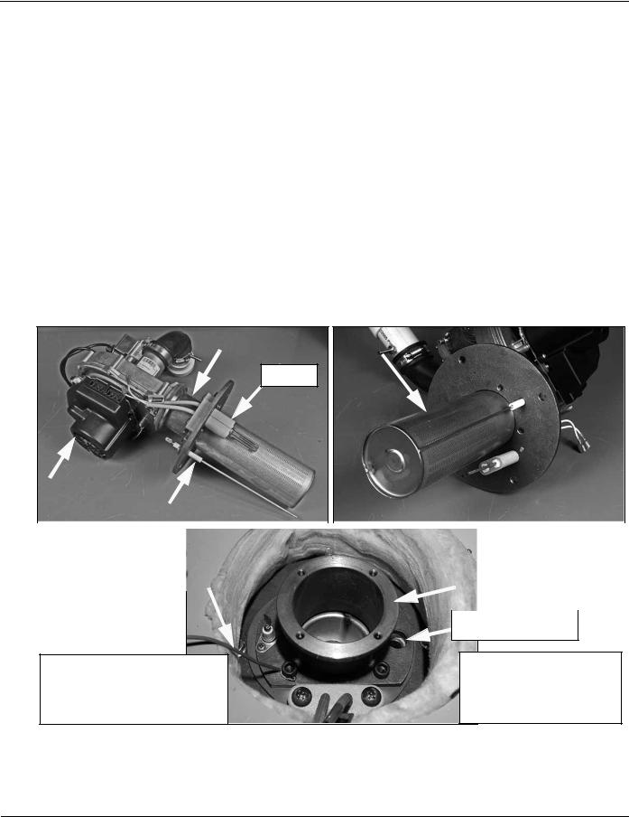
The images below show a complete blower/burner assembly removed along with a top view of the water heater with the blower removed.
Service Notes - Burner (Flame Sensor)
The burner installed in the water heater is a radial fire burner. Radial fire burners can trap debris that enter the blower. Be sure to thoroughly clean the edges of intake air pipe sections after cutting during the installation. If this is not done plastic shavings can collect inside the burner and lead to rough operation and/or ignition failure.
The burner should be removed and inspected whenever servicing for rough operation or ignition failure problems. Burner removal requires removal of the blower. Blower removal requires 8-10” long T handle 1/8” hex (allen) wrench.
The flame sensor will accumulate corrosion (rust etc) over time. This will reduce flame sensing current. This is the most common cause of “Ignition Failure” lock outs. The flame
sensor should cleaned when servicing due to ignition failure and as a routine maintenance procedure. Fine grade steel wool is recommended for cleaning the flame sensor; do not use coarse abrasives such as sand paper.
|
|
|
Blower Adapter |
|
Radial Fire Burner |
|
|
|
Igniter |
|
Blower VFD |
|
|
|
|
|
|
|
|
|
|
|
|
|
|
Assembly |
|
Flame Sensor |
|
|
|
|
|
|
|
||||
|
|
|
|
|
|
|
|
|
|
|
|
|
|
|
|
|
|
|
|
|
|
|
|
|
|
|
|
|
|
|
|
|
|
|
|
|
|
|
|
|
|
|
|
|
|
|
|
|
|
|
|
|
|
|
|
|
|||
|
|
|
|
|
|
Top View Water Heater - Blower Removed |
|
|
|
|||||
|
|
|
|
|
|
|
|
|
|
|
|
|||
|
|
|
|
|
|
|
|
|
|
|
|
|
|
|
|
|
Burner Ground Wire |
|
|
|
Blower Adapter |
|
|||||||
|
|
|
|
|
|
|
|
|
|
|
|
|
|
|
|
|
|
|
|
|
|
|
|
|
|
|
|
|
|
Burner must be grounded for flame sensing current to be established. See Service Notes - Electrical page 8
Burner View Port
Blower removal requires 8 -10” long T handle 1/8” hex (allen) wrench.
Technical Literature Department |
11 of 52 |
Ashland City, TN © 2008 |
Servicing should only be performed by a Qualified Service Agent |
|
|
ULTRA HIGH EFFICIENCY POWER VENT/POWER DIRECT VENT - SERVICE MANUAL
BURNER (CONT)
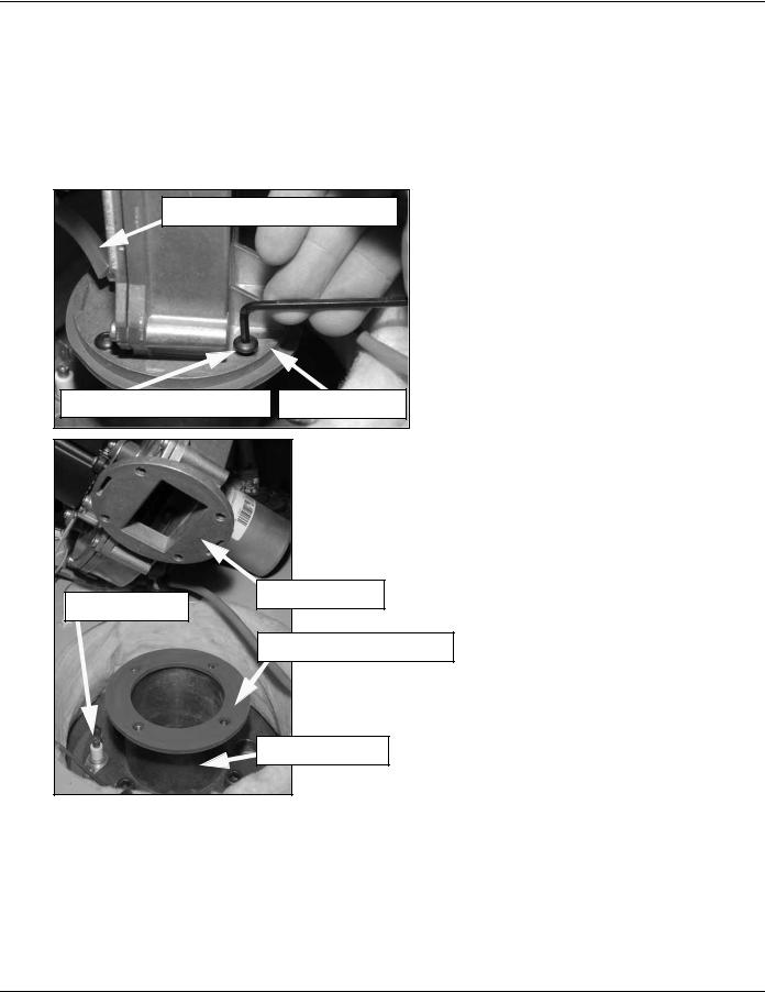
Burner & Blower Removal
The burner should be removed and inspected whenever service is being performed for rough operation or ignition failure. Radial fire burners like the one used on this water heater can trap debris, see Service Notes - Venting on page 7.
The following images illustrate the burner removal procedure. Long T handle hex wrenches (8-10”) will save considerable time when removing/installing the burner & blower.
Blower Prover Sensing Tube |
|
1/8” Hex Machine Screws |
Blower Flange |
BLOWER/BURNER REMOVAL PROCEDURE
1Ensure power to the water heater is turned off.
2The blower assembly must be removed first.
3Disconnect the two wiring plugs from the blower assembly sockets (see Service Notes - Blower page 10).
4Disconnect the Blower Prover air pressure switch sensing tube.
5Remove 4 blower flange mounting screws - 1/8” hex. Using long T handle hex wrench will
save considerable time.Do not over tighten when reinstalling - torque should not exceed 40 inch lbs.
6Remove the blower assembly from the blower adapter.
7Remove the blower flange gasket. Gasket may be reused if not damaged or showing signs of excessive wear.
8Remove the flame sensor - 1 Phillips head screw.
Blower Flange
Flame Sensor
Blower Flange Gasket
CONTINUED ON NEXT PAGE
Blower Adapter
Technical Literature Department |
12 of 52 |
Ashland City, TN © 2008 |
Servicing should only be performed by a Qualified Service Agent |
|
|
ULTRA HIGH EFFICIENCY POWER VENT/POWER DIRECT VENT - SERVICE MANUAL
BURNER (CONT)
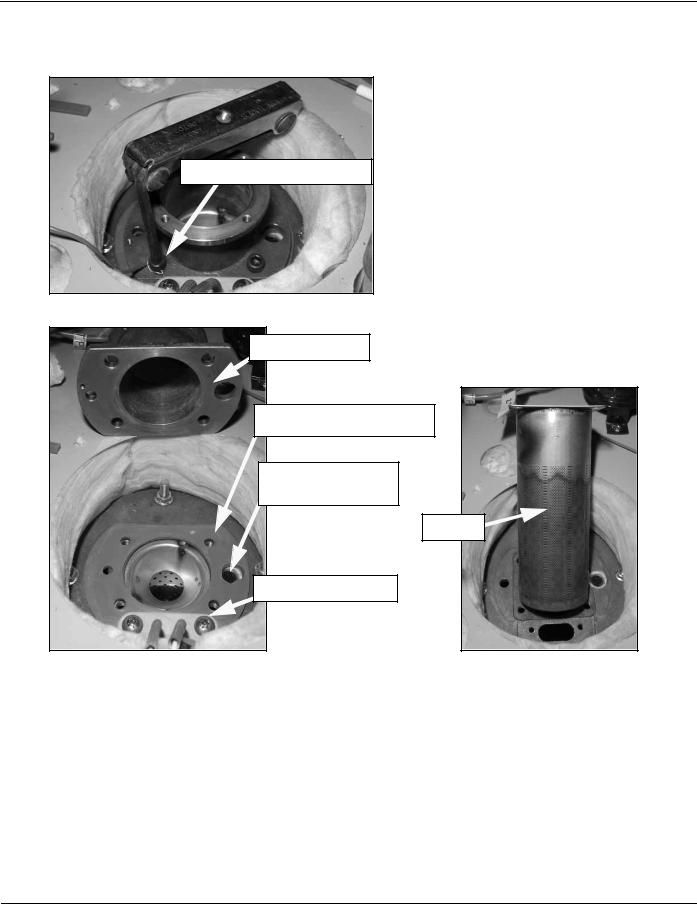
Burner/Blower Removal (cont)
1/4” Hex Machine Screws
Blower Adapter
BLOWER/BURNER REMOVAL PROCEDURE (CONT)
9Remove 4 blower adapter 1/4” hex machine screws. Do not over tighten when reinstalling - torque should not exceed 40 inch lbs.
10Remove the blower adapter.
11Be extremely careful when handling the Sight Glass inside the Burner View Port (page 11) this can easily be dropped and lost - and the water heater must have the sight glass in place to operate safely.
12Remove the hot surface igniter - 2 Phillips head screws.
13Remove the blower adapter gasket. Gasket may be reused if not damaged or showing signs of excessive wear.
14Lift the burner up and out.
Blower Adapter Gasket
Sight Glass inside
 Burner View Port
Burner |
Hot Surface Igniter
Service Notes - Blower Flange & Blower Adapter Gaskets.
Whenever the blower or burner is removed for service DO NOT overtighten the machine screws that hold the blower flange to the blower adapter (page 12) or the blower adapter to the water heater tank (above). Torque on these screws should not exceed 40 inch lbs.
If these mounting screws are overtightened the gaskets will be squeezed and deformed from their natural shape. This can partially block the flow of the fuel air mixture and cause rough starting, rough operation and ignition failure.
If these gaskets are deformed from overtightening the mounting screws it can also lead to gasket leakage. Hot flue gases leaking from these points can burn up wiring, igniters, and other components.
Technical Literature Department |
13 of 52 |
Ashland City, TN © 2008 |
Servicing should only be performed by a Qualified Service Agent |
|
|
ULTRA HIGH EFFICIENCY POWER VENT/POWER DIRECT VENT - SERVICE MANUAL
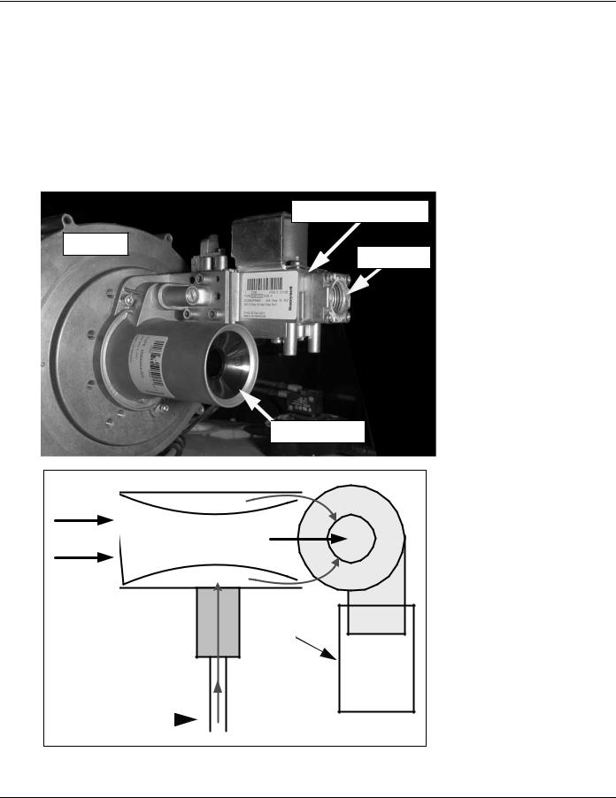
VENTURI
A Venturi is connected to the inlet of the blower. All combustion air flows through the Venturi.
The outlet of the 24 VAC gas valve connects directly to the side of the Venturi. Fuel gas flows from the outlet of the gas valve into the side of the Venturi directly.
Inside the Venturi there is a cone shaped restrictor that constricts the air passage to the blower inlet. As air enters the constriction point it’s velocity increases. A pressure drop occurs at this point and creates a negative pressure in the cavity between the cone shaped restrictor and the Venturi housing. This negative pressure “pulls” gas from the outlet of the gas valve into the blower where it is mixed with combustion air and then supplied to the burner. See the images below.
24 VAC Gas Valve
Blower
Gas Inlet

 Venturi Inlet
Venturi
Negative Pressure |
Blower |
Velocity Increases
Combustion Air At Constriction Point
Pressure Drops
Negative Pressure |
|
GAS VALVE |
Burner |
|
Supply Gas 
Technical Literature Department |
14 of 52 |
Ashland City, TN © 2008 |
Servicing should only be performed by a Qualified Service Agent |
|
|

ULTRA HIGH EFFICIENCY POWER VENT/POWER DIRECT VENT - SERVICE MANUAL
GAS VALVE
The outlet of the gas valve is connected by flange directly to the side of the Venturi (page
14). There is no manifold gas line on the water heater. A gas orifice with gasket is fitted into the gas valve’s outlet flange. See the images below.
Gas Valve Removal
The gas valve must be removed to inspect the gas orifice. There are 3 - 5/32” hex head screws that secure the gas valve to the Venturi. Long T handle hex wrenches (8-10”) will save considerable time when removing/installing the gas valve, blower and burner.
|
|
24 VAC Gas Valve |
5/32” hex wrench |
|
Venturi |
GAS VALVE REMOVAL PROCEDURE
1Ensure power to the water heater is turned off.
2Turn off the supply gas shut off valve.
3Disconnect supply gas line to water heater.
4Remove 3 gas valve mounting screws - 5/32” hex head machine screws. Support gas valve body when removing last screw. Long T handle hex wrenches (8-10”) will save considerable time when removing/installing the gas valve.
5Carefully lift gas valve body off of flange connection on Venturi.
6Gas orifice and gasket are now accessible.
Gas Orifice 24 VAC Gas Valve
& Gasket
Venturi |
Gas Orifice
& Gasket
Natural Gas Orifice |
0.191” |
Propane Gas Orifice |
0.162” |
|
|
|
|
Gasket |
Orifice |
|
|
Technical Literature Department |
15 of 52 |
Ashland City, TN © 2008 |
Servicing should only be performed by a Qualified Service Agent |
|
|
ULTRA HIGH EFFICIENCY POWER VENT/POWER DIRECT VENT - SERVICE MANUAL
GAS PRESSURE TESTING
The water heater covered in this Service Manual is rated at 100,000 Btu/hr input. It is certified for elevations up to 10,100 feet (3079 meters) without adjustment. Call the technical support phone number shown on the water heater labeling before operating the water heater at higher elevations.
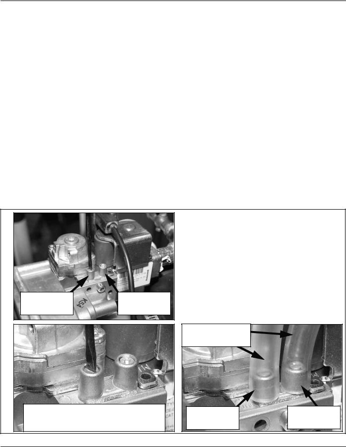
Service Notes - Checking Gas Pressures
Manifold and supply gas pressure can be measured at two test ports on the water heater’s gas valve. The manifold test port is closest to the blower housing and the supply test port is furthest. The valve in each test port is opened/closed with a small slotted screwdriver.
Manifold gas pressure will run at 0.00” W.C. or lower, in a negative pressure, depending on
the operating state or mode the control system is currently in (see Venturi on page 14).
Manifold gas pressure will be considerably lower, -6.50” to -7.50” W.C. during the pre/post purge modes when the blower is running and the gas valve is closed. When the gas valve
opens (energized) gas entering the Venturi will cause a rise in manifold gas pressure.
Manifold gas pressure will vary depending on vent/intake air pipe lengths. Manifold gas pressure will typically be 0.00” W.C. to +0.05” W.C. during the heating mode.
There may also be a drop in supply gas pressure noticed when the water heater’s gas valve opens. Seeing a rise in manifold pressure and a corresponding drop in supply gas pressure confirms the gas valve is opening and gas is flowing to the burner. The procedure for checking manifold and supply gas pressures is shown in the illustrations that follow.
Manifold Gas |
Supply Gas |
Test Port |
Test Port |
Turn test port needle valves counter-clockwise to open and clockwise to close. Always close test ports when finished and check for leaks
CHECKING GAS PRESSURES
1Ensure power to the water heater is turned off.
2Turn off the supply gas shut off valve.
3Open the manifold and supply gas pressure test ports on the gas valve. Turn the needle valve slotted heads 1/2 to 1 full turn counterclockwise with a small slotted screwdriver.
4Attach sensing tube from 2 digital manometers (see tool requirements page 3) to each gas pressure test port on the gas valve as shown.
CONTINUED ON NEXT PAGE
Sensing Tubes |
|
From Manometers |
|
Manifold Gas |
Supply Gas |
Test Port |
Test Port |
Technical Literature Department |
16 of 52 |
Ashland City, TN © 2008 |
Servicing should only be performed by a Qualified Service Agent
Loading...