


On-Demand Water Heater
Installation Manual and Owner’s Guide
R D |
|
|
ANSI Z21.10.3 CSA 4.3 |
510C |
|
model only |
||
|
Gas Tankless Water HeaterTM
Suitable for combination potable water heating and space-heating.
Please refer to local codes for space-heating compliance.
FEATURING
•ENDLESS HOT WATER
•ON-DEMAND USAGE
•COMPACT, SPACE SAVING
•ENERGY CONSERVATION
•COMPUTERIZED SAFETY
•ELECTRONIC IGNITION
•Complies with SCAQMD Rule 1146.2 for Low NOx Emissions of 14 ng/J or 20 ppm
•CONCENTRIC VENT
•EASY GAS CONVERSION
•EASY-LINK SYSTEM*
•MULTI-UNIT SYSTEM* *(510C model only)
Models
•110C
•310C
•510C
If the information in these instructions is not followed exactly, a fire or explosion may
WARNING resultcausingpropertydamage, personal injury or death.
-Do not store or use gasoline or other flammable vapors and liquids in the vicinity of this or any other appliance.
-WHAT TO DO IF YOU SMELL GAS
•Do not try to light any appliance.
•Do not touch any electric switch, do not use any phone in your building.
•Immediately call your gas supplier from a neighbor's phone. Follow the gas supplier's instructions.
•If you cannot reach your gas supplier, call the fire department.
-Installation and service must be performed by a qualified installer, service agency or the gas supplier.
If you have any questions, please call or write to:
500 Tennessee Waltz Parkway
Ashland City, TN 37015
Toll Free: 1-877-737-2840

Contents
CONTENTS |
|
Installation Manual |
|
SPECIFICATIONS........................................................................................................................... |
4 |
INTRODUCTION........................................................................................................................... |
5 |
SAFETY GUIDELINES.................................................................................................................... |
6 |
INSTALLATION.............................................................................................................................. |
7 |
General..................................................................................................................................... |
7 |
Clearances................................................................................................................................ |
9 |
Included accessories................................................................................................................ |
9 |
Optional items.......................................................................................................................... |
9 |
Warning for installations........................................................................................................ |
11 |
High-altitudeinstallations...................................................................................................... |
12 |
Ventinginstructions............................................................................................................... |
13 |
Gas supply and gas pipe sizing............................................................................................... |
18 |
Water connections................................................................................................................ |
20 |
Electrical connections............................................................................................................ |
21 |
Temperature remote controller............................................................................................ |
22 |
Easy-Link System.................................................................................................................... |
24 |
Multi-Unit System.................................................................................................................. |
26 |
APPLICATIONS............................................................................................................................ |
27 |
INITIAL OPERATION................................................................................................................... |
29 |
Owner's Guide |
|
OPERATING SAFETY................................................................................................................... |
31 |
NORMAL OPERATION................................................................................................................ |
33 |
General.................................................................................................................................. |
33 |
Temperature settings............................................................................................................. |
34 |
Flow....................................................................................................................................... |
37 |
Freeze protection system....................................................................................................... |
37 |
Maintenance and service....................................................................................................... |
38 |
Unit draining and filter cleaning............................................................................................ |
38 |
TROUBLESHOOTING................................................................................................................... |
39 |
General................................................................................................................................... |
39 |
Error codes............................................................................................................................ |
41 |
COMPONENTS DIAGRAM.......................................................................................................... |
44 |
PARTS LIST.................................................................................................................................. |
48 |
OUTPUT TEMPERATURE CHART.................................................................................................... |
50 |
LIMITED WARRANTY.................................................................................................................. |
51 |
2 Page

Installation Manual
Installation Manual
CONGRATULATIONS
Congratulations and thank you for choosing our tankless water heater. Before use, we recommend that you read through this safety manual carefully. Please refer to the back of the manual for details about the warranty. Keep this manual for future reference.
If you lose the manual, contact the manufacturer or your local distributor or download from the manufacturer's website. When you call, please tell us the product name and the serial number of your unit written on the rating plate of the water heater.
3 Page

Installation Manual
Specifications
SPECIFICATIONS
Model |
|
110C |
|
|
Natural Gas Input |
BTU/h |
Min.: 15,000 |
Min.: 15,000 |
|
(Operating Range) |
Max.: 140,000 |
Max.: 190,000 |
||
|
||||
Gas Connection |
|
|
3/4" NPT |
|
Water Connections |
|
|
3/4" NPT |
|
Water Pressure* |
psi |
|
15 - 150 (0.1 - 1) |
|
(Mpa) |
|
|||
Natural gas |
|
|
||
" W.C. |
|
Min. 5.0 (1.24) |
||
Inlet Pressure |
(kPa) |
|
Max. 10.5 (2.61) |
|
Weight |
lbs. (kg) |
|
51 (23) |
|
Dimensions |
inch |
|
H 20.5 x W 13.7 x D 10.5 |
|
mm |
|
H 520 x W 350 x D 266 |
||
|
|
|||
Ignition |
|
|
Electric Ignition |
|
Supply |
VAC / Hz |
|
120 / 60 |
|
Operation |
W / A |
53 / 0.58 |
|
|
Standby |
W / A |
2 / 0.06 |
|
|
Electric Consumption Freeze- |
W / A |
99 / 0.83 |
|
|
Protection |
|
|
|
*Maximum flow may need water pressure equal to or above 40 psi.
NOTE:
510C
Min.: 15,000
Max.: 199,000
72 / 0.85
3 / 0.07
100 / 0.83
•Check the rating plate to ensure this product matches your specifications.
•In accordance with ANSI Z21.10.3, CO emission does not exceed 400 PPM for normal input.
•The manufacturer reserves the right to discontinue, or change at any time, specifications or designs without notice and without incurring obligations.
4 Page
Installation Manual
Introduction
INTRODUCTION
•This manual provides information necessary for the installation, operation, and maintenance of the water heater.
•The model description is listed on the rating plate which is attached to the side panel of the water heater.
•Please read all installation instructions completely before installing this product.
•If you have any problems or questions regarding this equipment, consult the manufacturer or its local representative.
•This appliance is an on-demand, tankless water heater. It is designed to efficiently supply endless hot water for your needs.
•The 110C, 310C, and 510C models are only to be installed indoors with concentric venting.
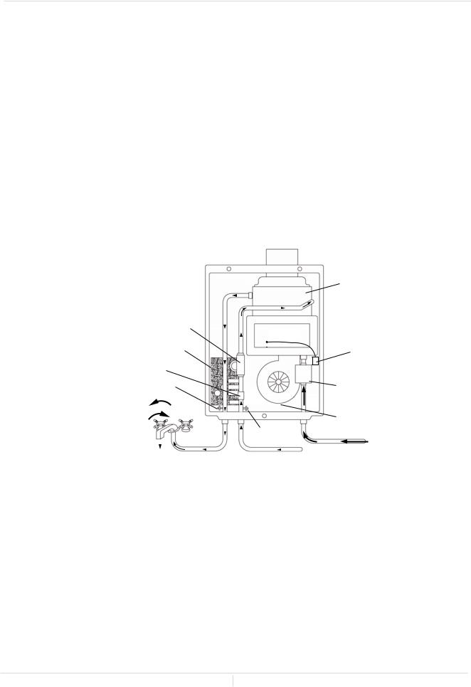
•The principle behind tankless water heaters is simple:
Exhaust vent and combustion air intake collar
|
|
|
|
|
|
|
|
|
|
|
|
|
|
|
|
|
|
|
6 |
|
|
|
|
|
|
|
|
|
|
|
|
|
|
|
|
|
|
|
Heat exchanger |
|
|
|
|
|
|
|
|
|
|
|
|
|
|
|
|
|
|
||
Flow adjustment valve |
|
|
|
|
|
|
|
|
|
|
|
5 |
|
|
|||||
|
|
|
|
|
Burners |
|
4 |
||||||||||||
|
|
|
|
|
|
||||||||||||||
|
|
|
|
||||||||||||||||
4 |
Computer board |
|
|
|
|
|
|
||||||||||||
|
|
|
|
|
|||||||||||||||
|
|
|
|
|
|
|
|
|
|
|
|
|
|||||||
|
|
|
|
|
|
|
|
|
|
|
|
|
Igniter |
||||||
|
|
|
|
|
|
|
|
|
|
||||||||||
3 |
Flow sensor |
|
|
|
|
|
|
|
|
|
|
|
|
|
|
|
|
4 |
|
|
|
|
|
|
|
|
|
|
|
|
|
|
|
|
|
||||
|
7 Thermistor |
|
|
|
|
|
|
|
|
|
|
||||||||
|
|
|
|
|
|
|
|
|
|
|
Gas valves |
||||||||
|
8 |
|
1 |
|
|
|
|
|
|
|
|
|
|
|
|
|
|
|
4 |
|
|
|
|
|
|
|
|
|
|
|
|
|
|
|
|
|
|||
|
|
|
|
|
|
|
|
|
|
|
|
|
|
|
|
||||
|
|
|
|
|
|
|
|
|
|
|
|
|
|
|
|
|
|||
|
|
|
|
|
|
|
|
|
|
|
|
|
|
|
|
|
|
Fan motor |
|
Hot water fixture |
|
|
|
|
|
|
|
7 Thermistor |
|
|
|
||||||||
|
|
|
|
|
|
|
|
|
|
||||||||||
|
|
|
|
|
|
|
|
|
|
||||||||||
|
|
|
|
|
|
|
|
|
|
||||||||||
|
|
|
|
|
|
|
|
|
|
|
|
|
|
|
|
|
|
|
|
7 Hot water outlet |
|
|
|
|
|
|
|
|
|
|
|
|
|
|
|
2 |
Gas inlet |
||
|
|
|
|
|
|
|
Cold water inlet |
||||||||||||
|
|
|
|
|
|
|
|
|
|
|
|||||||||
|
|
|
|
|
|
|
|
|
|
|
|
||||||||
*This diagram illustrates tankless water heater design concepts only and does not accurately represent the water heater’s physical description.
1.A hot water fixture is turned on.
2.Water flows through the heater.
3.The water flow sensor detects the water flow.
4.The computer initiates the fan motor and gas valve to let gas flow through the heater and sends a signal to the igniter to create an ignition spark.
5.The gas ignites and flames appear within the burner chamber.
6.Water is heated as it flows through the heat exchanger.
7.Using thermistors to measure temperatures throughout the water heater, the computer modulates the gas and water valves to ensure proper output water temperature and hot water outflows.
8.When the fixture is turned off, the unit shuts down.
5 Page

Installation Manual
Safety Guidelines
SAFETY GUIDELINES
SAFETY DEFINITION
|
|
|
|
Indicates an imminently hazardous situation which, if not avoided, will result |
|
DANGER |
|
|
in death or serious injury. |
|
|
|
|
|
|
|
|
|
Indicates an imminently hazardous situation which, if not avoided, could |
|
|
|
|
|
|
WARNING |
|
|
result in death or serious injury. |
|
|
|||
|
|
|
|
Indicates an imminently hazardous situation which, if not avoided, could |
|
|
|
|
|
|
CAUTION |
|
|
result in minor or moderate injury. |
|
|
|
GENERAL
1. Follow all local codes, or in the absence of local codes, follow the current edition of the National Fuel Gas Code:
ANSI Z223.1/NFPA 54 in the USA or CAN/CSA B149.1, Natural Gas and propane installation code in Canada.
2. Properly ground the unit in accordance with all local codes or in the absence of local codes, with the current edition of the National Electrical Code: ANSI/NFPA 70 in the USA or CSA standard C22.1 Canadian Electrical Code Part 1 in Canada.
3. Carefully plan where you intend to install the water heater. Please ensure:
• Your water heater will have enough combustion air and proper ventilation.
• Locate your heater where water leakage will not damage surrounding areas. (Please refer to p. 8.)
4. Check the rating plate for the correct GAS TYPE, GAS PRESSURE, WATER PRESSURE and ELECTRIC RATING. If this unit does not match your requirements, do not install and consult with the manufacturer. The water heater is configured only for use with Natural Gas at the factory. If the appliance is used with propane gas, conversion to propane gas with an included conversion kit (LP Conversion Kit: 319143-580) is required. The conversion must be done by a qualified service agent or a gas utility serviceman in accordance with this instruction and all codes and requirements of the authority having jurisdiction. Failure to follow instructions could result in serious injury or property damage. The agent performing this work assumes responsibility for this conversion. (Refer to the gas conversion leaflet.)
5. If any problem should occur, turn off all hot water fixtures and turn off the gas. Then call a trained technician or the Gas Company or the manufacturer.
• Water temperatures over 125 °F (52 °C) can cause severe burns instantly or death from scalding. The water temperature is set at 120 °F (50 °C) from the factory to minimize any scalding risk. Before bathing or showering always check the water temperature.
• Do not store or use gasoline or other flammables, vapors, or liquids in the vicinity of this appliance.
WARNING • Do not reverse the water and/or gas connections as this will damage the gas valves and can cause severe injury or death. Follow the diagram on p. 20 when installing your water heater.
•The conversion to propane must be done by a qualified service agent or a gas utility serviceman in accordance with this instruction and all codes and requirements of the authority having jurisdiction. Failure to follow instructions could result in serious injury or property damage. The qualified agent performing this work assumes responsibility for this conversion.
•Do not use this appliance if any part has been in contact with or been immersed in water. Immediately call a licensed plumber, a licensed gas fitter, or a professional service technician to inspect and/or service the unit if necessary.
•Do not disconnect the electrical supply if the ambient temperature will drop below freezing. The Freeze Protection System only works if the unit has electrical power. The warranty will not be covered if the heat exchanger is damaged due to freezing. Refer to the section on the Freeze Protection System on p. 37 for more information.
6 Page

Installation Manual
Installation
INSTALLATION
GENERAL
1.Follow all local codes, or in the absence of local codes, follow the current edition of the National Fuel
Gas Code: ANSI Z223.1/NFPA 54 in the USA or CAN/CSA B149.1, Natural Gas and propane installation code in Canada.
2.All gas water heaters require careful and correct installation to ensure safe and efficient operation. This manual must be followed exactly. Read the “Safety Guidelines” section.
3.The manifold gas pressure is preset at the factory. It is computer controlled and should not need adjustment.
4.Maintain proper space for servicing. Install the unit so that it can be connected or removed easily. Refer to the "Clearances" section on p. 9 for proper clearances.
5.The electrical connection requires a means of disconnection, to terminate power to the water heater for servicing and safety purposes.
6.Do not install the unit where the exhaust vent is pointing into any opening in a building or where the noise may disturb your neighbors. Make sure the vent termination meets the required distance by local code from any doorway or opening to prevent exhaust from entering a building. (Refer to p. 11, 16, and 17.)
7.Carefully plan the installation location of the heater and vent terminations. Particles from flour, aerosols, lint, and other contaminants may clog the air intake. This could reduce the operation of the fan causing improper combustion and reduced life of the water heater. Ensure that the area around the heater and vent termination is free of dust and debris. Regular maintenance is recommended is environments with these items in the air.
8.For the 110C, 310C, and 510C models: A condensate collector and trap (100266140 & 100266139) are required to be installed in the venting system when there is more than 8 feet (2.4 m) of equivalent vent length, not including the sidewall termination. 87° elbow is equivalent to 5 ft. (1.5 m) of vent
length. The condensate collector must be installed on the heater's flue. The condensate trap and collector are required on all vertical installations.
7 Page
Installation Manual
Installation
WARNING
CAUTION
•Installation and service must be performed by a qualified installer (for example, a licensed plumber or gas fitter). Otherwise, the warranty will be void.
•The installer (licensed professional) is responsible for the correct installation of the water heater and for compliance with all national, state / provincial, and local codes.
•The manufacturer does not recommend installing the water heater in a pit or location where gas and water can accumulate.
•Do not have the vent terminal pointing toward any operating window, door, or opening into a building.
•Do not install next to any source of airborne debris, such as a clothes dryer, that can cause debris to be trapped inside the unit cabinet.
•The manufacturer does not suggest installing the water heater in an attic due to safety issues. If you install the water heater in an attic:
•Make sure the unit will have proper ventilation.
•Keep the area around the water heater and its termination clean. When dust collects on the flame sensor, the water heater will shut down and produce an error code.
•Place the unit for easy access for service and maintenance.
•A drain pan, or other means of protection against water damage, is recommended to be installed under the water heater in case of leaks. The manufacturer is not responsible for damage due to water leak.
•The warranty will not cover damage caused by water quality.
•Only potable water or potable water / glycol mixtures can be used with this water heater. Do not introduce pool or spa water, or any chemically treated water into the water heater.
•Water hardness levels must not exceed 7 grains per gallon (120 ppm) for single family domestic applications or more than 4 grains per gallon (70 ppm) for all other types of applications. Water hardness leads to scale formation and may affect / damage the water heater. Hard water scaling must be avoided or controlled by proper water treatment.
•Water pH levels must be between 6.5 and 8.5.
•Well water must be treated.
•Do not install the unit where water, debris, or flammable vapors may get into the flue terminal.
•Although the water heater is designed to operate with minimal sound, the manufacturer does not recommend installing the unit on a wall adjacent to a bedroom, or a room that is intended for quiet study or meditation, etc.
•Locate your heater close to a drain where water leakage will not do damage to surrounding areas. As with any water heating appliance, the potential for leakage at some time in the life of the product does exist. The manufacturer will not be responsible for any water damage that may occur. If you install a drain pan under the unit, ensure that it will not restrict the combustion air flow.
8 Page

|
|
|
|
|
|
Installation Manual |
|
|
|
|
|
|
|
|
Installation |
|
|
CLEARANCES |
|
|
Top |
||
|
|
Maintain all |
clearances around |
|
Side |
Back |
|
|
|
|
|
||||
|
|
the water heater. |
|
|
|
||
|
|
|
Front |
|
|||
|
|
|
|
|
Side |
||
|
|
|
|
|
|
|
|
Model |
Top |
Bottom |
Front |
Back |
Sides |
|
|
110C |
12 in. |
12 in. |
4 in.* |
1 in. |
3 in. |
|
|
310C |
|
|
|||||
(305 mm) (305 mm) (102 mm) |
(25 mm) |
(76 mm) |
|
|
|||
510C |
|
Bottom |
|||||
|
|
|
|
|
|
||
*24 inches (610 mm) recommended for maintenance.
INCLUDED ACCESSORIES
Check that these items below are included with the water heater.
Installation manual |
Communication cable |
LP Conversion Kit (319143-580) |
|
and Owner’s guide |
510C model only |
||
|
|||
|
(320273-585) |
(319143-581) |
|
|
|
||
Qty: 1 |
Qty: 1 |
Manifold attachment : 2 Small / 1 Large |
|
Manifold gasket (319143-581): 1 |
|||
|
|
Gas conversion sticker : 1 |
|
|
|
Gas conversion instruction : 1 |
OPTIONAL ITEMS
# |
Model |
110C |
310C |
510C |
1. |
Condensate collector (100266140) |
|
|
|
and trap (100266139) |
||||
2. |
Concentric Sidewall Termination Kit |
|
|
|
3. |
Concentric Roof Termination |
|
|
|
4 |
Elbow |
|
|
|
5. |
Straight Pipe |
|
|
|
6. |
Roof Flashing |
|
|
|
7. |
Pipe Hanger |
|
|
|
8. |
Remote controller (9009069005) |
|
|
|
9 Page

|
|
Installation Manual |
|
|
Installation |
1. Condensate Collector and Trap |
2. Concentric Sidewall Termination Kit |
|
|
|
11 1/2" (292mm) |
|
|
(100266115) |
|
|
21" (533 mm) |
|
|
(100266117) |
Collector |
Trap |
It includes: One Sidewall Termination, One 87° Elbow, |
(100266140) |
(100266139) |
Two Wall Plates. |
3. Concentric Roof Termination |
4. Elbow |
|
|
38" (965 mm) Roof Termination |
|
|
(100266118) |
|
|
45° Elbow |
87° Elbow |
|
(100266119) |
(100266132) |
5. Straight Pipe |
6. Roof Flashing |
|
10" (254 mm) Straight Pipe :(100266133) 19.5" (495 mm) Straight Pipe :(100266134) 39" (991 mm) Straight Pipe :(100266135)
7. Pipe Hanger (100266141)
Flatroof Flashing
(100266187)
Tile / Shingle Roof Flashing 1/12 to 6/12 Pitch (100266136) 8/12 to 16/12 Pitch (100266137) 6/12 to 12/12 Pitch (100266138)
8.Remote controller
9009069005 (TM-RE42)
This remote can be added to the heater, in addition to the built-in controller.
10 Page
Installation Manual
Installation
WARNING FOR INSTALLATIONS
FOR YOUR SAFETY, READ BEFORE INSTALLATION:
• Do not install the water heater and its termination where water, debris or flammable vapors may get into the water heater and flue terminal. This may cause damage to the heater and void the
|
warranty. |
|
|
• Do not have the vent terminal pointing toward any opening into a |
|
Prohibited |
building. |
|
• Do not locate your heater in a pit or location where gas and water |
||
|
||
|
can accumulate. |
1ft.(30cm)min.USA
3ft.(91cm)min.Canada
1ft.(30cm)min.USA
3ft.(91cm)min.Canada 1ft.(30cm)min.USA 3ft.(91cm)min.Canada
12-inches (30.48 cm) above grade or anticipated snow level
Do not install the water heater vent terminator within 1 ft. (30 cm) in the USA of any air intake or building opening, and within 3 ft. (91 cm) in Canada of any air intake or building opening.
Anticipated snow level
Water heater vent terminator must be at least 2 ft. (61 cm) away from an inside corner.
2 ft.
(61 cm) min.
Inside corner
Do not install the water heater or vent termination next to a dryer or dryer vent. The water heater environment must be free from any source of airborne debris that can be trapped inside the water heater.
11 Page

Installation Manual
Installation
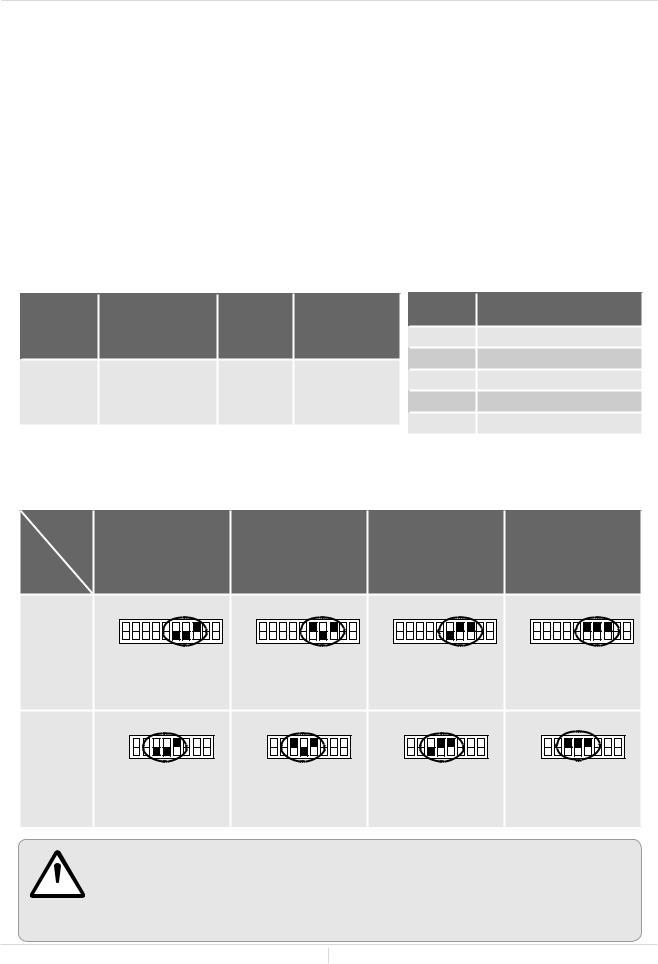
HIGH-ALTITUDE INSTALLATIONS
Check the altitude where your water heater is installed. Set DIP switches shown in the table below. The DIP switch settings are depending on the altitude.
•The black squares indicate the positions of the DIP switches for high altitude installation.
The 110C and 310C : Only adjust DIP switch No. 3, No. 4, and No.5.
The 510C : Only adjust DIP switch No. 2, No. 3, and No. 4 on the lower bank.
WARNING
•DO NOT adjust the other DIP switches for high altitude installation.
110C and 310C models |
510C model |
|
Computer board |
||
Computer board |
||
|
Bank of DIP switches |
Lower bank of DIP switches |
Installation altitude
The maximum certified or allowable installed altitude is 10,100 ft. (3,078 m) for CV models
Altitude |
0 to 2,000 ft. |
2,001 ft. to |
3,001 ft. to |
5,001 ft. to |
7,501 ft. to |
|
3,000 ft. |
5,000 ft. |
7,500 ft. |
10,100 ft. |
|||
|
(0 to 609 m) |
|||||
|
(610 m to |
(915 m to |
(1,525 m to |
(2,287 m to |
||
Model |
DEFAULT |
|||||
914 m) |
1,524 m) |
2,286 m) |
3,078 m) |
|||
|
||||||
|
ON 1 2 3 4 5 6 7 8 9 10 |
ON 1 2 3 4 5 6 7 8 9 10 |
ON 1 2 3 4 5 6 7 8 9 10 |
ON 1 2 3 4 5 6 7 8 9 10 |
ON 1 2 3 4 5 6 7 8 9 10 |
|
110C and |
OFF |
OFF |
OFF |
OFF |
OFF |
|
|
|
|
|
|
||
310C models |
No. 3 : OFF |
No. 3 : OFF |
No. 3 : OFF |
No. 3 : OFF |
No. 3 : ON |
|
|
No. 4 : OFF |
No. 4 : ON |
No. 4 : OFF |
No. 4 : ON |
No. 4 : ON |
|
|
No. 5 : OFF |
No. 5 : OFF |
No. 5 : ON |
No. 5 : ON |
No. 5 : ON |
|
|
ON 1 2 3 4 5 6 |
ON 1 2 3 4 5 6 |
ON 1 2 3 4 5 6 |
ON 1 2 3 4 5 6 |
ON 1 2 3 4 5 6 |
|
510C model |
OFF |
OFF |
OFF |
OFF |
OFF |
|
(Lower bank of |
||||||
No. 2 : OFF |
No. 2 : OFF |
No. 2 : OFF |
No. 2 : OFF |
No. 2 : ON |
||
DIP switches) |
||||||
No. 3 : OFF |
No. 3 : ON |
No. 3 : OFF |
No. 3 : ON |
No. 3 : ON |
||
|
||||||
|
No. 4 : OFF |
No. 4 : OFF |
No. 4 : ON |
No. 4 : ON |
No. 4 : ON |
|
|
|
12 Page |
|
|
||
Installation Manual
Installation
VENTING INSTRUCTIONS
-General-
DANGER
CAUTION
•Improper venting of this appliance can result in excessive levels of carbon monoxide which can result in severe personal injury or death.
•Improper installation can cause nausea or asphyxiation, severe injury or death from carbon monoxide and flue gases poisoning. Improper installation will void product warranty.
When installing the vent system, all applicable national and local codes must be followed. If you install thimbles, fire stops or other protective devices and they penetrate any combustible or noncombustible construction, be sure to follow all applicable national and local codes.
The water heater must be vented in accordance with the section “Venting of Equipment" of the current editionoftheNationalFuelGasCode:ANSIZ223.1/NFPA54intheUnitedStatesand/orSection7ofthe
CAN/CSA B149.1 Natural Gas, propane installation code in Canada, as well as applicable local building codes. The water heater is designed for a concentric venting system, which uses one pipe system with two ducts for combustion air and exhaust air. The manufacturer approves the use of Centrotherm Eco
Systems Direct Vent APNC35 venting systems on new installations. This system is furnished through the heater manufacturer. See the table below for certified vent terminations.
General rules for venting water heaters:
•Place the water heater as close as possible to the vent termination.
•Do not weld the vent pipe to the water heater’s vent collar.
•Do not cut the vent collar of the unit.
•The vent must be easily removable from the top of the water heater for normal service and inspection of the unit and vent system.
•The water heater vent must not be connected to any other gas appliance or vent stack.
•Avoid using an oversized vent pipe or using extremely long runs of the pipe.
•Do not common vent or connect any vent from other appliances to the water heater vent.
•The vent should slope towards the heater and condensate collector (100266139). The condensate trap (100266140) must be installed below the condensate collector's drain nipple to keep condensate from draining back into the heater's exhaust and causing damage. Condensate is corrosive and should be treated and disposed of according to local codes.
General rules for vent terminations:
•Avoid locating the water heater vent termination near any air intake devices. These fans can pick up the exhaust flue products from the water heater and return them to the building. This can create a health hazard.
•Locate the vent termination so that it cannot be blocked by any debris, at any time. Most codes require that the termination must be at least 12 in. (305 mm) above grade and anticipated snow line, but the installer may determine if it should be higher depending on the job site condition and applicable codes.
•A proper sidewall termination is recommended when the water heater is vented through a sidewall.
•Regarding the clearances from the exhaust termination to the air inlet or opening, refer to p 11, 16, and 17.
Use |
Vent Brand |
Description |
Model Number |
|
|
Centrotherm |
11-1/2" Concentric, Sidewall Termination Kit |
100266115 |
|
New Installation |
Eco Systems |
21" Concentric, Sidewall Termination Kit |
100266117 |
|
(New Venting) |
Direct Vent |
|||
38" Roof Termination |
100266118 |
|||
|
APNC35 |
13 Page
Installation Manual
Installation
-Vent length and No. of Elbows-
This is a Category III appliance and must be vented accordingly. For best results, a vent system should be as short and straight as possible.
•This water heater is a Category III appliance and must be vented accordingly with concentric vent approved for use with Category III or Special BH type gas vent.
•Follow the vent pipe manufacturer's instructions and the instructions in this manual when installing the vent pipe.
•Do not common vent this appliance with any other vented appliance. (Do not terminate vent inside a chimney. If the vent must go through the chimney, it must run through the top of the chimney and terminate with the roof termination listed on page 10. Install per the vent manufacturer's instructions.)
•When the horizontal vent run exceeds 5 ft. (1.5 m), support the vent run at 3 ft. (0.9 m) intervals with overhead hangers.
•The maximum length of exhaust vent piping must not exceed 43 ft. (13.1 m) (deducting 5 ft. (1.5 m) for each 87° elbow used in the venting system). Do not use more than 4 pieces of 87° elbows.
|
|
Max. No. of |
Max. Vertical and |
Vent type |
Diameter |
87° Elbows |
Horizontal (Total) |
|
|
|
Vent Length |
Concentric |
3 in. / 5 in. |
4 |
43 ft. (13.1 m ) |
(80 mm / 125 mm) |
For each 87° elbow added, deduct 5 ft. (1.5m) from max. vent length. Two 45° elbows are equivalent to one 87° elbow.
No. of 87° |
Max. Vertical |
Elbows |
or Horizontal Vent Length |
043 ft. (13.1 m)
138 ft. (11.6 m)
233 ft. (10.1. m)
328 ft. (8.5 m)
423 ft. (7.0 m)
Excludes the Concentric termination
-DIP switch settings for Vent length-
Vent |
|
|
|
|
|
length |
0 to 10 ft. |
11 to 20 ft. |
21 to 30 ft. |
31 to 43 ft. |
|
|
(0 to 3 m) |
||||
Model |
DEFAULT |
(3.1 to 6.1 m) |
(6.2 to 9.1 m) |
(9.2 to 13.1 m) |
|
|
|
|
|||
110C |
ON 1 2 3 4 5 6 7 8 9 10 |
ON 1 2 3 4 5 6 7 8 9 10 |
ON 1 2 3 4 5 6 7 8 9 10 |
ON 1 2 3 4 5 6 7 8 9 10 |
|
and |
OFF |
OFF |
OFF |
OFF |
|
310C |
No. 6 : OFF |
No. 6 : ON |
No. 6 : OFF |
No. 6 : ON |
|
models |
|||||
No. 7 : OFF |
No. 7 : OFF |
No. 7 : ON |
No. 7 : ON |
||
|
|||||
|
No. 8 : ON |
No. 8 : ON |
No. 8 : ON |
No. 8 : ON |
|
510C |
ON 1 2 3 4 5 6 7 8 |
ON 1 2 3 4 5 6 7 8 |
ON 1 2 3 4 5 6 7 8 |
ON 1 2 3 4 5 6 7 8 |
|
model |
OFF |
OFF |
OFF |
OFF |
|
(Upper bank |
No. 3 : OFF |
No. 3 : ON |
No. 3 : OFF |
No. 3 : ON |
|
of DIP |
|||||
No. 4 : OFF |
No. 4 : OFF |
No. 4 : ON |
No. 4 : ON |
||
switches) |
|||||
No. 5 : ON |
No. 5 : ON |
No. 5 : ON |
No. 5 : ON |
||
|
• The black squares indicate the positions of the DIP switches for vent length. For the 110C and 310C : Only adjust DIP switch No. 6 , No. 7, and No. 8.
 For the 510C : Only adjust DIP switch No. 3, No. 4, and No. 5 on the upper bank. WARNING • DO NOT adjust the other DIP switches for vent length.
14 Page

Installation Manual
Installation
Venting Illustrations-
For the 110C, 310C and 510C models
For details of the venting installation, refer to the Centrotherm Eco Systems Direct Vent APNC35 concentric venting installation manuals.
Horizontal Installation
Standard Sidewall kit
11.5" (292 mm):100266115 21" (533 mm):100266117
Vertical Installation
Roof termination
100266118
Tile / Shingle Foof Flashing
1/12 to 6/12 pitch: 100266136 8/12 to 16/12 pitch: 100266137 6/12 to 12/12 pitch: 100266138
Straight Pipe
10" (254 mm) : 100266133 19.5" (495 mm) : 100266134 39" (990 mm) : 100266135
Pipe Hanger
100266141
Condensate Trap &
Collector
100266139&100266140
Straight Pipe
10" (254 mm) : 100266133 19.5" (495 mm) : 100266134 39" (990 mm) : 100266135
Condensate Trap &
Collector
100266139&100266140
Pipe Hanger
100266141
Elbow
87° :100266132
15 Page

Installation Manual
Installation
-Vent termination clearances-
D
 E V
E V 
B
V
L 
INSIDE CORNER DETAIL |
|
|
|
V |
Vent terminal |
|
X |
Air supply inlet |
V |
G |
Area where is not permitted |
|
|
|
H
A
|
|
B |
|
|
|
|
B |
V |
|
|
|
|
||||
|
C |
|
|
|
|
FIXED |
M |
|
|
X |
||||||
|
|
|
|
|
|
|||||||||||
|
|
|
|
|
|
|
|
|
|
|
|
|
||||
|
|
|
|
|
V |
|
OPERABLE CLOSED |
|
|
I |
V |
|||||
|
|
|
|
|
|
|
|
X |
|
|
|
|||||
V |
FIXED |
B |
|
|
|
|
|
V |
|
|
|
|
K |
|||
|
|
|
|
|
|
|
|
|
|
|
||||||
|
CLOSED |
|
|
|
|
|
J |
|
|
|
|
|
|
|
||
|
|
|
|
|
|
|
|
|
|
|||||||
F V |
OPERABLE |
|
|
|
|
|
|
|
|
|
|
|
|
|
|
|
|
|
|
|
|
B |
|
|
|
|
|
|
|
|
|
||
|
|
|
|
|
|
A |
|
|
|
|
|
|
|
|
||
|
|
|
|
|
|
|
|
|
|
Gas meter / regulator |
|
|
|
|||
|
|
|
|
|
|
|
|
|
|
|
|
|
|
|||
|
B |
|
|
|
|
|
|
|
|
|
|
|
|
|
|
|
|
|
Canada |
U.S.A |
|
|
|
Direct-vent |
Directvent |
|
A |
Clearance above grade, veranda, porch, deck, or bal- |
1 foot (30 cm) |
1 foot (30 cm) |
|
cony |
||||
|
|
|
||
B |
Clearance to window or door that may be opened |
3 feet (91 cm) |
1 foot (30 cm) |
|
C |
Clearance to permanently closed window |
* |
* |
|
|
Vertical clearance to ventilated soffit located above |
|
|
|
D |
the vent terminator within a horizontal distance of 2 |
* |
* |
|
|
feet (61cm) from the center line of the terminator |
|
|
|
E |
Clearance to unventilated soffit |
* |
* |
|
F |
Clearance to outside corner |
* |
* |
|
G |
Clearance to inside corner |
2 feet (61 cm) |
2 feet (61 cm) |
|
H |
Clearance to each side of center line extended above |
3 feet (91 cm) |
* |
|
meter/regulator assembly |
||||
|
|
|
||
I |
Clearance to service regulator vent outlet |
3 feet (91 cm) |
* |
|
|
Clearance to non-mechanical air supply inlet to build- |
|
|
|
J |
ing or the combustion air inlet to any other applica- |
3 feet (91 cm) |
1 foot (30 cm) |
|
|
tion |
|
|
|
K |
Clearance to mechanical air supply inlet. |
6 feet (1.83 m) |
3 feet (91 cm) |
|
L |
Clearance above paved sidewalk or paved driveway |
7 feet (2.13 m) |
* |
|
located on public property |
||||
|
|
|
||
M |
Clearance under veranda, porch deck, or balcony |
1 foot (30 cm) |
* |
*For clearances not specified in ANSI Z223.1 / NFPA 54 or CAN/CSA-B149.1, please use clearances in accordance with local installation codes and the requirements of the gas supplier.
16 Page
 Loading...