


Commercial Electric
Water Heaters
STANDARD FEATURES
ADVANCED ELECTRONIC CONTROL (All Models 150kW and Down)
A. O. Smith’s new propriety electronic water heater control, provides precise + or - 1ºF temperature control, that is ideal for industrial and food service applications where exact temperatures of
hot water are needed.
Plain Text – Animated icons display detailed operational and diagnostic information. Fault or Alert messages appear if an operational issue occurs.
Low Water Cut Off – Factory standard on board low water cut-off uses a remote type probe to prevent energizing of the elements in the event of low water condition and eliminates accidental dry firing.
Progressive Modulating – Sizes the input of available elements to match current load conditions. Rotates and lead lags element loads to provide long life and equal wear .
Economy Mode Operation – Control system automatically lowers the operating set point by a programmed value during user defined time periods. Seven-day clock may be programmed for night set back and or weekend shutdown to reduce operating cost and save money.
iCOMM™ Compatible - Units can be monitored from remote locations. Call 1.888.WATER02 for more information.
Note: Units over 150KW use analog controls.
SOLID STATE MODULATING STEP CONTROL (All Models 180kW and up) –
Solid state electronic control device that modulates input to match load through progressive sequencing of steps (up to 20 steps with maximum of one per contactor).
GLASSLINED TANK – Tank interior is coated with glass specially developed for use in water heaters. Tanks rated at 125 psi working pressure; 150 psi or 160 psi working pressure is optional. Vermin proof fiber glass insulation reduces costly heat loss. Constructed to Section IV of ASME code, and UL standards. Tanks have channel skid base. A 4” x 6” handhole is furnished on 500, 600 and 700-gallon models;
11” x 15” manhole is furnished on 800-gallon and larger sizes.
INCOLOY IMMERSION HEATERS – Heavy-duty medium watt density elements (three/immersion heater) have incoloy sheathing: provide excellent protection against oxidation and scaling. The input ranges from 15KW to 3000KW (see accompanying chart).
FUSING – Control and power circuit fusing to meet N.E.C.
COMPLIANCE – Meets the standby loss requirements of the U.S. Department of Energy and current edition of ASHRAE/IESNA 90.1.
MAGNETIC CONTACTOR(S) – Heavy duty UL rated for 100,000 cycles.
OTHER STANDARD FEATURES
Color-coded circuitry for easier servicing
Anode rods for maximum corrosion protection
Standard voltages include 208, 240, 480, 600 volt single or three-phase.
For other voltages consult factory. Factory-installed terminal block(s) Cabinet has baked enamel finish Prewired element terminal leads Temperature and pressure relief valve 2” dial temperature gauge
OPTIONAL DUAL-ENERGY SOURCE CAPABILITY – Provides emergency back up energy source or winter/summer boiler operation. Can be specified with optional water to water or steam to water heat exchangers. Both single and double-wall heat exchangers are available. Complete control packages can be factory-installed for hook-up and run capability.
LIMITED WARRANTY OUTLINE – If the tank should leak any time during the first three years, under the terms of the warranty, A. O. Smith will repair or replace the heater; installation, labor, handling repair or replace the heater; installation, labor, handling and local delivery extra. THIS OUTLINE IS NOT A WARRANTY. For complete information, consult the written warranty or A. O. Smith. Warranty does not apply to product installed outside of the United States of America or its territorial possessions and Canada.
RFebruaryvised January2010R 2013
DVE-150 THRU 10,000 DHE-200 THRU 10,000
Low Lead Content
Page 1 of 4
AOSCE15500
Commercial Electric
Water Heaters
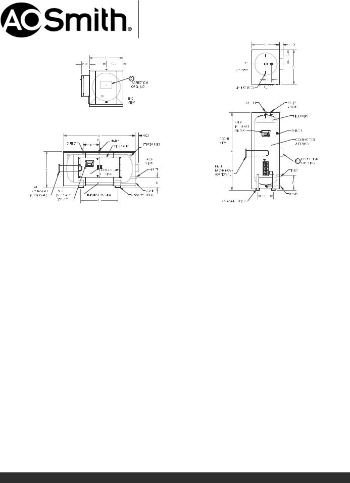
|
Nominal |
Maximum |
|
Width |
|
|
|
Skid |
Inspection |
Inlet |
|
Relief |
|
A. O. Smith |
Gallon |
kW |
Height |
(Length) |
Depth |
|
|
Spacing |
Opening |
Outlet |
Drain |
Valve |
|
Model |
Capacity |
Input |
A |
B |
C |
D |
E |
F |
G |
Opening |
Opening |
Opening** |
|
|
|
|
|
|
|
|
|
|
|
|
|
|
|
|
|
|
|
HORIZONTAL ELECTRIC STORAGE HEATER |
|
|
|
|
|||||
DHE-200 |
200 |
180 |
38-1/2 |
77 |
36 |
10-1/2 |
17-1/2 |
31 |
|
1-1/2 |
3/4 |
3/4 |
|
DHE-250 |
250 |
240 |
38-1/2 |
91 |
36 |
10-1/2 |
24 |
48 |
|
1-1/2 |
3/4 |
1 |
|
DHE-300 |
300 |
300 |
44-1/2 |
81 |
42 |
8-1/4 |
17 |
36 |
Optional |
2 |
3/4 |
1 |
|
DHE-350 |
350 |
330 |
44-1/2 |
93 |
42 |
8-1/4 |
23 |
48 |
|
2 |
3/4 |
1 |
|
DHE-400 |
400 |
390 |
44-1/2 |
100 |
42 |
8-1/4 |
26-1/2 |
55 |
|
2 |
3/4 |
1 |
|
DHE-500 |
500 |
480 |
51 |
94 |
48 |
14 |
24 |
48 |
4” x 6” |
2 |
1-1/4 |
1 |
|
DHE-600 |
600 |
600 |
51 |
109 |
48 |
14 |
32 |
64 |
2 |
1-1/4 |
1 |
||
Handhole |
|||||||||||||
DHE-700 |
700 |
690 |
51 |
121 |
48 |
14 |
38 |
76 |
2 |
1-1/4 |
1 |
||
|
|||||||||||||
DHE-800 |
800 |
780 |
57 |
111 |
54 |
16-1/2 |
32 |
64 |
|
2 |
1-1/2 |
1 |
|
DHE-1000 |
1000 |
990 |
61 |
111 |
60 |
16-1/2 |
29-1/2 |
59 |
|
3 |
1-1/2 |
1 |
|
DHE-1250 |
1250 |
1200 |
61 |
138 |
60 |
16-1/2 |
43 |
86 |
|
3 |
1-1/2 |
1 |
|
DHE-1500 |
1500 |
1500 |
61 |
150 |
60 |
16-1/2 |
50 |
98 |
11” x 15” |
3 |
1-1/2 |
1 |
|
DHE-2000 |
2000 |
1980 |
70 |
177 |
66 |
20 |
60 |
120 |
3 |
2 |
1-1/4 |
||
Manhole |
|||||||||||||
DHE-3000 |
3000 |
3000 |
76 |
211 |
72 |
20 |
72-1/2 |
131 |
3 |
2 |
1-1/2 |
||
|
|||||||||||||
DHE-5000 |
5000 |
3000 |
82 |
296 |
78 |
20-1/2 |
113-1/2 |
195 |
|
3 |
2 |
1-1/2 |
|
DHE-7500 |
7500 |
3000 |
94 |
317 |
90 |
21-1/2 |
121 |
218 |
|
4 |
2 |
1-1/2 |
|
DHE-10,000 |
10,000 |
3000 |
106 |
345 |
102 |
22 |
132 |
220 |
|
4 |
2 |
1-1/2 |
|
|
|
|
|
VERTICAL ELECTRIC STORAGE HEATER |
|
|
|
|
|||||
DVE-140 |
140 |
150 |
83-1/2 |
30 |
37 |
16 |
6 |
17 |
|
1-1/4 |
3/4 |
3/4 |
|
DVE-150 |
150 |
150 |
83-1/2 |
30 |
37 |
16 |
6 |
17 |
|
1-1/4 |
3/4 |
3/4 |
|
DVE-150L |
150 |
150 |
59-1/2 |
36 |
43 |
17-1/2 |
6 |
21 |
|
1-1/4 |
3/4 |
3/4 |
|
DVE-200 |
200 |
180 |
79-1/2 |
36 |
43 |
17-1/2 |
6 |
21 |
Optional |
1-1/2 |
3/4 |
3/4 |
|
|
|
|
|
|
|
|
|
|
|
|
|
||
DVE-250 |
250 |
240 |
93 |
36 |
43 |
17-1/2 |
6 |
21 |
1-1/2 |
3/4 |
1 |
||
|
|||||||||||||
DVE-300 |
300 |
300 |
83-1/2 |
42 |
49 |
19 |
6 |
25-1/2 |
|
2 |
3/4 |
1 |
|
DVE-350 |
350 |
330 |
95-1/2 |
42 |
49 |
19 |
6 |
25-1/2 |
|
2 |
3/4 |
1 |
|
DVE-400 |
400 |
390 |
102-1/2 |
42 |
49 |
19 |
6 |
25-1/2 |
|
2 |
3/4 |
1 |
|
DVE-500 |
500 |
480 |
97 |
48 |
55 |
21 |
6 |
30 |
4” x 6” |
2 |
1-1/4 |
1 |
|
DVE-600 |
600 |
600 |
112 |
48 |
55 |
21 |
6 |
30 |
2 |
1-1/4 |
1 |
||
Handhole |
|||||||||||||
DVE-700 |
700 |
690 |
124 |
48 |
55 |
21 |
6 |
30 |
2 |
1-1/4 |
1 |
||
|
|||||||||||||
DVE-800 |
800 |
780 |
116 |
54 |
61 |
23 |
8 |
34 |
|
2 |
1-1/2 |
1 |
|
DVE-1000 |
1000 |
990 |
116 |
60 |
67 |
24-1/2 |
10 |
38 |
|
3 |
1-1/2 |
1 |
|
DVE-1250 |
1250 |
1200 |
143 |
60 |
67 |
24-1/2 |
10 |
38 |
|
3 |
1-1/2 |
1 |
|
DVE-1500 |
1500 |
1500 |
155 |
60 |
67 |
24-1/2 |
10 |
38 |
11” x 15” |
3 |
1-1/2 |
1 |
|
DVE-2000 |
2000 |
1980 |
183 |
66 |
73 |
25 |
12 |
42-1/2 |
3 |
2 |
1 |
||
Manhole |
|||||||||||||
DVE-3000 |
3000 |
3000 |
217 |
72 |
79 |
27-1/2 |
14 |
47 |
3 |
2 |
1-1/2 |
||
|
|||||||||||||
DVE-5000 |
5000 |
3000 |
309 |
78 |
85 |
30 |
14 |
51 |
|
3 |
2 |
1-1/2 |
|
DVE-7500 |
7500 |
3000 |
330 |
90 |
97 |
30 |
14 |
59-1/2 |
|
4 |
2 |
1-1/2 |
|
DVE-10,000 |
10,000 |
3000 |
358 |
102 |
109 |
30 |
14 |
68 |
|
4 |
2 |
1-1/2 |
|
*Complete Model Number includes the desired kW at end, e.g.: DVE-500-120 when kW = 120. **Size may vary according to kW input.
Minimum installation clearances required. 30” from front, 12” from top, and 24” from right side.
For Technical Information and Automated Fax Service, call 800-527-1953. A. O. Smith reserves the right to make product changes or improvements without prior notice.
Revised January 2013 |
Page 2 of 4 |
February 2010R |
www.hotwater.com |
AOSCE15500 |
 Loading...