


Instruction Manual
COMMERCIAL ELECTRIC AIR-TO-WATER HEAT PUMP WATER HEATER
820 SW 41st Street |
Renton, WA 98057 |
MODELS AWH-35 to AWH-170 SERIES 100
INSTALLATION - OPERATION - SERVICE MAINTENANCE - LIMITED WARRANTY
FOR INDOOR INSTALLATION ONLY
Read and understand this instruction manual and the safety messages herein before installing, operating or servicing this water heater.
Failure to follow these instructions and safety messages could result in death or serious injury.
This manual must remain with the water heater.
PLACE THESE INSTRUCTIONS ADJACENT TO HEAT PUMP AND NOTIFY OWNER TO KEEP FOR FUTURE REFERENCE.
PRINTED 0114 |
318653-000 |

TABLE OF CONTENTS
TABLE OF CONTENTS 3 SAFE INSTALLATION, USE AND SERVICE 4
GENERAL SAFETY INFORMATION 5
Precautions 5 Grounding Instructions 5
INTRODUCTION 6
Qualifications 6 Preparing For The Installation 6
Principle Of Operation 7 The Refrigeration Cycle 7
Air Temperature Range 7 Water Temperature Range 7 Refrigerant Charge 7
Equipment Disposal 7 FEATURES AND COMPONENTS 8
Product Illustrations 8
Rough In Dimensions 9
Performance Specifications 9
INSTALLATION REQUIREMENTS 10 Water Temperature 10
Maximum System Temperature 10
Inlet & Outlet Water Temperature 10 Air Temperature 10 Entering Air Temperature 10 Locating The Water Heater 10
Indoor Installation Only 10
Freezing Temperatures 10 Coastal Regions 10 Heat Source 10 Conditioned Space 10
Unconditioned Space 11
Clearances 11 Electrical Requirements 11 Voltage & Amperage Ratings 11 Minimum Circuit Ampacity & Maximum Fuse Size 12
Minimum Wire Size 12
Water Piping 13
Maximum Pipe Length 13 Minimum Pipe Size 13
Pipe Support 13 Pipe Insulation 13 Cold Water Supply 13
Water Pressure 13 Closed Water Systems 13
Thermal Expansion 13 Mixing Valves 13
Condensate Removal 14 Contaminated Water 14 Temperature - Pressure Relief Valve 14 Tank Selection 14 Contaminated Air 14
Storage & Handling 15
INSTALLATION |
|
16 |
|
Required Tools and Materials |
|
16 |
|
Installation & Start Up Tools |
16 |
||
Service Tools |
|
|
16 |
Unit Placement |
|
16 |
|
Ceiling Suspension |
|
16 |
|
Pad Mounting |
|
|
16 |
Electrical Connections |
|
17 |
|
Correct Voltage And Phase |
17 |
||
Branch Circuit Disconnect Switch |
17 |
||
Transformer Configuration 208 VAC Models |
17 |
||
Water Connections |
|
17 |
|
Installation Instructions |
|
17 |
|
Single Tank Configuration |
|
18 |
|
Two Tank Pre Heat Configuration |
18 |
||
Condensate Drain Line |
|
18 |
|
Standard Tank Thermostat |
|
18 |
|
Digital Tank Thermostat Installation |
19 |
||
Temperature Sensor Installation |
19 |
||
Air Flow and Ducting |
|
19 |
|
Duct Sizing |
|
19 |
|
Duct Insulation |
|
19 |
|
Make Duct Connections |
|
19 |
|
Building Air Pressure |
|
19 |
|
When To Install Ducting |
|
20 |
|
Supply Air Ducting |
|
20 |
|
Return Air Ducting |
|
20 |
|
Blower Assembly Adjustments |
20 |
||
INSTALLATION CHECKLIST |
|
22 |
|
START UP |
|
23 |
|
Digital Tank Thermostat |
|
24 |
|
MAINTENANCE AND SERVICE |
|
25 |
|
Routine Maintenance |
|
25 |
|
TROUBLESHOOTING |
|
27 |
|
Checking Refrigerant Charge |
|
28 |
|
Subcooling Calculation |
|
28 |
|
Superheat Calculation |
|
28 |
|
CONTROL SYSTEM ............................................................................ |
|
|
29 |
Control Board............................................................................ |
|
|
29 |
Pressure Switches .................................................................... |
|
|
29 |
Phase Monitor........................................................................... |
|
|
30 |
Compressor Overload Module .................................................. |
|
30 |
|
Delay Timers ............................................................................. |
|
|
30 |
How To Reset The Control System........................................... |
|
30 |
|
WIRING DIAGRAMS............................................................................ |
|
|
31 |
Thermostat And Accessory Wiring Diagrams .................................. |
37 |
||
Digital Tank Thermostat Wiring ................................................. |
|
37 |
|
Standard Tank Thermostat Wiring............................................. |
|
38 |
|
High Ambient Air Kit Wiring ....................................................... |
|
39 |
|
Building Recirculation Pump Wiring Diagram ........................... |
40 |
||
PIPING DIAGRAMS............................................................................. |
|
|
41 |
LIMITED WARRANTY.......................................................................... |
|
|
47 |
3
SAFE INSTALLATION, USE AND SERVICE
The proper installation, use and servicing of this commercial heat pump water heater is extremely important to your safety and the safety of others.
Many safety-related messages and instructions have been provided in this manual and on your own heat pump water heater to warn you and others of a potential injury hazard. Read and obey all safety messages and instructions throughout this manual. It is very important that the meaning of each safety message is understood by you and others who install, use, or service this heat pump water heater.
This is the safety alert symbol. It is used to alert you to potential personal injury hazards. Obey all safety messages that follow this symbol to avoid possible injury or death.
DANGER indicates an imminently
DANGER hazardous situation which, if not avoided, will result in injury or death.
WARNING indicates a potentially hazardous
WARNING situation which, if not avoided, could result in injury or death.
CAUTION indicates a potentially hazardous
CAUTION situation which, if not avoided, could result in minor or moderate injury.
CAUTION used without the safety alert CAUTION symbol indicates a potentially hazardous
situation which, if not avoided, could result in property damage.
All safety messages will generally tell you about the type of hazard, what can happen if you do not follow the safety message, and how to avoid the risk of injury.
The California Safe Drinking Water and Toxic Enforcement Act requires the Governor of California to publish a list of substances known to the State of California to cause cancer, birth defects, or other reproductive harm, and requires businesses to warn of potential exposure to such substances.
This product contains a chemical known to the State of California to cause cancer, birth defects, or other reproductive harm. This appliance can cause low level exposure to some of the substances listed in the Act.
APPROVALS
4
GENERAL SAFETY INFORMATION
PRECAUTIONS
DO NOT USE THIS APPLIANCE IF ANY PART HAS BEEN UNDER WATER. Immediately call a qualified service agency to inspect the appliance and to make a determination on what steps should be taken next.
If the unit is exposed to the following, do not operate heater until all corrective steps have been made by a qualified service agency.
1.External fire.
2.Damage.
3.Running without water.
GROUNDING INSTRUCTIONS
This heat pump water heater must be grounded in accordance with the National Electrical Code and/or local codes. These must be followed in all cases. Failure to ground this water heater properly may also cause erratic control system operation.
This heat pump water heater must be connected to a grounded metal, permanent wiring system; or an equipment grounding conductor must be run with the circuit conductors and connected to the equipment grounding terminal or lead on the water heater.
When servicing this unit, verify the power to the unit is turned off prior to opening the control cabinet door.
CONTAINS REFRIGERANT!
System contains oil and refrigerant under high pressure. Recover refrigerant to relieve pressure before opening the system. See unit rating label for refrigerant type. Do not use non-approved refrigerants, refrigerant substitutes, or refrigerant additives.
Failure to follow proper procedures or the use of non-approved refrigerants, refrigerant substitutes, or refrigerant additives could result in death or serious injury or equipment damage.
Explosion Hazard
 Do not use oxygen to purge or pressurize system for leak test.
 Oxygen reacts violently with oil, which can cause an explosion resulting in severe personal injury or death.
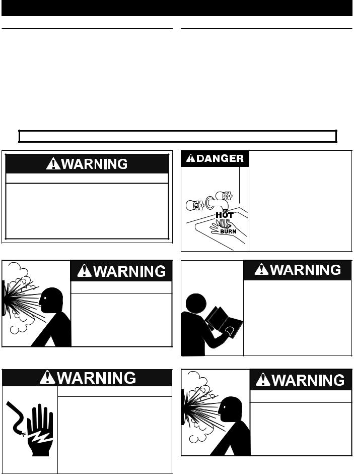
Water temperature over 125°F (52°C) can cause severe burns instantly resulting in severe injury or death.
Children, the elderly and the physically or mentally disabled are at highest risk for scald injury.
Feel water before bathing or showering.
Temperature limiting devices such as mixing valves must be installed when required by codes and to ensure safe temperatures at fixtures.
Read and understand this instruction manual and the safety messages herein before installing, operating or servicing this water heater.
Failure to follow these instructions and safety messages could result in death or serious injury.
This manual must remain with the water heater.
Electrical Shock Hazard
•Turn off power to the water heater before performing any service.
•Label all wires prior to disconnecting when performing service. Wiring errors can cause improper and dangerous operation.
•Verify proper operation after servicing.
•Failure to follow these instructions can result in personal injury or death.
Explosion Hazard
 Overheated water can cause water tank explosion.
 Properly sized temperature and pressure relief valve must be installed in the opening provided on connected storage tanks.
5
INTRODUCTION
Thank You for purchasing this heat pump water heater. Properly installed and maintained, it should give you years of trouble free service.
Abbreviations found In this Instruction Manual include:
•HPWH - Heat Pump Water Heater
•ANSI - American National Standards Institute
•ASME - American Society of Mechanical Engineers
•NEC - National Electrical Code
•NFPA - National Fire Protection Association
•AHRI - Air-conditioning, Heating and Refrigeration Institute
QUALIFICATIONS
QUALIFIED INSTALLER OR SERVICE AGENCY:
Installation and service of this water heater requires ability equivalent to that of a Qualified Agency (as defined by ANSI below) in the field involved. Installation skills such as plumbing, electrical supply are required in addition to electrical testing skills when performing service.
This heat pump water heater contains R-134a refrigerant and is regulated as a stationary refrigeration appliance under Section 608 of the Clean Air Act. Servicing of the refrigeration circuit must only be performed by agencies or individuals possessing Type II or Universal certification as defined in Section 608 of the Clean Air Act.
ANSI Z223.1 2006 Sec. 3.3.83: “Qualified Agency” - “Any individual, firm, corporation or company that either in person or through a representative is engaged in and is responsible for (a) the installation, testing or replacement of gas piping or (b) the connection, installation, testing, repair or servicing of appliances and equipment; that is experienced in such work; that is familiar with all precautions required; and that has complied with all the requirements of the authority having jurisdiction.”
PREPARING FOR THE INSTALLATION
Read and understand this instruction manual and the safety messages herein before installing, operating or servicing this water heater.
Failure to follow these instructions and safety messages could result in death or serious injury.
This manual must remain with the water heater.
1.Read the “General Safety Information” section of this manual first and then the entire manual carefully. If you don’t follow the safety rules, the heat pump water heater may not operate safely. It could cause DEATH, SERIOUS BODILY INJURY AND/OR PROPERTY DAMAGE.
This manual contains instructions for the installation, operation, and maintenance of the heat pump water heater (HPWH). It also contains warnings throughout the manual that you must read and be aware of. All warnings and all instructions are essential to the proper operation of the HPWH and your safety. READ THE ENTIRE MANUAL
BEFORE ATTEMPTING TO INSTALL OR OPERATE THIS WATER HEATING APPLIANCE.
Detailed installation diagrams are in this manual. These diagrams will serve to provide the installer with a reference for the materials and suggested methods of piping. IT IS NECESSARY THAT ALL WATER PIPING AND THE ELECTRICAL WIRING BE INSTALLED AND CONNECTED AS SHOWN IN THE DIAGRAMS.
Particular attention should be given to the installation of the system (tank) temperature control. See page 19.
Electrical Shock Hazard
•Turn off power to the water heater before performing any service.
•Label all wires prior to disconnecting when performing service. Wiring errors can cause improper and dangerous operation.
•Verify proper operation after servicing.
•Failure to follow these instructions can result in personal injury or death.
Be sure to turn off power when working on or near the electrical system of the heat pump. Never touch electrical components with wet hands or when standing in water.
When replacing fuses always use the correct size for the circuit. See Unit Wiring Diagrams-Fuse Sizes, pages 32-36.
The principal components of the HPWH are identified in the Features And Components section of this manual on page 8. The rating label on the HPWH also provides useful information. These references should be used to identify the heat pump, its components and optional equipment.
2.The installation must conform with these instructions and the local code authority having jurisdiction and the requirements of the power company. In the absence of local codes, the installation must comply with the latest editions of the National Electrical Code, ANSI/NFPA 70 or the Canadian Electrical Code CSA C22.1. The National Electrical Code may be ordered from: National Fire Protection Association, 1 Batterymarch Park, Quincy, MA 02269. The Canadian Electrical Code is available from the Canadian Standards Association, 8501 East Pleasant Valley Road, Cleveland, OH 44131.
3.If after reading this manual you have any questions or do not understand any portion of the instructions DO NOT proceed with the installation. Call the toll free number listed on the back cover of this manual for technical assistance.
4.In order to expedite your request, please have full model and serial number available for the technician.
5.Carefully consider your intended placement and location for the HPWH. See Locating The Water Heater on page 10
6.Installation and service of this HPWH requires ability equivalent to that of a licensed tradesman or QualifiedAgency in the field involved. See Qualifications on page 6.
7.For installation in California the HPWH appliance must be braced or anchored to avoid falling or moving during an earthquake. Instructions may be obtained from California Office of the State Architect, 1102 Q Street, Suite 5100, Sacramento, CA 95811.
6

8.Ensure the power supply voltage and phase at the job site matches the power requirements on the HPWH rating label before installation begins. Energizing the HPWH with the wrong voltage or phase will cause permanent damage to the unit.
PRINCIPLE OF OPERATION
The appliances covered by this Instruction Manual are commercial air-to-water heat pump water heaters (HPWH).
Operation of the HPWH is similar to that of a package air conditioning system though the HPWH is designed for indoor installation only. The primary difference in operation is that the HPWH unit utilizes the heat removed from the conditioned space to heat water where package air conditioning systems discard this heat outdoors. Recovering and using this waste heat increases the overall energy efficiency of the building.
THE REFRIGERATION CYCLE
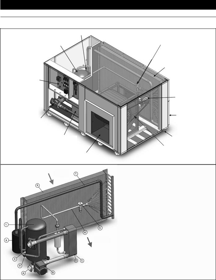
Refer to Figure 1 on page 8 for the location of components mentioned in this section.
Refrigerant is circulated through the refrigeration circuit by a Compressor (1). The refrigerant is a high temperature high pressure gas when it leaves the compressor. Refrigerant flows from the compressor through the Hot Gas Line (2) to the
Condenser (3).
The condenser is a refrigerant-to-water heat exchanger with two circuits, refrigerant flows through one circuit and water through the other. The high temperature refrigerant gas transfers its heat to the water flowing through the condenser. As the refrigerant gas cools inside the condenser it changes state (condenses) from a gas to a liquid. A Water Pump (B) circulates water through the condenser.
Refrigerant leaving the condenser is a medium temperature high pressure liquid. It flows through the Liquid Line (4) to the Thermostatic Expansion Valve (5). The thermostatic expansion valve (TXV) regulates the flow of refrigerant into the Evaporator
(6). The evaporator is a tube-and-fin constructed coil. It is an air- to-refrigerant heat exchanger with refrigerant flowing through the tubes and air flowing across the fins.
The Blower moves ambient air from the installed space or air ducted to the HPWH from another location across the fins of evaporator coil. The refrigerant absorbs heat from the air in the evaporator. The refrigerant changes state (boils/evaporates) from a liquid state back into a gas (vapor) in the evaporator.
The refrigerant flows out of the evaporator through the Suction Line (7) and into the Accumulator (8). The accumulator traps any liquid refrigerant the evaporator is unable to vaporize during low temperature operating conditions. The accumulator prevents liquid refrigerant from entering the compressor where it could damage internal components.
Low temperature low pressure refrigerant gas (vapor) is drawn out of the accumulator by the compressor. The compressor increases the pressure and temperature of the refrigerant gas circulating it to the condenser again where the refrigeration cycle starts over or continues.
AIR TEMPERATURE RANGE
The entering air temperature operating range for the HPWH is 50°F to 95°F (10°C to 35°C).
When the HPWH is operating properly the air temperature drop through the evaporator (heat exchanger) will be approximately 12°F to 20°F (7°C to 11°C).
WATER TEMPERATURE RANGE
The inlet (entering) water temperature operating range for the HPWH is 50°F to 140°F (10°C to 60°C).
When the HPWH is operating properly the water temperature rise through the condenser (heat exchanger) will be approximately 8°F to 12°F (4°C to 7°C).
REFRIGERANT CHARGE
The HPWH is factory-charged with R-134a refrigerant. The refrigerant charge is weighed in at the factory. See Table 9 on page 28. It should not be necessary to add or remove refrigerant during installation or start up.
EQUIPMENT DISPOSAL
This heat pump water heater contains R-134a refrigerant and is regulated as a stationary refrigeration appliance under Section 608 of the Clean Air Act. Disposal of this unit must be performed in accordance with the provisions in Section 608 of the Clean Air Act and any state or local regulations that may also apply. See Qualifications on page 6.
7
FEATURES AND COMPONENTS
PRODUCT ILLUSTRATIONS
ACCUMULATOR |
|
|
THERMOSTATIC |
COMPRESSOR |
EXPANSION VALVE (TXV) |
|
EVAPORATOR COIL |
|
(HEAT EXCHANGER) |
|
(AIR TO REFRIGERANT) |
CONTROL |
|
PANEL |
|
|
BLOWER |
|
MOTOR |
|
RETURN AIR |
WATER |
INLET |
PUMP |
(AIR FILTERS) |
CONDENSER |
CONDENSATE |
(HEAT EXCHANGER) |
DRAIN |
(REFRIGERANT TO WATER) |
BLOWER |
SUPPLY AIR |
|
OUTLET |
|
WARM RETURN
AIR IN
COOL SUPPLY
AIR OUT
COMPONENT REFRIGERATION CIRCUIT |
REFRIGERANT STATE |
|
1) |
COMPRESSOR |
GAS |
2) |
HOT GAS LINE |
GAS |
3) |
CONDENSER / HEAT EXCHANGER |
GAS TO LIQUID |
4) |
LIQUID LINE |
LIQUID |
5) |
THERMOSTATIC EXPANSION VALVE (TXV) |
LIQUID |
6) |
EVAPORATOR |
LIQUID TO GAS |
7) |
SUCTION LINE |
GAS |
8) |
ACCUMULATOR |
GAS / LIQUID |
COMPONENT WATER CIRCUIT
A)WATER INLET
B)WATER PUMP
C)HEAT EXCHANGER / CONDENSER
D)WATER OUTLET
Figure 1
8

ROUGH IN DIMENSIONS
Figure 2
PERFORMANCE SPECIFICATIONS
TABLE 1
|
|
PERFORMANCE |
|
|
|
|
DIMENSIONS |
|
|
|
||||
|
|
|
|
|
|
AIR |
WATER |
|
|
|
|
|
|
|
MODEL |
WATER |
COOLING |
|
INLET |
|
|
|
|
WEIGHT |
|||||
HEATING |
|
VOLUME |
FLOW |
OUTLET |
WIDTH |
DEPTH |
HEIGHT |
|
||||||
NUMBER |
CAPACITY |
COP |
D |
(LBS) |
||||||||||
(CFM) |
(GPM) |
|||||||||||||
|
CAPACITY |
|
|
WATER |
A |
B |
C |
|
||||||
|
kW |
Btu/hr* |
Btu/hr |
Tons |
|
|
|
(FPT) |
|
|
|
|
|
|
AWH-35 |
10.4 |
35,500 |
27,500 |
2.3 |
3.9 |
1040 |
7 |
1.0” |
40” |
26” |
24.75” |
7" |
315 |
|
AWH-55 |
17.0 |
58,000 |
45,500 |
3.8 |
4.1 |
1650 |
11 |
1.0” |
47” |
32” |
28.5” |
7" |
405 |
|
AWH-75 |
22.3 |
76,000 |
59,000 |
4.9 |
3.9 |
2150 |
15 |
1.5” |
57” |
32” |
28.5” |
7" |
485 |
|
AWH-100 |
28.7 |
98,000 |
78,000 |
6.5 |
4.2 |
3200 |
20 |
1.5” |
63” |
38” |
42.5” |
8" |
660 |
|
AWH-115 |
33.1 |
113,000 |
89,000 |
7.4 |
4.2 |
3200 |
23 |
1.5” |
63” |
38” |
42.5” |
8" |
665 |
|
AWH-140 |
41.6 |
142,000 |
110,000 |
9.2 |
3.9 |
3800 |
28 |
2.0” |
63” |
38” |
42.5” |
8" |
725 |
|
AWH-170 |
50.1 |
171,000 |
133,000 |
11.1 |
3.9 |
4900 |
34 |
2.0” |
75” |
46” |
42.5” |
8" |
880 |
|
|
|
|
|
|
|
|
|
|
|
|
|
|
|
|
All dimensions are in inches. Weights are approximate shipping weights.
*Performance rating at 75ºF Entering Air Temperature and 55% Relative Humidity, 100ºF Entering Water Temperature. ** Blower design at 0.35” external static pressure.
C. O. P. = Coefficient Of Performance
All models standard 208/230 VAC, 3Ø, 60 Hz Optional 460 VAC, 3Ø, 60 Hz
Optional 208/230 VAC, 1Ø, 60 Hz available on AWH-35 and AWH-55 only
9

INSTALLATION REQUIREMENTS
Readallinstallationrequirementsinthismanualbeforeinstallation begins. The installation must conform to these instructions and all local and national code authority having jurisdiction.
Costs to diagnose, perform service and repair damage caused by installation errors are not covered under the limited warranty.
Costs to correct installation errors are not covered under the limited warranty.
WATER TEMPERATURE
MAXIMUM SYSTEM TEMPERATURE
The HPWH units covered in this manual are capable of maintaining a maximum system/storage tank temperature of 140°F (60°C). Some commercial water heating applications may require higher temperatures. Install a booster water heater downstream from the storage tank for temperatures above 140°F (60°C). See Figure 8 on page 18.
INLET & OUTLET WATER TEMPERATURE
The inlet (entering) water temperature operating range for the HPWH is 50°F to 140°F (10°C to 60°C). The water temperature rise (Delta T - ∆T) through the condenser (heat exchanger) will be approximately 8°F to 12°F (4°C to 7°C).
Outlet water temperatures up to 152°F (67°C) are possible during normal operation. Exposure to water temperatures this high can cause serious bodily injury or death. See Mixing Valves and Table 5 on page 14.
Service & Installation Notes:
If the inlet (entering) water temperature is outside the operating temperature range for extended periods the control system may lock out on high or low refrigerant pressure switch events/trips.
When the control system locks out on a refrigerant pressure switch event the compressor will stop running, the blower and circulation pump (on models equipped with factory installed pump) will continue to operate. This is a hard lock out condition. The control system is manually reset by cycling power to the HPWH off and then on again.
The tank thermostat must not be set any higher than 140°F (60°C) to prevent control system lock outs.
Ground water temperatures can fall below 50°F (10°C) for extended periods during winter months in many regions. For this reason the cold water supply lines and should not be connected directly to the HPWH inlet or T fitted into the inlet (return) water piping. The cold water supply lines should be connected directly to the storage tank only. See the Piping Diagrams on page 41 in this manual for more information.
AIR TEMPERATURE
ENTERING AIR TEMPERATURE
The return (entering) air temperature range of operation for the unit is 50° - 95°F (10°C to 35°C). The air temperature drop (Delta T - ∆T) through the evaporator (heat exchanger) will be approximately 12°F to 20°F (7°C to 11°C).
If the entering air temperature is outside this operating range the HPWH unit’s Ambient Air Limit Thermostat will discontinue heating operation until the entering air temperature returns to this operating range. See Figure 15 on page 37.
High Ambient Air Kits are available that will allow the unit to operate with entering air temperatures up to 120°F (49°C). These accessory kits must be installed if entering air temperatures exceed 95°F (35°C) for extended periods.
Contact your local distributor or call the technical support phone number listed on the back cover of this manual for more information on ordering one of these accessory kits.
Service & Installation Notes:
When the High Ambient Air kit is installed the heating stage set point on the Ambient Air Limit thermostat must be raised to 120°F (49°C) to allow heating operation up to this temperature.
LOCATING THE WATER HEATER
CAUTION
PROPERTY DAMAGE!
•All water heaters eventually leak.
•Do not install without adequate drainage.
INDOOR INSTALLATION ONLY
The HPWH unit is designed for indoor installation only.
Carefully choose a location for the HPWH unit. Placement is a very important consideration for optimal performance and safety.
Locate the HPWH near a floor drain. The unit should be located in an area where leakage from the HPWH unit or the storage tank it is connected to will not result in damage to the area adjacent to the water heater or to lower floors of the structure. See Unit Placement on page 16.
FREEZING TEMPERATURES
The HPWH unit must not be installed in space where freezing temperatures will occur. Exposure to freezing ambient temperatures below 32°F (0°C) may result in severe damage to internal components. Damage caused by exposure to freezing temperatures is not covered under the limited warranty.
COASTAL REGIONS
When the HPWH will be installed within 5 miles of a seacoast the optional Corrosive Duty Package is required. The corrosive duty packageincludes a 316 stainless steelcabinet and a phenolic coating applied to the evaporator and blower. Damage caused to units not equipped with the corrosive duty package in coastal regions is not covered under the limited warranty.
HEAT SOURCE
The HPWH unit should be located where there is an adequate source of ambient heat and where the cooling benefit can be utilized when possible.
If installation in a space with an adequate heat source is not possible the HPWH unit can be ducted to/from another space such as a boiler room or to the outdoors where sufficient heat is available. See Air Flow and Ducting on page 19.
CONDITIONED SPACE
When installed in a conditioned space ducting supply (outlet) air to an alternate location may be necessary to avoid over-cooling of the space where the HPWH is installed or provide spot cooling in areas for comfort and/or to offset cooling load. See Building Air Pressure, Air Flow and Ducting on page 19.
10
UNCONDITIONED SPACE
When installed in an unconditioned space ducting return (inlet) air from an alternate location may be necessary to access an adequate or greater source of heat for optimal efficiency. See Building Air Pressure, Air Flow and Ducting on page 19.
CLEARANCES
To ensure optimal performance a minimum of 30 inches clearance is required from the back, left and right sides of the HPWH unit and any wall obstruction. A minimum of 36 inches clearance on the front of the unit for access to the control box. See Figure 3
When installed on an equipment pad the HPWH must be level and elevated at least 6” above floor to avoid dust and debris and permit connection of the condensate line and trap.
Figure 3
TABLE 2
ELECTRICAL REQUIREMENTS
CAUTION
CORRECT POWER SUPPLY!
•Ensure the power supply at the job site matches the voltage and phase listed on the HPWH rating label before connecting power to the HPWH unit.
•Energizing the HPWH with the wrong voltage or phase will cause permanent damage to the HPWH unit.
•Damage caused to the HPWH as the result of applying the wrong voltage or phase is not covered under the limited warranty.
Ensure the power supply voltage and phase at the job site matches the power supply ratings listed on the HPWH rating label BEFORE INSTALLATION BEGINS.
The installation must conform with these instructions and the local code authority having jurisdiction and the requirements of the power company. In the absence of local codes, the installation must comply with the current editions of the National Electrical Code, ANSI/NFPA 70 or the Canadian Electrical Code CSA C22.1.
Voltage applied to the HPWH should not vary more than +5% to -10% of the voltage requirement listed on the HPWH rating label for satisfactory operation.
VOLTAGE & AMPERAGE RATINGS
MODEL |
VOLTS/PHASE/HZ |
COMPRESSOR |
|
|
BLOWER MOTOR |
PUMP (230 VAC 1Ø)* |
MCA |
MFS |
||||
RLA |
LRA |
MCC |
|
FLA |
HP |
FLA |
HP |
|||||
AWH-35 |
208-230/1/60 |
|
18.60 |
100.00 |
29.00 |
|
3.60 |
1/2 |
0.88 |
1/8 |
28 |
45 |
AWH-35 |
208-230/3/60 |
|
10.90 |
77.00 |
17.00 |
|
2.40 |
1/2 |
0.88 |
1/8 |
17 |
25 |
AWH-35 |
460/3/60 |
|
5.40 |
39.00 |
8.50 |
|
1.20 |
1/2 |
0.88 |
1/8 |
9 |
12 |
AWH-55 |
208-230/1/60 |
|
27.90 |
175.00 |
43.50 |
|
5.30 |
3/4 |
0.88 |
1/8 |
42 |
60 |
AWH-55 |
208-230/3/60 |
|
19.90 |
115.00 |
31.00 |
|
3.00 |
3/4 |
0.88 |
1/8 |
29 |
45 |
|
|
|
|
|
|
|
|
|
|
|
|
|
AWH-55 |
460/3/60 |
|
8.70 |
63.00 |
13.50 |
|
1.50 |
3/4 |
0.88 |
1/8 |
13 |
20 |
AWH-75 |
208-230/3/60 |
|
24.00 |
196.00 |
37.50 |
|
3.60 |
1 |
0.88 |
1/8 |
35 |
50 |
AWH-75 |
460/3/60 |
|
11.50 |
100.00 |
18.00 |
|
1.80 |
1 |
0.88 |
1/8 |
17 |
25 |
AWH-100 |
208-230/3/60 |
|
28.20 |
225.00 |
44.00 |
|
3.60 |
1 |
0.88 |
1/8 |
40 |
60 |
AWH-100 |
460/3/60 |
|
14.10 |
114.00 |
22.00 |
|
1.80 |
1 |
0.88 |
1/8 |
20 |
30 |
AWH-115 |
208-230/3/60 |
|
35.30 |
239.00 |
55.00 |
|
3.60 |
1 |
1.00 |
1/6 |
49 |
80 |
AWH-115 |
460/3/60 |
|
17.90 |
125.00 |
28.00 |
|
1.80 |
1 |
1.00 |
1/6 |
25 |
40 |
AWH-140 |
208-230/3/60 |
|
48.10 |
300.00 |
75.00 |
|
4.80 |
1 1/2 |
2.50 |
1/2 |
68 |
110 |
AWH-140 |
460/3/60 |
|
21.80 |
150.00 |
34.00 |
|
2.40 |
1 1/2 |
2.50 |
1/2 |
31 |
50 |
AWH-170 |
208-230/3/60 |
|
52.60 |
340.00 |
82.00 |
|
6.20 |
2 |
2.50 |
1/2 |
75 |
125 |
AWH-170 |
460/3/60 |
|
25.60 |
173.00 |
40.00 |
|
3.10 |
2 |
2.50 |
1/2 |
37 |
60 |
|
|
|
|
|
|
|
|
|
|
|
||
*460 VAC models factory-equipped with step down transformer for 230 VAC pump |
|
|
|
|
|
|||||||
Abbreviations: |
|
|
|
|
|
|
|
|
|
|
|
|
RLA = Running Load Amps; |
LRA = Locked Rotor Amps; |
|
MCC = Maximum Continuous Current; |
|
|
|
||||||
FLA = Full Load Amps; |
MCA = Minimum Circuit Ampacity; |
|
MFS = Maximum Fuse Size |
|
|
|
|
|||||
11
MINIMUM CIRCUIT AMPACITY & MAXIMUM FUSE SIZE
Electrical Shock Hazard
•Before removing any access panels or servicing the water heater, make sure the electrical supply to the water heater is turned “OFF.”
•Failure to do this could result in death, serious bodily injury, or property damage.
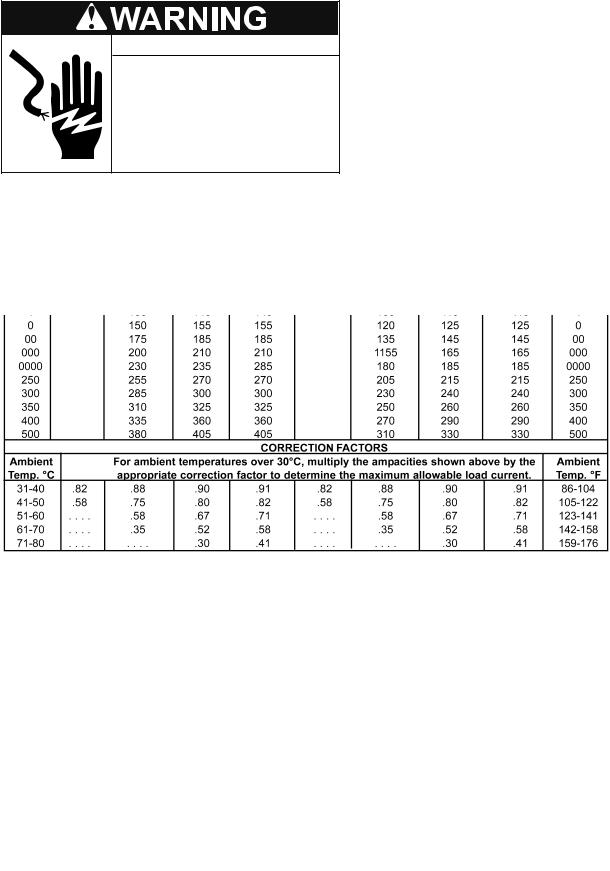
MINIMUM WIRE SIZE
Allowable Ampacities of Insulated Conductors
Table 2 on page 11 provides the MCA (Minimum Circuit Ampacity) and MFS (Maximum Fuse Size). Use MCA to select the minimum field wires size to power the unit and MFS to select the maximum fuse size for over current protection as follows:
MCA = C x 1.25 + M + P
MFS = C x 2.25 + M + P
Where:
C - Compressor RLA
M - Blower Motor FLA
P - Pump FLA
Single-phase heat pump water heaters are two wire circuits. Three-phase heaters are three wire circuits. In addition to the foregoing, a grounded conductor is required. Not more than three conductors in raceway, cable, or earth (directly buried), based on ambient temperature of 30°C (86°F)
TABLE 3
+The load current rating and the overcurrent protection for these conductors shall not exceed 15 amperes for 14 AWG. 20 amperes for 12 AWG and 30 amperes for 10 AWG copper; or 15 amperes for 12 AWG and 25 amperes for 10 AWG aluminum and copper-clad aluminum.
*For dry locations only. See 75°C column for wet locations.
12
WATER PIPING
Read all installation requirements in this manual before installation begins.
The water piping installation must conform to these instructions and to all local and national code authority having jurisdiction.
Costs to diagnose, perform service and repair damage caused by installation errors are not covered under the limited warranty.
Costs to correct installation errors are not covered under the limited warranty.
MAXIMUM PIPE LENGTH
Factory installed pumps will provide the specified water flow for up to a total of 50 equivalent feet of water piping between the HPWH and the storage tank. Example: 25 equivalent feet of inlet (return) piping and 25 equivalent feet of outlet (supply) piping.
Exceeding these maximum lengths will cause the unit to malfunction and control system lock outs.
MINIMUM PIPE SIZE
The inlet (return) and outlet (supply) water piping installed between the HPWH unit and the storage tank must not be smaller than the water connection sizes on the HPWH. See Table 4 for water line connection sizes and water flow rates.
Water line sizing is a critical installation requirement. Installing undersized water piping between the storage tank and the HPWH unit will cause insufficient water flow and will have an adverse impact on performance and equipment life.
TABLE 4
WATER CONNECTIONS AND FLOW
UNIT |
GPM |
LPM |
CONNECTION SIZE (INCH) |
AWH-35 |
7 |
27 |
1 |
AWH-55 |
11 |
42 |
1 |
AWH-75 |
15 |
57 |
1.5 |
AWH-100 |
20 |
76 |
1.5 |
AWH-115 |
23 |
87 |
1.5 |
AWH-140 |
28 |
106 |
2 |
AWH-170 |
34 |
129 |
2 |
PIPE SUPPORT
All water piping must be properly supported per local code requirements.
PIPE INSULATION
All piping installed between the HPWH unit and the storage tank must be insulated.
COLD WATER SUPPLY
Cold water supply lines should not be connected directly to the HPWH inlet or T fitted into the inlet (return) water piping. The cold water supply lines should be connected directly to the storage tank only. See Inlet & Outlet Water Temperature on page 10 and Figure 7 and Figure 8 on page 18.
WATER PRESSURE
System water pressure should be maintained between 40 and 60 PSI. Local code may require, and the manufacturer recommends, installing a pressure reducing valve (PRV) in the cold water supply to the building to maintain consistent water pressure.
CLOSED WATER SYSTEMS
Water supply systems may, because of code requirements or such conditions as high line pressure, among others, have installed devices such as pressure reducing valves, check valves, and back flow preventers. Devices such as these cause the water system to be a closed system.
THERMAL EXPANSION
As water is heated, it expands (thermal expansion). In a closed system the volume of water will grow when it is heated. As the volume of water grows there will be a corresponding increase in water pressure due to thermal expansion. Thermal expansion can cause premature failure (leakage) of storage tanks, water heaters and HPWH components such as the condenser. Leakage caused by thermal expansion is not covered under the HPWH limited warranty.
Thermal expansion can also cause intermittent TemperaturePressure Relief Valve operation: water discharged due to excessive pressure build up. The Temperature-Pressure Relief Valve is not intended for the constant relief of thermal expansion.
A properly sized thermal expansion tank must be installed on all closed systems to control the harmful effects of thermal expansion. Contact a local plumbing service agency to have a thermal expansion tank installed on all closed water systems.
MIXING VALVES
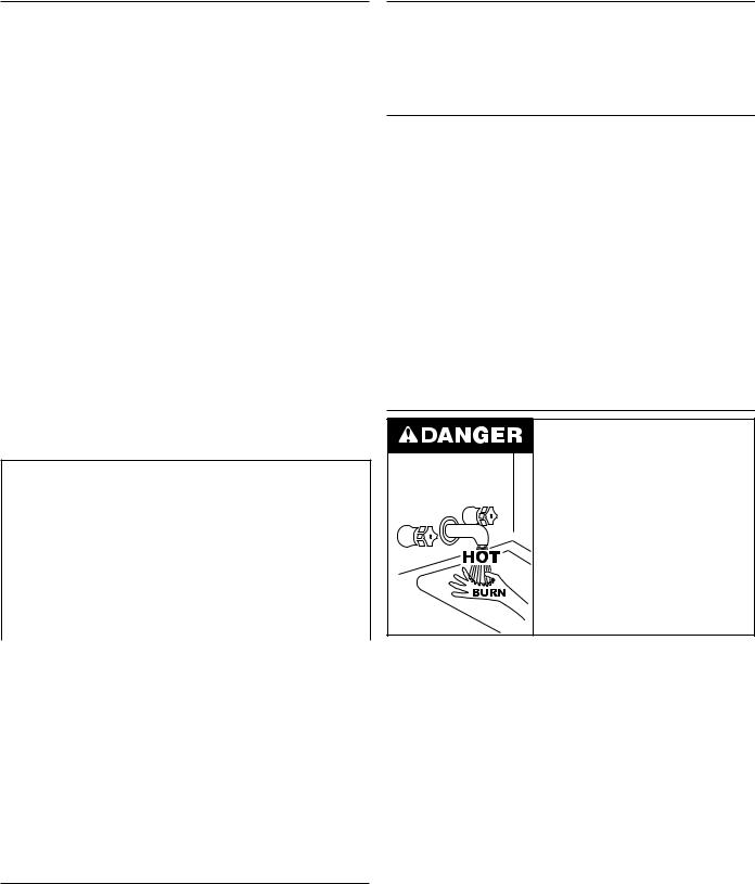
Water temperature over 125°F (52°C) can cause severe burns instantly resulting in severe injury or death.
Children, the elderly and the physically or mentally disabled are at highest risk for scald injury.
Feel water before bathing or showering.
Temperature limiting devices such as mixing valves must be installed when required by codes and to ensure safe temperatures at fixtures.
Water heated to a temperature which will satisfy clothes washing, dish washing, and other sanitizing needs can scald and cause permanent injury upon contact. See Table 5.
Some people are more likely to be permanently injured by hot water than others. These include the elderly, children, the infirm and the physically/mentally disabled. The Table below shows the approximate time-to-burn relationship for normal adult skin. If anyone using hot water provided by the water heater being installed fits into one of these groups or if there is a local code or state law requiring a certain water temperature at the point of use, then special precautions must be taken.
In addition to using the lowest possible temperature setting that satisfies the demand of the application a Mixing Valve should be installed upstream from the building fixtures or at the hot water taps to further reduce system water temperature.
Mixing valves are available at plumbing supply stores. Consult a Qualified Installer or Service Agency. Follow the mixing valve manufacturer’s instructions for installation of the valves.
13
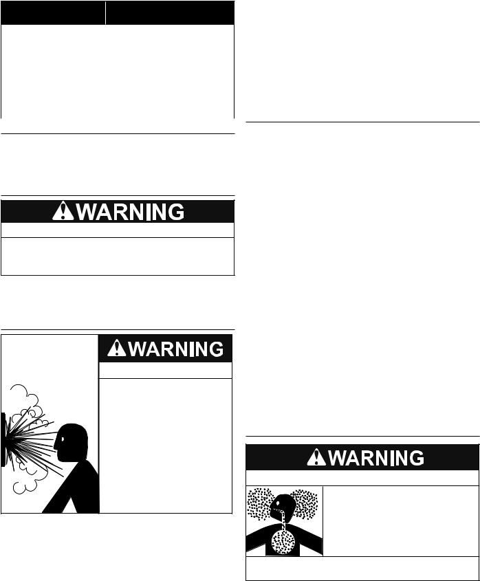
TABLE 5
Water Temperature |
Time to Produce 2nd & 3rd |
|
Degree Burns on Adult Skin |
||
|
180°F (82°C) |
Nearly instantaneous |
170°F (77°C) |
Nearly instantaneous |
160°F (71°C) |
About 1/2 second |
150°F (66°C) |
About 1-1/2 seconds |
140°F (60°C) |
Less than 5 seconds |
130°F (54°C) |
About 30 seconds |
120°F (49°C) |
More than 5 minutes |
CONDENSATE REMOVAL
The HPWH unit produces condensate which must be discharged. If there is no drain easily accessible, a condensate lift pump must be installed to discharge the condensate to a remote location. See Condensate Drain Line on page 18 for installation instructions.
CONTAMINATED WATER
Corrosive Chemical Hazard
•Connecting the heat pump to any system other than a water system may lead to premature corrosion of the unit's heat exchanger and void the unit warranty.
This HPWH unit must not be used to heat any fluid other than water. Corrosive chemicals must not be introduced into the waterways in this HPWH unit.
TEMPERATURE - PRESSURE RELIEF VALVE
Explosion Hazard
 Temperature-Pressure Relief Valve must comply with ANSI Z21.22CSA 4.4 and ASME code.
 Properly sized temperaturepressure relief valve must be installed in the designated opening in the storage tank.
 Can result in overheating and excessive tank pressure.
 Can cause serious injury or death.
This heat pump water heater should only be connected to a storage tank with a properly rated/sized and certified combination temperature - pressure relief valve. The valve must be certified by a nationally recognized testing laboratory that maintains periodic inspection of production of listed equipment of materials as meeting the requirements for Relief Valves for Hot Water Supply Systems, ANSI Z21.22 • CSA 4.4, and the code requirements of ASME.
WhentheHPWHunitisconnectedtoastoragetankatemperature and pressure relief valve must be installed in the designated opening for the T&P valve per the storage tank manufacturer’s requirements. The T&P valve’s Btu/hr rating must be equal to or greater than the total heating input rating of all water heaters
connected to the storage tank. If more than one water heating appliance is connected to the storage tank the aggregate total of all heating input ratings of all connected appliances must be factored when choosing a T&P valve for the storage tank.
The pressure rating of the T&P valve should always be rated equal to or below the working pressure rating of the storage tank or water heater, whichever rating is lower.
Contact the manufacturer of the storage tank for assistance in sizing of a temperature and pressure relief valve. Follow the storage tank manufacturer’s instructions regarding the proper installation of these products.
TANK SELECTION
The HPWH unit is not an instantaneous water heater and must be connected to a storage tank. Storage tank configurations must meet these criteria:
1.The HPWH must not be connected directly to a standard gas or electric water heater.
2.If the HPWH is connected to a used storage tank, the tank should be thoroughly cleaned of scale and sediment before the HPWH is installed.
3.Connection ports used on the storage tank must permit the recommended flow rate through HPWH. The connection ports used on the storage tank must not be smaller than the inlet outlet connection sizes on the HPWH unit. See Table 4 on page 13.
4.Water heated by the HPWH should be returned to the tank at a location that is above the level of the tank’s cold water inlet and/or the heat pump’s inlet source.
5.The HPWH unit’s inlet and outlet lines to the storage tank should be dedicated. Example: no other line (such as a building re-circulating loop or cold water supply) should be connected to the HPWH unit’s inlet or outlet water lines.
SOLAR TANKS
Solar tanks should be used with caution. Some solar tanks with top connections have dip tubes which may significantly reduce the efficiency performance of the HPWH unit.
Before using any solar tank in this application, contact your representative or call the toll free technical support number on the back cover of this manual for further assistance.
CONTAMINATED AIR
Breathing Hazard - Carbon Monoxide Gas
 Do not duct air from a garage or other space where potentially harmful fumes from solvents, chemicals or exhaust from automobiles are present into any other space in the building structure.
 Gas and carbon monoxide detectors are available.
Breathing carbon monoxide can cause brain damage or death. Always read and understand instruction manual.
The supply (outlet) air from a HPWH installed in a garage or a unit drawing return (inlet) air from a garage or any area where solvents or other chemicals that emit potentially harmful fumes are stored or automobiles are located must never be ducted to any other space inside the building structure. This would include all occupied and unoccupied spaces such as attics or basements.
14

Potentially harmful fumes and vapors could be introduced into occupied spaces. See Unit Placement on page 16.
STORAGE & HANDLING
HEAVY OBJECT!
All Heat Pump Water Heaters (HPWHs) covered by this manual are beyond the safe lifting weight for one person. Use proper conveyance equipment to move the unit for storage or during installation. Use OSHA approved safety equipment when moving the unit.
The heat pump water heaters covered in this manual are stationary refrigeration appliances. Careful handling is necessary to prevent internal damage.
•IMPORTANT: Do not remove, cover or deface any permanent instructions, wiring diagrams, labels, or the rating label from the outside cabinet or the inside panels on the HPWH unit.
•Do not tilt the unit beyond 45° at any time. All internal components are braced from the base of unit. Tilting may compromise the refrigeration piping inside unit and cause refrigerant leaks.
•Do not hoist the unit with chains or straps unless spreader bars are furnished and used as depicted in Figure 4 and Figure 5. The side panels and roof of the unit are not constructed to handle significant force from the sides or above.
•The HPWH unit is heaviest on the compressor side (left side when facing the front of the unit). See Figure 4 and Figure 6.
•When using a forklift to raise the HPWH unit ensure the forks are positioned correctly between the runners on the bottom of the HPWH unit. See Figure 6.
•The HPWH unit must be lifted from the front side only when using a forklift to raise the unit. See Figure 6.
 RIGGING
COMPRESSOR
SIDE SPREADER
BAR
FRONT
 SUPPORT BARS
Figure 4
SPREADER
BAR
SIDE
Figure 5
Figure 6
STORAGE RECOMMENDATIONS
The HPWH units should be stored indoors. Do not stack units or stack other construction materials on the units while in storage.
The HPWH units contain electrical/electronic components and should only be stored in conditions between 0ºF to 110°F (-17°C to 43°C) and 5 to 95 percent relative humidity. Electrical components are not moisture-tolerant.
NOTE: The limited warranty does not cover damage to the unit or controls due to negligence during storage.
15
 Loading...