


On-Demand Water Heater
Installation Manual and Owner’s Guide
 ANSI Z21.10.3 and CSA 4.3
Models
• 110U Indoor (T-KJr2U-IN) • 110U Outdoor (T-KJr2U-OS)
•310U Indoor (T-K4U-IN) • 310U Outdoor (T-K4U-OS)
•510U Indoor (T-D2U-IN) • 510U Outdoor (T-D2U-OS)
510U (T-D2U) models only
Gas Tankless Water HeaterTM
Suitable for potable water heating and space-heating* * Please refer to local codes for space-heating compliance.
FEATURING
•ENDLESS HOT WATER
•ON-DEMAND USAGE
•COMPACT, SPACE SAVING
•ENERGY CONSERVATION
•COMPUTERIZED SAFETY
•NO PILOT LIGHT
•Satisfies the 2012 SCAQMD Rule 1146.2 for Ultra-Low NOx Emissions
•EASY-LINK SYSTEM AND
MULTI-UNIT SYSTEM
(510U (T-D2U) models only)
If the information in these instructions is not followed exactly, a fire or explosion may
WARNING resultcausingpropertydamage, personal injury or death.
-Do not store or use gasoline or other flammable vapors and liquids in the vicinity of this or any other appliance.
-WHAT TO DO IF YOU SMELL GAS
•Do not try to light any appliance.
•Do not touch any electric switch, do not use any phone in your building.
•Immediately call your gas supplier from a neighbor's phone. Follow the gas supplier's instructions.
•If you cannot reach your gas supplier, call the fire department.
-Installation and service must be performed by a qualified installer, service agency or the gas supplier.
If you have any questions, please call or write to:
500 Tennessee Waltz Parkway
Ashland City, TN 37015
Toll Free: 1-877-737-2840

CONTENTS |
|
Installation Manual |
|
SPECIFICATIONS.......................................................................................................................... |
4 |
INTRODUCTION.......................................................................................................................... |
5 |
SAFETY GUIDELINES.................................................................................................................... |
6 |
INSTALLATION............................................................................................................................. |
7 |
General..................................................................................................................................... |
7 |
Clearances................................................................................................................................ |
9 |
Included Accessories............................................................................................................... |
9 |
Optional Items........................................................................................................................ |
9 |
WarningforInstallations.......................................................................................................... |
9 |
High-altitudeInstallations...................................................................................................... |
12 |
VentingInstructions............................................................................................................... |
13 |
Gassupplyandgaspipesizing............................................................................................... |
18 |
WaterConnections................................................................................................................ |
20 |
ElectricalConnections............................................................................................................ |
21 |
TemperatureRemoteController........................................................................................... |
22 |
Easy-linkSystem..................................................................................................................... |
25 |
Multi-UnitSystem.................................................................................................................. |
29 |
APPLICATIONS............................................................................................................................ |
30 |
INITIAL OPERATION................................................................................................................... |
32 |
Owner's Guide |
|
OPERATING SAFETY.................................................................................................................. |
34 |
NORMAL OPERATION............................................................................................................... |
36 |
General.................................................................................................................................. |
36 |
TemperatureSettings............................................................................................................. |
37 |
Flow....................................................................................................................................... |
40 |
Freezeprotectionsystem....................................................................................................... |
40 |
Maintenanceandservice....................................................................................................... |
41 |
UnitDrainingFilterCleaning.................................................................................................. |
41 |
TROUBLESHOOTING................................................................................................................... |
42 |
General................................................................................................................................... |
42 |
Error Codes........................................................................................................................... |
44 |
COMPONENTSDIAGRAM........................................................................................................... |
47 |
PARTS LIST................................................................................................................................. |
51 |
OUTPUT TEMPERATURE CHART................................................................................................ |
54 |
LIMITEDWARRANTY.................................................................................................................. |
55 |
2 Page

Installation Manual
Contents
Installation Manual
CONGRATULATIONS
Congratulations and thank you for choosing our tankless water heater. Before use, we recommend that you read through this safety manual carefully. Please refer to the back of the manual for details about the warranty. Keep this manual for future reference.
If you lose the manual, contact the manufacturer or your local distributor. When you call, please tell us the product name and the serial number of your unit written on the rating plate of the water heater.
3Page

Installation Manual
Specifications
SPECIFICATIONS
Model |
|
|
110U |
110U |
310U |
310U |
510U |
510U |
|
|
|
Indoor |
Outdoor |
Indoor |
Outdoor |
Indoor |
Outdoor |
||
|
|
|
(T-KJr2U-IN) (T-KJr2U-OS) (T-K4U-IN) (T-K4U-OS) (T-D2U-IN) (T-D2U-OS) |
||||||
Natural Gas Input |
BTU/h |
Min.: 15,000 |
Min.: 15,000 |
Min.: 15,000 |
|||||
(Operating Range) |
Max.: 140,000 |
Max.: 190,000 |
Max.: 199,000 |
||||||
|
|||||||||
Gas Connection |
|
|
|
3/4" NPT |
|
|
|||
Water Connections |
|
|
|
3/4" NPT |
|
|
|||
Water Pressure* |
psi |
|
|
15 - 150 (0.1 - 1) |
|
|
|||
(Mpa) |
|
|
|
|
|||||
Natural gas |
|
|
|
|
|
|
|
||
|
" W.C. |
|
|
Min. 5.0 (1.24 ) |
|
|
|||
Inlet Pressure |
(kPa) |
|
|
Max. 10.5 (2.61) |
|
|
|||
Manifold |
Natural |
" W.C. |
1.8 |
1.5 |
3.0 |
2.9 |
3.3 |
2.9 |
|
Pressure** |
Gas |
(Pa) |
(448) |
(373) |
(747) |
(722) |
(821) |
(722) |
|
Weight |
|
lbs. (kg) |
|
37 (16.9) |
|
39 (17.9) |
|||
Dimensions |
|
inch |
|
|
H 20.5 x W 13.8 x D 8.5 |
|
|
||
|
mm |
|
|
H 520 x W 351 x D 216 |
|
|
|||
|
|
|
|
|
|
||||
Ignition |
|
|
|
|
Electric Ignition |
|
|
||
Supply |
VAC / Hz |
|
|
120 / 60 |
|
|
|||
Operation |
W / A |
52.1 / 0.54 |
75.8 / 0.83 |
81.6 / 0.86 |
|||||
Standby |
W / A |
5.4 / 0.08 |
5.5 / 0.08 |
6.5 / 0.09 |
|||||
Electric Consumption Freeze- |
W / A |
131 / 1.1 |
131 / 1.1 |
132 / 1.1 |
|||||
Protection |
|
|
|
|
|
|
|
||
*40 psi or above is recommended for maximum flow.
** The Manifold Pressure is the factory setting and generally should not need adjustment.
NOTE:
•Check the rating plate to ensure this product matches your specifications.
•In accordance with ANSI Z21.10.3, CO emission does not exceed 400 PPM for normal input.
•The manufacturer reserves the right to discontinue, or change at any time, specifications or designs without notice and without incurring obligations.
4 Page

Installation Manual
Introduction
INTRODUCTION
•This manual provides information necessary for the installation, operation, and maintenance of the water heater.
•The model description is listed on the rating plate which is attached to the front panel of the water heater.
•Please read all installation instructions completely before installing this product.
•Ifyouhaveanyproblemsorquestionsregardingthisequipment,consultwiththemanufacturer or its local representative.
•This equipment is an on-demand, tankless water heater designed to efficiently supply endless hot water for your needs.
•The 110U Indoor (T-KJr2U-IN), 310U Indoor (T-K4U-IN) and 510U Indoor (T-D2U-IN) models are to be installed indoor (direct-vent convertible). The 110U Outdoor (T-KJr2U-OS), 310U Outdoor (T-K4U-OS) and 510U Outdoor (T-D2U-OS) models are to be only installed outdoor.
•The principle behind tankless water heaters is simple:
Exhaust vent collar
Heat exchanger
Flow adjustment valve |
Burners |
|
Computer board |
|
|
|
|
Gas valves |
Flow sensor |
|
|
Thermistor |
|
Fan motor |
|
|
|
|
Thermistor |
Gas inlet |
|
|
|
Hot water outlet |
Cold water inlet |
|
*This diagram illustrates tankless water heater design concepts only and does not accurately represent the water heater’s physical description.
1.A hot water tap is turned on.
2.Water enters the heater.
3.The water flow sensor detects the water flow.
4.The computer initiates the fan motor and sends a signal to the igniter to create an ignition spark.
5.The gas ignites and flames appear within the burner chamber.
6.Water circulates through the heat exchanger and then gets hot.
7.Using thermistors to measure temperatures throughout the water heater, the computer modulates the gas and water valves to ensure proper output water temperature.
8.When the tap is turned off, the unit shuts down.
5 Page
Installation Manual
Safety Guidelines
SAFETY GUIDELINES
SAFETY DEFINITION
Indicates an imminently hazardous situation which, if not avoided, will result in DANGER death or serious injury.
Indicates an imminently hazardous situation which, if not avoided, could result
in death or serious injury.
WARNING
Indicates an imminently hazardous situation which, if not avoided, could result CAUTION in minor or moderate injury.
GENERAL
1.Follow alllocalcodes,orintheabsenceoflocalcodes,followthemostrecentedition oftheNational Fuel Gas Code: ANSI Z223.1/NFPA 54 in the USA or CAN/CSA B149.1 Natural Gas Installation Code in Canada.
2.Properly ground the unit in accordance with all local codes or in the absence of local codes, with the National Electrical Codes: ANSI/NFPA 70 in the USA or CSA standard C22.1 Canada Electrical Code Part 1 in Canada.
3.Carefully plan where you intend to install the water heater. Please ensure:
•Your water heater will have enough combustible air and proper ventilation.
•Locate your heater where water leakage will not damage surrounding areas (please refer to p. 8).
4.Check the rating plate for the correct GAS TYPE, GAS PRESSURE, WATER PRESSURE and ELECTRIC RATING.
*If this unit does not match your requirements, do not install and consult with the manufacturer.
5.If any problem should occur, turn off all hot water taps and turn off the gas. Then call a trained technician or the Gas Company or the manufacturer.
•Water temperatures over 125 °F (52 °C) can cause severe burns instantly or
|
|
death from scalding. The water temperature is set at 120 °F (49 °C) from the |
|
|
factory to minimize any scalding risk. Before bathing or showering always |
|
|
check the water temperature. |
WARNING |
|
|
|
• |
Do not store or use gasoline or other flammables, vapors, or liquids in the |
|
|
vicinity of this appliance. |
|
• Do not reverse the water and/or gas connections as this will damage the gas |
|
|
|
valvesandcancausesevereinjuryordeath.Followthediagramonp.20when |
|
|
installing your water heater. |
|
• |
Do not use this appliance if any part has been in contact with or been |
|
|
immersed in water. Immediately call a licensed plumber, a licensed gas fitter, |
|
|
or a professional service technician to inspect and/or service the unit if |
|
|
necessary. |
|
• |
Do not disconnect the electrical supply if the ambient temperature will |
|
|
drop below freezing. The Freeze Prevention System only works if the unit |
|
|
has electrical power. The warranty will not be covered if the heat exchanger |
|
|
is damaged due to freezing. Refer to the section on the Freeze Prevention |
|
|
System on p. 39 for more information. |
6 Page

Installation Manual
Installation
INSTALLATION
GENERAL
1.Follow all local codes, or in the absence of local codes, follow the most recent edition of the National Fuel Gas Code: ANSI Z223.1/NFPA 54 in the USA or CAN/CSA B149.1 Natural Gas Installation Code in Canada.
2.Allgaswaterheatersrequirecarefulandcorrectinstallationtoensuresafeandefficientoperation.This manual must be followed exactly. Read the “Safety Guidelines” section.
3.The manifold gas pressure is preset at the factory. It is computer controlled and should not need adjustment.
4.Maintain proper space for servicing. Install the unit so that it can be connected or removed easily. Refer to the "Clearances" section on p. 9 for proper clearances.
5.The water heater must be installed in a location where the proper amount of combustible air will be available to it at all times without obstructions.
6.The electrical connection requires a means of disconnection, to terminate power to the water heater for servicing and safety purposes.
7.Do not install the unit where the exhaust vent is pointing into any opening in a building or where the noise may disturb your neighbors. Make sure the vent termination meets the required distance by local code from any doorway or opening to prevent exhaust from entering a building (refer to p. 14).
8.Particles from flour, aerosols, and other contaminants may clog the air vent or reduce the functions of the rotating fan and cause improper burning of the gas. Regularly ensure that the area around the unit is dustor debris-free; regular maintenance is recommended for these types of environment.
9.If you will be installing the water heater in a contaminated area with a high level of dust, sand, flour, aerosols or other contaminants/chemicals, they can become airborne and enter and build up within the fan and burner causing damage to the water heater.
10.For the 110U Indoor (T-KJr2U-IN), 310U Indoor (T-K4U-IN) and 510U Indoor (T-D2U-IN) models:
•These units may be converted to a direct-vent (sealed combustion) appliance by installing a direct-vent conversion kit Part No. 9007667005 (TK-TV10) which will bring in all required
combustible air from outside the building. When installing the direct-vent conversion kit, please follow all instructions included with the kit.
•If the water heater is used as a direct-vent appliance, the unit requires a 3 in. (76 mm) combustible air supply pipe. The intake pipe must be sealed airtight. Air supply pipe can be made of ABS, PVC, galvanized steel, corrugated aluminum, corrugated stainless steel or Category III stainless steel.
•Terminating the venting through a sidewall is recommended for the direct-vent system.
•Running the exhaust vent and the intake pipe parallel is recommended.
•Terminating the exhaust and intake on the same wall/surface is recommended. Terminating in the same pressure zone allows for pressure balancing, which prevents nuisance shutdowns.
11.Forthe110UOutdoor(T-KJr2U-OS),310UOutdoor(T-K4U-OS)and510UOutdoor(T-D2U-OS)models:
•To be installed outdoors and only in areas with mild, temperate climates.
7 Page
Installation Manual
Installation
WARNING
CAUTION
•Installation and service must be performed by a qualified installer (for example, a licensed plumber or gas fitter), otherwise the warranty will be
void.
•The installer (licensed professional) is responsible for the correct installation of the water heater and for compliance with all national, state/provincial, and local codes.
•The manufacturer does not recommend installing the water heater in a pit or location where gas and water can accumulate.
•Do not have the vent terminal pointing toward any operating window, door, or opening into a building.
•Do not install next to any source of airborne debris, such as a clothes dryer, that can cause debris to be trapped inside the combustion chamber,unless the system is direct-vented.
•The manufacturer does not recommend installing the water heater in an attic due to safety issues. If you install the water heater in an attic:
•Make sure the unit will have enough combustion air and proper ventilation.
•Keep the area around the water heater clean. When dust collects on the flame sensor, the water heater will shut down on an error code.
•If the above conditions cannot be met, use the direct vent conversion kit Part No. 9007667005 (TK-TV10).
•Place the unit for easy access for service and maintenance.
•A drain pan, or other means of protection against water damage, is required to be installed under the water heater in case of leaks.
•The warranty will not cover damage caused by water quality.
•Only potable water or potable water / glycol mixtures can be used with this water heater. Do not introduce pool or spa water, or any chemically treated water into the water heater.
•Water hardness levels must not exceed 7 grains per gallon (120 ppm) for single family domestic applications or more than 4 grains per gallon (70 ppm) for all other types of applications. Water hardness leads to scale formation and may affect / damage the water heater. Hard water scaling must be avoided or controlled by proper water treatment.
•Water pH levels must be between 6.5 and 8.5
•Well water must be treated.
•Do not install the unit where water, debris, or flammable vapors may get into the flue terminal.
•The manufacturer recommends using the direct vent kit when the water heater is installed in a beauty salon. Some chemicals used in a beauty salon may affect the flame sensor. Water heater may not work properly.
•Although the water heater is designed to operate with minimal sound, the manufacturer does not recommend installing the unit on a wall adjacent to a bedroom, or a room that is intended for quiet study or meditation, etc.
•Locate your heater close to a drain where water leakage will not do damage to surrounding areas. As with any water heating appliance, the potential for leakage at some time in the life of the product does exist. The manufacturer will not be responsible for any water damage that may occur. If you install a drainpanundertheunit,ensurethatitwillnotrestrictthecombustionairflow.
8 Page
Installation Manual
Installation
CLEARANCES
 Top
Top
Maintain all |
clearances |
around |
Side |
|
Black |
|
|
|
|||
the water heater. |
|
Front |
Side |
||
|
|
|
|
|
|
|
|
|
|
Bottom |
|
Model |
Top |
Bottom |
Front |
Back |
Sides |
110U Indoor (T-KJr2U-IN)* |
12 in. |
12 in. |
4 in.** |
0.5 in. |
2 in. |
310U Indoor (T-K4U-IN)* |
(305 mm) |
(305 mm) |
(102 mm) |
(13 mm) |
(51 mm) |
510U Indoor (T-D2U-IN)* |
|
|
|
|
|
110U Outdoor (T-KJr2U-OS) |
36 in. |
12 in. |
24 in. |
0.5 in. |
2 in. |
310U Outdoor (T-K4U-OS) |
(914 mm) |
(305 mm) |
(610 mm) |
(13 mm) |
(51 mm) |
510U Outdoor (T-D2U-OS) |
|
|
|
|
|
*Standard indoor installations and direct-vent indoor installations have the same clearances. **24 inch recommended for maintenance.
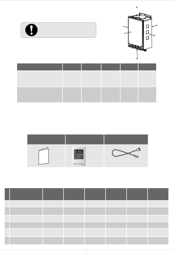
INCLUDED ACCESSORIES
Check that these items below are included with the water heater.
Installation Manual |
Temperature |
Communication Cable |
and Owner’s Guide |
Remote Controller Kit* 510U (T-D2U) models only |
|
Qty: 1 |
Qty: 1 |
Qty: 1 |
*Refer to the p.22.
OPTIONAL ITEMS
# |
|
110U |
110U |
310U |
310U |
510U |
510U |
Model |
Indoor |
Outdoor |
Indoor |
Outdoor |
Indoor |
Outdoor |
|
|
|
(T-KJr2U-IN) |
(T-KJr2U-OS) (T-K4U-IN) |
(T-K4U-OS) |
(T-D2U-IN) |
(T-D2U-OS) |
|
1. |
Backflow Preventer |
|
|
|
|
|
|
2. |
Direct-Vent |
|
|
|
|
|
|
Conversion Kit |
|
|
|
||||
3. |
Pipe covers |
|
|
|
|||
4. |
Recess box |
|
|
|
|
|
|
5. |
T-Vent Wall Thimble |
|
|
|
|
|
|
with Termination |
|
|
|
||||
6. |
Direct-Vent Concentric |
|
|
|
|
|
|
Termination |
|
|
|
||||
9Page
Installation Manual
Installation
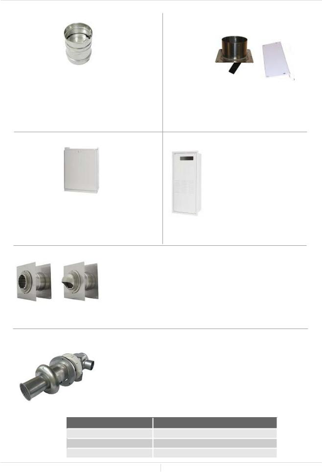
1. Backflow Preventer: 9007678005 (TK-BF01)
The Backflow preventer prevents the backflow of air through the exhaust vent. This helps prevent harmful exhaust gases from entering the home, as wellashelpingtopreventtheunitfromfreezingin areas where cold air can be blown or drawn into the exhaust system. Install this vent damper in accordance with the installation instructions and any applicable codes.
3. Pipe covers: 9007670005 (TK-PC01)
The pipe cover protects the plumbing pipes to thewaterheaterfromunexpectedadjustments. This pipe cover is fixed to the bottom of the water heater, which hides the plumbing and improves the visual aspects of the whole installation for the water heater.
2. Direct-Vent Conversion Kit: 9007667005
(TK-TV10)
This kit can be used to convert the water heater from a standard vent system to a directvent (or sealed combustion) system. Install this conversion kit in accordance with the installation instructions and any applicable codes.
4. Recess box: 9007674005 (TK-RB02)
The Recess box will allow for “clean” installations. The water heater fits inside the recess box, whichhidesandprotectsthewhole water heater and plumbing. The Recess box will fit in-between most wall studs.
5. T-Vent Wall Thimble with Termination: 9007608005 (TK-KPWL4) and 9007609005 (TK-KPWH4)
Louver Termination Hood Termination 9007608005 9007609005
(TK-KPWL4) (TK-KPWH4)
These terminations are used when venting out through the wall and are compatible with the T-Vent pipe system. These terminations are special stainless steel vents for gas appliances and are UL listed as CategoryII,IIIandIV.Therearetwotypesofterminations:theLouver terminationandtheHoodtermination.Fordifferentwallthicknesses, therearetworangesoflengthsavailable(refertotheT-Vent brochure for details). Install these vent terminations in accordance with their installation instructions and any applicable local codes.
6. Direct-Vent Concentric Termination: 900768005 (TK-KPCT43)
Used when terminating direct-vent (sealed-combustion) systems, with direct-vent models that require a 3 in. (76 mm) intake and a 4 in. (102 mm) exhaust. This concentric termination provides the convenience of only having to make one penetration through a sidewall instead of two separate penetrations for the intake and exhaust piping. The termination includes a bird screen, restricting small animals, pests, and foreign objects from entering into the vent system. This sidewall termination is available in three different sizes, to cover all ranges of wall thicknesses.
Part# |
Convering wall thicknesss |
9007680005 (TK-KPCT43-1) |
3.9 – 7.1 in. (99 - 180 mm) |
9007772005 (TK-KPCT43-2) |
6.9 – 10.1 in. (175 - 257 mm) |
9007773005 (TK-KPCT43-3) |
9.8 – 13.0 in. (249 - 330 mm) |
10 Page
WARNING FOR INSTALLATIONS
FOR YOUR SAFETY, READ BEFORE INSTALLATION:
Do not install the heater where water, debris or flammable vapors may get into the flue terminal. This may cause damageto the heaterand void the warranty.
Do not have the vent terminal pointing toward any opening into a building. Do not locate your heater in a pit or location where gas and water can accumulate.
Prohibited
Do not install this water heater under an overhang less than 3 ft. (914 mm) from its top or eaves. The area under an overhang must be open to three sides. (Outdoor models only)
Prohibited
Do not install the water heater vent terminator within1ft.(305mm)intheUSAofanyairintake or building opening, and with in 3 ft. (914 mm) in Canada of any air intake or building opening. (Outdoor models only) (Refer to p.15)
3 ft.
(914 mm)
Do not install next to a dryer or any source of airborne debris that can be trapped inside the combustion chamber, unless the system is direct vented.
1ft.(305mm)USA
3ft.(914mm)Canada
1ft.(305mm)USA |
1ft.(305mm)USA |
3ft.(914mm)Canada |
3ft.(914mm)Canada |
11 Page

Installation Manual
Installation
HIGH-ALTITUDE INSTALLATIONS
Check the elevation where your water heater is installed. Set DIPswitches shown in the table below depending on the altitude.
Indoor models
Altitude |
0 (DEFAULT) |
Up to 2,500 ft |
Up to 5,000 ft |
Up to 7,500 ft |
Over 7,500 ft |
||||||
DIPswitches |
|||||||||||
|
|
|
|
|
|
|
|
|
|
||
|
O N 1 2 3 4 5 6 7 8 |
O N 1 2 3 4 5 6 7 8 |
O N 1 2 3 4 5 6 7 8 |
O N 1 2 3 4 5 6 7 8 |
|
||||||
110U (T-KJr2U) and |
O F |
F |
O |
F |
F |
O F |
F |
O F |
F |
|
|
310 (T-K4U) models |
|
No. 3 : OFF |
|
|
No. 3 : OFF |
|
No. 3 : OFF |
|
No. 3 : OFF |
Consult our |
|
|
|
|
|
|
|
||||||
|
|
No. 4 : OFF |
|
|
No. 4 : ON |
|
No. 4 : OFF |
|
No. 4 : ON |
Technical |
|
|
|
No. 5 : OFF |
|
|
No. 5 : OFF |
|
No. 5 : ON |
|
No. 5 : ON |
||
|
|
|
|
|
|
Services |
|||||
|
O N 1 2 3 4 5 |
O N 1 2 3 4 5 |
O N 1 2 3 4 5 |
O N 1 2 3 4 5 |
|||||||
|
at 1-888- |
||||||||||
510U (T-D2U) models |
|
|
|
|
|
|
|
|
|
||
O |
F F |
O |
|
F F |
O |
F F |
O |
F F |
479-8324 |
||
(Lower bank of |
|
No. 2 : OFF |
|
|
No. 2 : OFF |
|
No. 2 : OFF |
|
No. 2 : OFF |
|
|
DIPswitches) |
|
|
|
|
|
|
|||||
|
No. 3 : OFF |
|
|
No. 3 : ON |
|
No. 3 : OFF |
|
No. 3 : ON |
|
||
|
|
|
|
|
|
|
|||||
|
|
No. 4 : OFF |
|
|
No. 4 : OFF |
|
No. 4 : ON |
|
No. 4 : ON |
|
|
Outdoor models
Altitude |
0 (DEFAULT) |
Up to 2,000 ft |
Up to 4,000 ft |
Up to 6,000 ft |
Over 6,000 ft |
||||||
DIPswitches |
|||||||||||
|
|
|
|
|
|
|
|
|
|
||
|
O N 1 2 3 4 5 6 7 8 |
O N 1 2 3 4 5 6 7 8 |
O N 1 2 3 4 5 6 7 8 |
O N 1 2 3 4 5 6 7 8 |
|
||||||
110U (T-KJr2U) and |
O F |
F |
O |
F |
F |
O F |
F |
O F |
F |
|
|
310 (T-K4U) models |
|
No. 3 : OFF |
|
|
No. 3 : OFF |
|
No. 3 : OFF |
|
No. 3 : ON |
Consult our |
|
|
|
|
|
|
|
||||||
|
|
No. 4 : OFF |
|
|
No. 4 : ON |
|
No. 4 : OFF |
|
No. 4 : OFF |
Technical |
|
|
|
No. 5 : OFF |
|
|
No. 5 : OFF |
|
No. 5 : ON |
|
No. 5 : ON |
||
|
|
|
|
|
|
Services |
|||||
|
O N 1 2 3 4 5 |
O N 1 2 3 4 5 |
O N 1 2 3 4 5 |
O N 1 2 3 4 5 |
|||||||
|
at 1-888- |
||||||||||
510U (T-D2U) models |
|
|
|
|
|
|
|
|
|
||
O |
F F |
O |
|
F F |
O |
F F |
O |
F F |
479-8324 |
||
(Lower bank of |
|
No. 2 : OFF |
|
|
No. 2 : OFF |
|
No. 2 : OFF |
|
No. 2 : ON |
|
|
DIPswitches) |
|
|
|
|
|
|
|||||
|
No. 3 : OFF |
|
|
No. 3 : ON |
|
No. 3 : OFF |
|
No. 3 : OFF |
|
||
|
|
|
|
|
|
|
|||||
|
|
No. 4 : OFF |
|
|
No. 4 : OFF |
|
No. 4 : ON |
|
No. 4 : ON |
|
|
NOTE: ThedarksquaresindicatethedirectiontheDIPswitchesshouldbesetto.
110U (T-KJr2U) and 310U (T-K4U) models |
510U (T-D2U) models |
Computer board |
Computer board |
DIPswitches |
DIPswitches (Lower bank) |
|
DO NOT adjust any DIPswitches on the upper bank for the 510U (T-D2U) WARNING models.
12 Page
Installation Manual
Installation
VENTING INSTRUCTIONS
For indoor models
-General-
• Improper venting of this appliance can result in excessive levels of carbon monoxide which can result in severe personal injury or death.
 • Improper installation can cause nausea or asphyxiation, severe injury or death DANGER fromcarbonmonoxideandfluegasespoisoning.Improperinstallationwillvoid
product warranty.
|
|
When installing the vent system, all applicable national and local codes must be |
|
|
followed. If you install thimbles, fire stops or other protective devices and they |
|
CAUTION |
penetrate any combustible or noncombustible construction, be sure to follow all |
|
applicable national and local codes. |
The water heater must be vented in accordance with the section “Venting of Equipment" of the latest edition of the National Fuel Gas Code: ANSI Z223.1/NFPA 54 in the United States and/or Section 7 of the CAN/CSA B149.1 Natural Gas Installation Code in Canada, as well as applicable local building codes.
The manufacturer recommends the “T-Vent” line manufactured by TAKAGI (Refer to “T-Vent” brochure for details). However, the following are also UL listed manufacturers: ProTech Systems Inc. (FasNSeal), Flex-L Inc., Z-Flex Inc. (Z-Vent III), Metal-Fab Inc., and Heat-Fab Inc. (Saf-T Vent).
General rules for venting water heaters are:
•Place the water heater as close as possible to the vent terminator.
•The vent collar of the water heater must be fastened directly to an unobstructed vent pipe.
•Do not weld the vent pipe to the water heater’s vent collar.
•Do not cut the vent collar of the unit.
•The vent must be easily removable from the top of the water heater for normal service and inspection of the unit.
•The water heater vent must not be connected to any other gas appliance or vent stack.
•Avoid using an oversized vent pipe or using extremely long runs of the pipe.
•For rooftop venting, a rain cap or other form of termination that prevents rain water from entering into the water heater must be installed.
•Do not common vent or connect any vent from other appliances to the water heater vent.
General rules for vent terminations:
•Avoid locating the water heater vent terminator near any air intake devices. These fans can pick up the exhaust flue products from the water heater and return them to the building. This can create a health hazard.
•Locate the vent terminator so that it cannot be blocked by any debris, at any time. Most codes require that the terminator must be at least 12 in. (305 mm) above grade, but the installer may determine if it should be higher depending on the job site condition and applicable codes.
•A proper sidewall terminator is recommended when the water heater is vented through a sidewall.
•Regarding the clearances from the exhaust terminator to the air inlet or opening, refer to the next few pages.
13 Page

Installation Manual
Installation
-Vent length and No. of Elbow-
This is a Category III appliance and must be vented accordingly. The vent system must be sealed air tight. All seams and joints without gaskets must be sealed with high heat resistant silicone sealant or UL listed aluminum adhesive tape having a minimum temperature rating of 350 °F (177 °C). For best results, a vent system should be as short and straight as possible.
•This water heater is a Category III appliance and must be vented accordingly with any 4 in. (102 mm) vent approved for use with Category III or Special BH type gas vent.
•Follow the vent pipe manufacturer’s instructions when installing the vent pipe.
•Do not common vent this appliance with any other vented appliance (Do not terminate vent into a chimney. If the vent must go through the chimney, the vent must run all the way through the chimney with Category III approved or Special BH vent pipe).
•When the horizontal vent run exceeds 5 ft. (1.5 m), support the vent run at 3 ft. (0.9 m) intervals with overhead hangers.
•The maximum length of exhaust vent piping must not exceed 50 ft. (15.2 m) (deducting 5 ft. (1.5m) for each elbow used in the venting system). Do not use more than 5 elbows.
Diameter |
Max. No. of Elbow Max. Vertical and Horizontal (Total) Vent Length |
|
4 in. (102 mm) |
5 |
50 ft. (15.2 m ) |
*For each elbow added, deduct 1.5m (5 ft.) from max. vent length. |
||
No. of Elbows |
Max. Vertical or Horizontal Vent Length |
|
0 |
|
50 ft. (15.2 m) |
1 |
|
45 ft. (13.7 m) |
2 |
|
40 ft. (12.2 m) |
5 |
|
25 ft. (7.6 m) |
Excludes elbow termination, rain caps, or the 4 in. (102 mm) PVC Concentric Termination
-DIPswitch settings for Direct Vent models-
Set DIPswitches shown in the table below depending on the vent length.
110U Direct vent (T-KJr2U-IN) |
510U Direct vent (T-D2U-IN) |
Vent length |
|||||||
310 Direct vent (T-K4U-IN) |
(Upper bank of DIPswitches) |
||||||||
|
|||||||||
O |
N 1 |
2 3 4 5 6 |
971 |
80 |
O |
N 1 2 3 4 |
57 6 8 |
|
|
O |
F F |
|
|
|
O |
F F |
|
0 to 30 ft |
|
|
|
No. 6 : ON |
|
|
|
No. 3 : ON |
|
||
|
|
|
|
|
|
|
|||
|
|
No. 7 : OFF |
|
|
|
No. 4 : OFF |
|
||
O |
N 1 |
2 3 4 5 6 |
971 |
80 |
O |
N 1 2 3 4 |
57 6 8 |
|
|
O |
F F |
No. 6 : ON |
|
|
O |
F F |
|
31 to 50 ft |
|
|
|
|
|
|
No. 3 : ON |
|
|
||
|
|
No. 7 : ON |
|
|
|
No. 4 : ON |
|
|
|
14 Page
Installation Manual
Installation
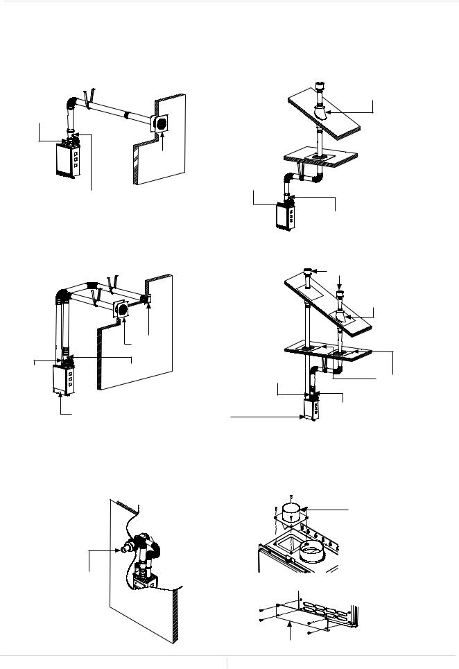
-Venting Illustrations-
For the 110U Indoor (T-KJr2U-IN), 310U Indoor (T-K4U-IN) and 510U Indoor (T-D2U-IN) models
For details of the optional items, refer to the Installation manual for each Optional item.
Horizontal Installation Diagram |
Vertical Installation Diagram |
|
|
|
Rain Cap |
Wall |
|
Roof Flashing |
|
Roof |
|
|
|
|
Backflow
Preventer*
 SidewallVent
 Terminator
Backflow
Preventer*
Vertical Condensation Drain**
Vertical Condensation Drain** |
Horizontal Installation Diagram |
Vertical Installation Diagram |
||
(With direct-venting) |
(With direct-venting) |
||
|
Wall |
|
Rain Cap |
|
|
Roof |
|
|
|
|
Roof |
|
|
|
Flashing |
|
Sidewall Vent |
|
|
|
Terminator |
|
|
Backflow |
Vertical Condensation |
Backflow |
|
Preventer* |
Drain** |
Preventer* |
Fire stop |
|
See the picture below for detailed connection |
|
Vertical Condensation Drain** |
|
|
|
|
|
instructions to Direct-Vent Conversion Kit. |
|
|
*Backflow Preventer (Recommended for freezing weather conditions: 36 °F (2 °C) and below). **Vertical Condensation Drain must be installed in accordance with local codes.
Horizontal Installation Diagram With
Direct-Vent Concentric Termination
Wall 


Direct-vent
Concentric
Termination
Installation Diagram of Direct-Vent
Conversion Kit with water heater
IntakeportofDirect-Vent
Conversion Kit
(For details see P.10)
The water heater
Plate of Direct-Vent Conversion Kit
15 Page
Installation Manual
Installation
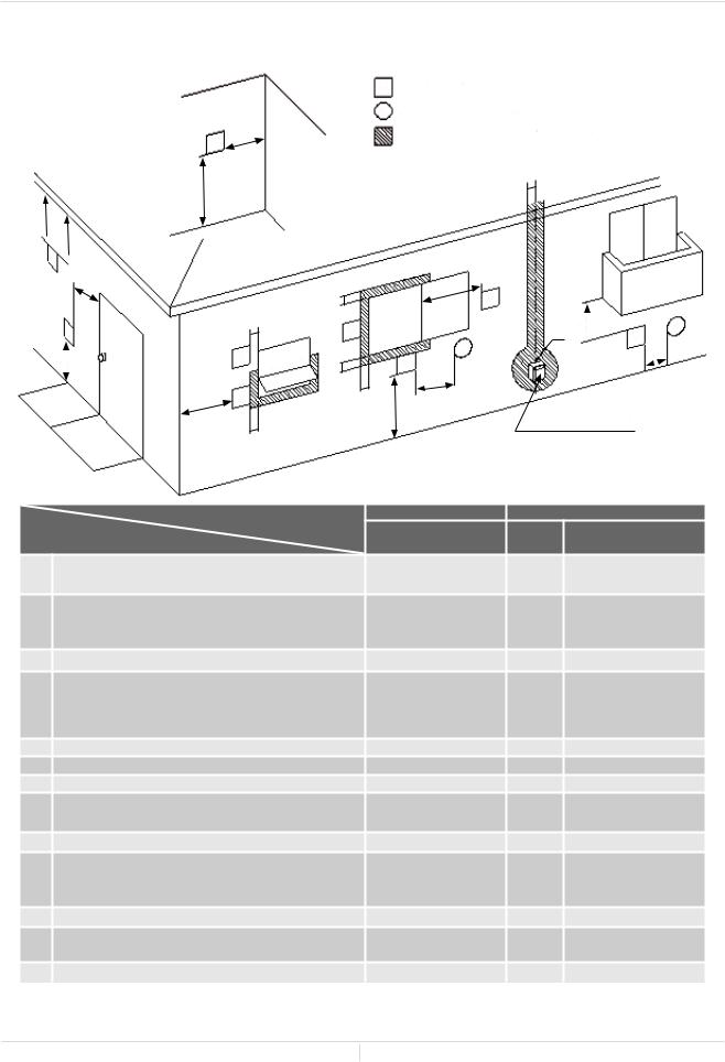
-Vent termination clearances-
D
 E V
E V 
B
V
L
INSIDE CORNER DETAIL |
|
V |
Vent terminal |
X |
Air supply inlet |
V G |
Area where is not permitted |
|
H |
A
C
|
V |
FIXED |
|
|
CLOSED |
F |
V |
OPERABLE |
|
B
B
V
B
|
B |
V |
|
FIXED |
|
OPERABLE |
|
|
CLOSED |
|
X
V
J
BA
I M V X
V X  K
K
Gas meter / regulator
|
|
Canada |
|
U.S.A |
|
|
Direct vent and other |
Direct |
Other than |
|
|
than Direct Vent |
vent |
Direct Vent |
A |
Clearance above grade, veranda, porch, deck, or |
1 foot |
1 foot |
1 foot |
balcony. |
||||
|
|
|
|
4 feet from below or |
B |
Clearance to window or door that may be opened |
3 feet |
1 foot |
side opening. 1 foot |
|
|
|
|
from above opening. |
C |
Clearance to permanently closed window |
* |
* |
* |
|
Vertical clearance to ventilated soffit located above |
|
|
|
D |
the vent terminator within a horizontal distance |
* |
* |
* |
of 2 feet (61cm) from the center line of the |
||||
|
terminator. |
|
|
|
E |
Clearance to unventilated soffit |
* |
* |
* |
F |
Clearance to outside corner |
* |
* |
* |
G |
Clearance to inside corner |
* |
* |
* |
H |
Clearance to each side of center line extended |
3 feet |
* |
* |
above meter/regulator assembly |
||||
I |
Clearance to service regulator vent outlet. |
3 feet |
* |
* |
|
Clearance to non-mechanical air supply inlet to |
|
|
4 feet from below or |
J |
building or the combustion air inlet to any other |
3 feet |
1 foot |
side opening. 1 foot |
|
application |
|
|
from above opening. |
K |
Clearance to mechanical air supply inlet. |
6 feet |
3 feet |
3 feet |
L |
Clearance above paved sidewalk or paved driveway |
7 feet |
* |
7 feet |
located on public property. |
||||
M |
Clearance under veranda, porch deck, or balcony. |
1 foot |
* |
* |
*For clearances not specified in ANSI Z223.1 / NFPA 54 or CAN/CSA-B149.1, please use clearances in accordance with local installation codes and the requirements of the gas supplier.
16 Page

Installation Manual
Installation
-For sidewall terminations-
1 ft. |
2 ft. |
(610 mm) |
|
(305 mm) |
|
1 ft. |
|
(305 mm) |
|
Exhaust |
Inside |
termination |
corner |
1 ft. |
2 ft. |
(610 mm) |
|
(305 mm) |
|
1 ft. |
|
(305 mm) |
|
Combined |
|
intake and |
Inside |
exhaust |
|
termination |
corner |
For multiple sidewall exhaust terminations (e.g. multiunit systems), an exhaust termination must be at least 1 ft. (305mm) away from another exhaust termination. An exhaust termination must also be at least 2 ft. (610 mm) awayfromaninsidecorner(iftheadjacentwallislessthan 2 ft. (610 mm) of length, the minimum required distance away from the inside corner will be equal to the length of that adjacent wall).
For multiple-unit, direct-vent sidewall terminations that combine the intake and exhaust into a single penetration, space each direct-vent termination at least 1 ft. (305 mm) awayfromeachother,nomattertheorientation. Adirectventterminationmustalsobeatleast2ft.(610mm)away from an inside corner (if the adjacent wall is less than 2 ft. (610 mm) of length, the minimum required distance away from the inside corner will be equal to the length of that adjacent wall).
Exhaust termination
 3 ft.
3 ft.
(915 mm)


 3 ft.
3 ft.
 3 ft.
3 ft. 
 (915 mm)
 (915
(915  mm)
mm)
 Air supply inlet
For direct-vent sidewall terminationsthatusetwo separatepenetrationsfor the intake and exhaust, distance the intake and exhaust terminations at least3ft.(915mm)away from each other, no matter the orientation.
Exhaust |
and/or |
|
|
direct-vent |
sidewall |
|
|
terminations should |
|
||
be at least 2 ft. (610 |
2 ft. |
||
mm) away from an |
|||
opposite |
surface/ |
(610 mm) |
|
wall.Donotplacethe |
Exhaust |
||
termination |
directly |
||
termination |
|||
infrontofanopening |
|
||
into a building. |
|
||
A-For rooftop terminations-
A |
2ft. |
A |
(610 mm) |
A


 A
A


 Air intake
Exhaust termination
A: In accordance with local codes
Exhaust 


 termination


Air intake


For multiple-unit rooftop terminations (whether for standard or direct-vent installations) space all exhaust and intake terminations in accordance with local codes. An exhaust termination must be spaced from a wall or surface in accordance with local codes as well. In the absence of such a code, an exhaust termination must be a horizontal distance of at least 2 ft. (610 mm) away from a wall or surface.
Please follow all local and national codes in regards to proper termination clearances. In the absence of such codes, the following clearances can be used as
CAUTION guidelines. Local codes supersede these guidelines.
17 Page
 Loading...