


BTH-300

MODELS COVERED:
BTH 120 thru 500 Models
SERIES 100, 101 and BTH 500 Series104
500 Tennessee Waltz Parkway
Ashland City, TN 37015
PRINTED IN THE U.S.A. 1010 316586-001
SERVICING SHOULD ONLY BE PERFORMED BY A QUALIFIED SERVICE AGENT
Service Handbook
COMMERCIAL GAS HIGH EFFICIENCY WATER HEATERS


1
Servicing should only be performed by a Qualied Service Agent
TABLE OF CONTENTS
INTRODUCTION ......................................................................2
QUALIFICATIONS .....................................................................2
TOOLS REQUIRED ....................................................................3
GENERAL INFORMATION...............................................................4
GAS PRESSURE SPECIFICATIONS ......................................................4
INSTALLATION QUICK TIPS – BTH 120 AND 150 GAS PRESSURE .............................5
INSTALLATION QUICK TIPS – BTH 199 AND 250 GAS PRESSURE .............................7
INSTALLATION QUICK TIPS – BTH 300, 400, 500 GAS PRESSURE . . . . . . . . . . . . . . . . . . . . . . . . . . . . . 8
INSTALLATION QUICK TIPS – BTH 300, 400, 500 ............................................9
INSTALLATION – VENTING CATEGORY AND MATERIALS ...................................10
VENTING TABLES – BTH 120 - 250 ......................................................11
VENTING TABLES – BTH 300, 400, 500...................................................11
CONCENTRIC VENTING...............................................................12
VENT CONDENSATION ...............................................................13
VENTING – ALL MODELS – SINGLE PIPE POWER VENT – USING ROOM AIR ...................14
VENTING – ALL MODELS – TWO PIPE DIRECT VENT – USING OUTSIDE AIR ...................15
VENT TERMINATION – DIRECT VENT – ALL MODELS ......................................16
DIRECT VENTING – ALL MODELS.......................................................17
CONTROL OVERVIEW ................................................................18
ADJUSTING TANK TEMPERATURE – OPERATING SET POINT – DIFFERENTIAL.................20
CHANGING THE DISPLAY UNITS .......................................................22
FAULT AND WARNING CONDITIONS – ADVANCED DIAGNOSTIC INFORMATION ................24
ACCESS TO THE CURRENT FAULT OR WARNING .........................................25
FAULT CODES.......................................................................26
VIEWING THE FAULT HISTORY – VIEWING INFORMATION ABOUT THE HEATER................27
CONTROL SEQUENCE (TYPICAL ALL MODELS) ...........................................28
CONTROL SEQUENCE FLOW CHART ...................................................29
CONTROLS – CENTRAL CONTROL BOARD – CCB .........................................30
CONTROLS – GAS VALVE BTH 120......................................................32
CONTROLS – GAS VALVE BTH 150......................................................32
CONTROLS – GAS VALVE BTH 199 AND 250 ..............................................33
CONTROLS – GAS VALVE BTH 199 AND 250 ..............................................34
CONTROLS – GAS VALVE, ORIFICE CHART – BTH 300/400..................................35
CONTROLS – GAS VALVE, ORIFICE CHART – BTH 500 .....................................36
CONTROLS – PRESSURE SWITCHES – ALL MODELS ......................................37
CONTROLS – PRESSURE SWITCHES – BTH 120 THROUGH 250 .............................38
CONTROLS – PRESSURE SWITCHES – BTH 300, 400, 500 . . . . . . . . . . . . . . . . . . . . . . . . . . . . . . . . . . 39
CONTROLS – CONNECTIONS, IGNITER, FLAME SENSOR, SIGHT GLASS, POWERED ANODES ...40
HOT SURFACE IGNITER / FLAME SENSOR / CONTROL TIMING ..............................41
BLOWER SPEED CONTROL BTH 199 AND 250 ............................................42
VARIABLE FREQUENCY DRIVE – BTH 400 AND 500........................................43
VARIABLE FREQUENCY DRIVE – BLOWER SPEED AND PRESSURE READINGS................44
WIRING DIAGRAM – BTH 120 - 300......................................................45
WIRING DIAGRAM – BTH 400, 500 ......................................................46

2
Servicing should only be performed by a Qualied Service Agent
INTRODUCTION
The service handbook is designed to aid in servicing and troubleshooting A.O. Smith Cyclone Xi BTH
commercial water heaters in the field. No duplication or reproduction of this book may be made without the
express written authorization of the A.O. Smith Water Products Company.
The following text and illustrations will provide you with a step by step procedure to verify proper
installation, operation, and troubleshooting procedures. Additional quick reference data is included to assist
you in servicing these products.
The information contained in this handbook is designed to answer commonly faced situations encountered
in the operation of this product line and is not meant to be all inclusive. If you are experiencing a problem
not covered in this handbook, please contact A.O. Smith Technical Information at 1-800-527-1953, by
email at help@hotwater.com, or your local A.O. Smith Water Products Company representative for
further assistance. Our website at: http://www.hotwater.com is also a resource for installation and service
information. This handbook is intended for use by licensed plumbing professionals and reference should
be made to the installation manual accompanying the product. This handbook contains supplemental
information to the product’s installation and operation manual.
QUALIFICATIONS
ANSI Z223.1 Sec 3.3.83
“Qualified Agency”
“Any individual, firm, corporation or company that either in person or through a representative is engaged
in and is responsible for (a) the installation, testing or replacement of gas piping or (b) the connection,
installation, testing, repair or servicing of appliances and equipment; that is experienced in such work; that
is familiar with all precautions required; and that has complied with all the requirements of the authority
having jurisdiction.”
Service of this water heater requires ability equivalent to that of a Qualified Service Agent (licensed
tradesman) in the field involved. Installation skills such as plumbing, air supply, venting, gas supply,
electrical supply are required in addition to electrical testing skills. Some products may require combustion
testing equipment and certification. If you do not possess these skills or do not have the proper tools you
should not attempt to service this water heater.
3
Servicing should only be performed by a Qualied Service Agent
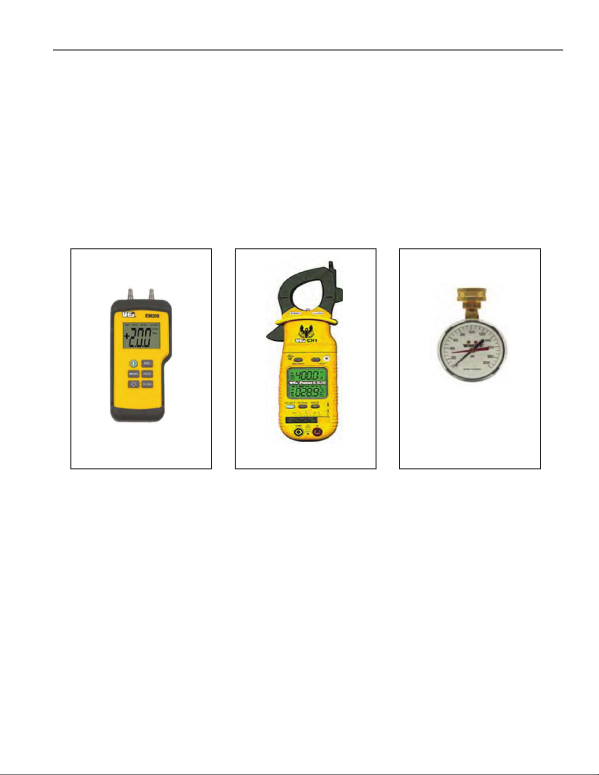
TOOLS REQUIRED
• ELECTRICAL MULTIMETER CAPABLE OF MEASURING CONTINUITY/ OHMS, AC & DC VOLTS,
AMPERES, MICROAMPERES, MILLIVOLTS, and FREQUENCY (Hz)
• UEi Model DL289 or equivalent
• DIGITAL MANOMETER + 60" W. C. in .01" increments
Note: A digital manometer is required for testing pressure switches and can replace a gas pressure
gauge, draft gauge or slack tube manometer for checking gas pressure.
• UEi model EM200 or equivalent
• WATER PRESSURE GAUGE w/LAZY HAND AND HOSE BIBB CONNECTION
• THERMOMETER
• 1-1/16 INCH SOCKET WITH EXTENSION FOR ANODE REPLACEMENT
• SET OF NUMBERED DRILL BITS
DIGITAL MANOMETER DIGITAL MULTIMETER
WATER PRESSURE
TEST GAUGE W/LAZY
HAND AND HOSE BIBB
CONNECTION

4
Servicing should only be performed by a Qualied Service Agent
GENERAL INFORMATION
INSTALLATION REQUIREMENTS FOR THE COMMONWEALTH OF MASSACHUSETTS
For all side wall terminated, horizontally vented power vent, direct vent, and power direct vent gas fueled
water heaters installed in every dwelling, building or structure used in whole or in part for residential
purposes, including those owned or operated by the Commonwealth and where the side wall exhaust vent
termination is less than seven (7) feet above finished grade in the area of the venting, including but not
limited to decks and porches, the following requirements shall be satisfied:
INSTALLATION OF CARBON MONOXIDE DETECTORS
At the time of installation of the side wall horizontal vented gas fueled equipment, the installing plumber
or gas fitter shall observe that a hard wired carbon monoxide detector with an alarm and battery back up
is installed on the floor level where the gas equipment is to be installed. In addition, the installing plumber
or gas fitter shall observe that a battery operated or hard wired carbon monoxide detector with an alarm
is installed on each additional level of the dwelling, building or structure served by the sidewall horizontal
vented gas fueled equipment. It shall be the responsibility of the property owner to secure the services of
qualified licensed professionals for the installation of hard wired carbon monoxide detectors. In the event
that the side wall horizontally vented gas fueled equipment is installed in a crawl space or an attic, the hard
wired carbon monoxide detector with alarm and battery back-up may be installed on the next adjacent
floor level. In the event that the requirements of this subdivision can not be met at the time of completion
of installation, the owner shall have a period of thirty (30) days to comply with the above requirements
provided that during said thirty (30) day period, a battery operated carbon monoxide detector with an alarm
shall be installed.
APPROVED CARBON MONOXIDE DETECTORS
Each carbon monoxide detector as required in accordance with the above provisions shall comply with
NFPA 720 and be ANSI/UL 2034 listed and CSA certified.
SIGNAGE
A metal or plastic identification plate shall be permanently mounted to the exterior of the building at
a minimum height of eight (8) feet above grade directly in line with the exhaust vent terminal for the
horizontally vented gas fueled heating appliance or equipment. The sign shall read, in print size no less
than one-half (1/2") inch in size,
“GAS VENT DIRECTLY BELOW. KEEP CLEAR OF ALL OBSTRUCTIONS.”
GAS PRESSURE SPECIFICATIONS
MODELS
Natural
120-150
Propane
120-150
Natural
199-250
Propane
199-250
Natural
300/400/500
Propane
300/400/500
Maximum Gas
Supply Pressure
10.5" WC
(2.59 kPa)
14.0" WC
(3.45 kPa)
10.5" WC
(2.59 kPa)
14.0" WC
(3.45 kPa)
11.0" WC
(2.74 kPa)
14.00" WC
(3.49 kPa)
Nominal Gas
Supply Pressure
7.0" WC
(1.74 kPa)
11.0" WC
(2.74 kPa)
7.0" WC
(1.74 kPa)
11.0" WC
(2.74 kPa)
7.0" WC
(1.74 kPa)
11.0" WC
(2.74 kPa)
Minimum Gas
Supply Pressure
(Low Gas Press.
Switch Setting)
4.8" WC
(1.20 kPa)
11.0" WC
(2.74 kPa)
4.8" WC
(1.20 kPa)
8.5" WC
(2.12 kPa)
5.2" WC
(1.54 kPa)
11.0" WC
(2.74 kPa)
Manifold Pressure
4.0" WC
(0.98 kPa)
10.0" WC
(2.49 kPa)
0" WC
(0 kPa)
0" WC
(0 kPa)
4.00" WC
(1.25 kPa)
10.0" WC
(2.49 kPa)

5
Servicing should only be performed by a Qualied Service Agent
INSTALLATION QUICK TIPS – BTH 120 AND 150 GAS PRESSURE
ADJUSTMENT PROCEDURE: GAS PRESSURE BTH 120 AND 150 MODELS
Main line gas pressure to the water heater for natural gas should be between a maximum of 10.5" w.c.
(2.59 kPa) for natural gas, 14.0" w.c. (3.45 kPa) for propane and a minimum of 4.8 w.c. (1.18 kPa) for
Natural Gas, and 8.5" w.c. (2.08 kPa) for Propane Gas. Also see gas pressure specification table on
page 4.
A supply gas pressure regulator (service regulator) must be installed on the gas supply line within
10' (305 cm) of the unit.
1. Check gas line pressure with a manometer.
2. Check manifold pressure gauge (manometer) connected to the manifold pressure tap on the gas
control valve. If full rate adjustment is required, remove cover screw from top of the gas control
valve. Using a small screwdriver, turn adjusting screw clockwise to increase or counterclockwise to
decrease gas pressure to obtain 4.0" w.c. (1 kPa) for natural gas and 10.0" w.c. (2.5 kPa) for L.P.
Gas.
3. Cycle the burner on and off several times to check its operation.
4. Check the operation of the limit and operating controls.
5. Check the vent system seams and joints and ensure that there is no discharge of flue products into
the room.
6. Check the input rate.
HIGH ALTITUDE INSTALLATIONS BTH 120 - 150
For appliance installation locations with elevations above 6,500 feet (1982 meters) consult the “High
Altitude Installation” section of the owners manual.
1. Attach a pressure gauge (manometer) to the manifold pressure tap and refer to page 4 for correct
pressure.
2. Use this formula to “clock” the meter. Be sure other gas consuming appliances are not operating
during this interval.
Btuh = 3600 X H/ T
T = Time in seconds to burn 1 cubic foot of gas.
(With a stopwatch read the gas meter and measure the amount of time required for the heater to
consume 1 cubic foot of gas.)
H = Heating value of gas (in Btu’s per cubic foot of gas).
Btuh = Actual heater input rate, in Btuh.
EXAMPLE: (Using BTH-150 heater)
T = 25.25 seconds
H = 1050 Btu/ft.
3
BTUH = ?

6
Servicing should only be performed by a Qualied Service Agent
Compare result to the de-rated input required for the elevation at the installation location.
Should it be necessary to adjust the gas pressure to the burner, to obtain the full input rate, the steps below
should be followed:
3. Remove the pressure regulator cover screw and adjust the pressure by turning the adjusting screw
with a small screwdriver. Do not exceed 4.0" (1 kPa) natural gas models and 10.0" w.c. (2.5 kPa)
on the propane models. Clockwise to increase gas pressure and input rate. Counterclockwise to
decrease gas pressure and input rate.
4. “Clock” the meter as in step (2) above.
5. Repeat steps (3) and (4) until the specified input rate is achieved.
6. Turn the manual gas valve to “OFF”. Replace the pressure regulator cover screw. Remove the
pressure gauge or manometer from the manifold pressure tap. Replace the set screw in the
manifold pressure tap. If the gas pressure regulator cannot be adjusted to give the full input rating
with sufficient gas pressure at the valve, check to ensure the unit is equipped with the correct
orifice.
7
Servicing should only be performed by a Qualied Service Agent
INSTALLATION QUICK TIPS – BTH 199 AND 250 GAS PRESSURE
ADJUSTMENT PROCEDURE: GAS PRESSURE BTH 199 AND 250 MODELS
IMPORTANT NOTE
THE BTH 199 AND 250 MODELS INCORPORATE A NEW GAS CONTROL, WHICH OPERATES AT
A MANIFOLD PRESSURE OF 0" w.c. (0 kPa) FOR BOTH NATURAL AND PROPANE GAS. SEE
THE GAS PRESSURE CHART ON PAGE 4. THESE MODELS ARE CONFIGURED PRIOR TO BEING
SHIPPED FROM THE FACTORY AND NO ADJUSTMENTS ARE NECESSARY PRIOR TO STARTUP.
THE CONTROLLER MONITORS THE AIR FLOW AND MAKES ADJUSTMENTS TO THE FAN SPEED
WHICH IN EFFECT CONTROLS THE AMOUNT OF GAS FLOW. THEREFORE, THE UNIT WILL SELF
ADJUST TO ACQUIRE THE CORRECT AMOUNT OF INPUT.
“Supply gas pressure to the water heater must not exceed a maximum of 10.5" w.c. (2.95 kPa) for natural
gas, or 14" w.c. (3.45 kPa) for propane. The minimum supply gas pressure is 4.8" w.c. (1.20 kPa) for
natural gas and 8.5" w.c. (2.12 kPa) for propane gas.”
Once the unit is installed and filled with water and the inlet pressures confirmed, simply turn the switch on
and observe operation. Cycle the unit off and on several times to ensure proper operation.
HIGH ALTITUDE INSTALLATION
The BTH 199 and 250 models are suitable for installation up to 10,100 feet above sea level with no
adjustments.
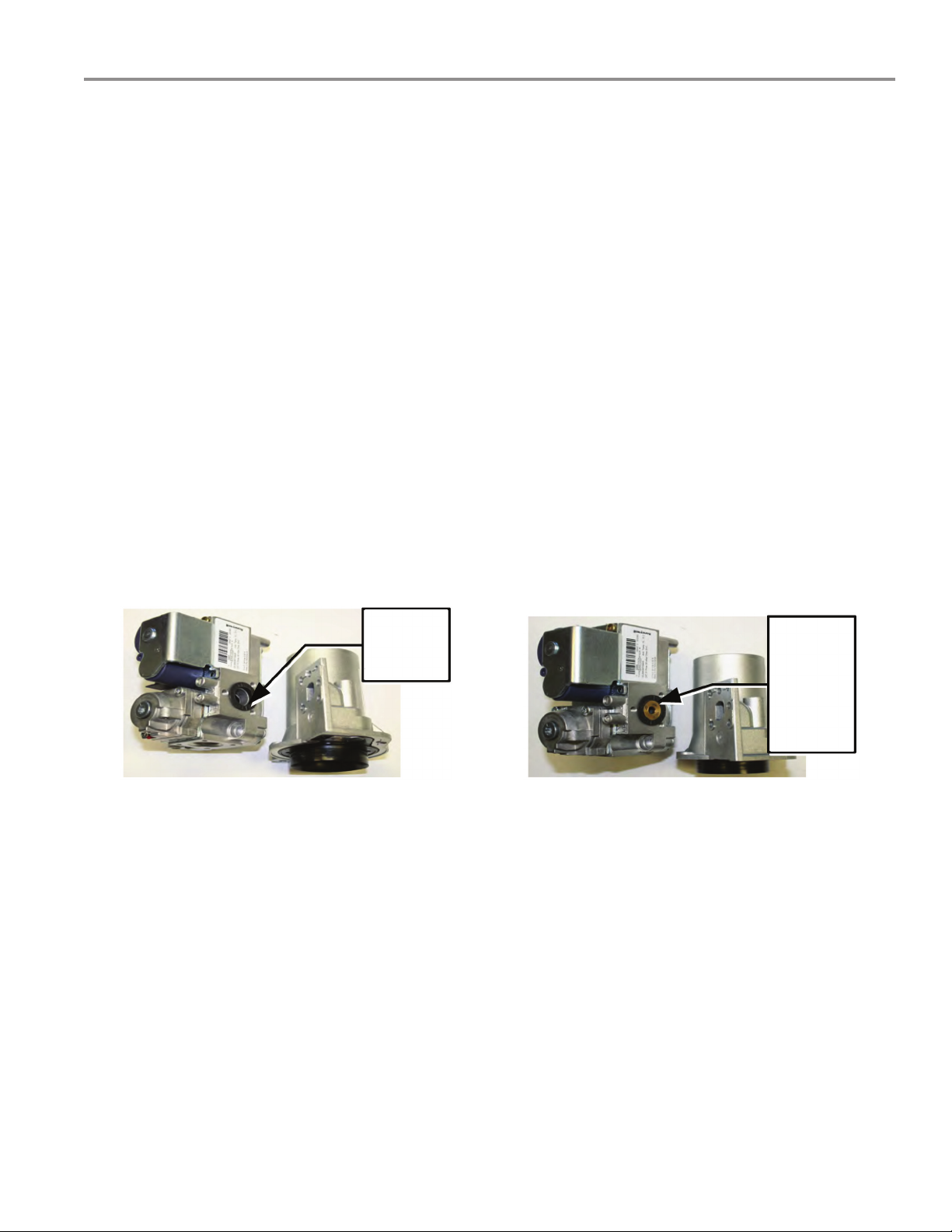
GAS ORIFICE
The BTH 199 and 250 models do not have a natural gas orifice. A .230" orifice is used on LP gas models.
Venturi
Gasket
w/o Orifice
Gas Control Without Orifice Natural Gas
Venturi
Gasket
w/LP Gas
Orifice
(.230")
Brass
Gas Control with .230" LP Orifice
A supply gas pressure regulator (service regulator) must be installed on the gas supply line within
10' (305 cm) of the unit.

8
Servicing should only be performed by a Qualied Service Agent
INSTALLATION QUICK TIPS – BTH 300, 400, 500 GAS PRESSURE
ADJUSTMENT PROCEDURE: GAS PRESSURE BTH 300, 400, 500
A minimum dynamic gas supply pressure of 5.2" w.c. (1.29 kPa) for Natural Gas and 11" w.c.
(2.74 kPa) for LP Gas is required before making any adjustment to the gas control pressure
regulator. Attempts to adjust the regulator during periods of low gas supply pressure could result in over
firing of the water heater when the gas supply pressure returns to normal.
Check gas line pressure with a manometer, adjust the gas supply line pressure Gas Pressure table on
page 4.
1. Check manifold pressure using a pressure gauge (manometer) connected to the manifold pressure
tap on the gas control valve. If full rate adjustment is required, remove cover screw from top of the
gas control valve. Using a small screwdriver, turn adjusting screw clockwise to increase or counter
clockwise to decrease gas pressure to obtain 4.0" w.c. (0.996 kPa) for Natural Gas and 10" w.c.
(2.49 kPa) for LP gas.
2. Cycle the burner on and off several times to check its operation.
3. Check the operation of the limit and operating controls.
4. Check the vent system seams and joints and ensure that there is no discharge of flue products into
the room.
5. Check the input rate as shown on page 6.
HIGH ALTITUDE ADJUSTMENT BTH 300, 400, 500
For high altitude adjustments, contact the help line on the front of the water heater or contact
help@hotwater.com.
9
Servicing should only be performed by a Qualied Service Agent
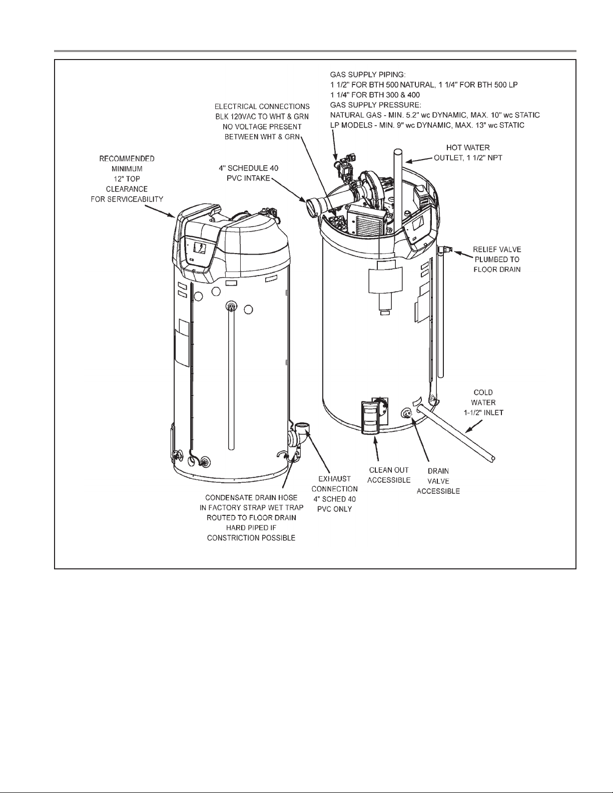
INSTALLATION QUICK TIPS – BTH 300, 400, 500
SEE MANUAL FOR COMPLETE INSTALLATION INSTRUCTIONS & DETAILS

10
Servicing should only be performed by a Qualied Service Agent
INSTALLATION – VENTING CATEGORY AND MATERIALS
CYCLONE VENTING
Category IV • Positive pressure in vent, above atmospheric.
• These models will produce excessive condensate in vent.
• Vent system must not be combined with any other appliances.
• Flue gas temperatures less than 140°F.
• Condensing water heater, thermal efficiency of this product will produce condensate in
the vent system, the heater is equipped with provision for draining condensate from vent
system.
• PH of condensate approximately 3.59; within tolerance for cast iron drains.
Type venting • May be installed Direct Vent; draws all fresh air for combustion from and discharges flue
gases to the outdoor atmosphere through 2 pipes.
• May be installed Conventional Vent; uses room air for combustion and discharges flue
gases to the outdoor atmosphere through 1 pipe.
Vertical and horizontal Vent system can be terminated vertically or horizontally (side wall).
Vent materials • PVC schedule 40.
• CPVC schedule 40.
• ABS schedule 40.
• Cellular Core PVC.
Concentric Venting Concentric vent kits for all models.

11
Servicing should only be performed by a Qualied Service Agent
VENTING TABLES – BTH 120 - 250
Maximum equivalent feet of intake and vent pipe using 3" PVC is 50 feet (15.2 m). Equivalent feet must
include any 90° elbows (two 45° elbows equal one 90° elbow). Three inch diameter 90° elbows are
equivalent to 5' (1.5 m) of pipe.
Maximum equivalent feet of intake and vent pipe using 4" PVC is 120 feet (36.6 m). Equivalent feet
must include any 90° elbows (two 45° elbows equal one 90° elbow). Four inch diameter 90° elbows are
equivalent to 5' (1.5 m) of pipe.
Vent Length Table Equivalent Feet (Meters) 120 through 250
Number of 90° Elbows 3" Minimum Pipe (Ft./M.) 3" Maximum Pipe (Ft./M.) 4" Maximum Pipe (Ft./M.)
ONE (1) 7/2.1 45/13.7 115/35
TWO (2) 7/2.1 40/12.2 110/33.5
THREE (3) 7/2.1 35/10.7 105/32
FOUR (4) 7/2.1 30/9.1 100/30.5
FIVE (5) 7/2.1 — 95/29
SIX (6) 7/2.1 — 90/27.4
VENTING TABLES – BTH 300, 400, 500
Vent Length Table Equivalent Feet (Meters) 300, 400, 500
Number of 90° Elbows 4" PVC Maximum
Feet/meters of Pipe (Ft./M.)
ONE (1) 65'/19.7 m
TWO (2) 60'/18.2 m
THREE (3) 55'/16.7 m
FOUR (4) 50'/15.2 m
FIVE (5) 45'/13.6 m
SIX (6) 40'/12.1 m
12
Servicing should only be performed by a Qualied Service Agent
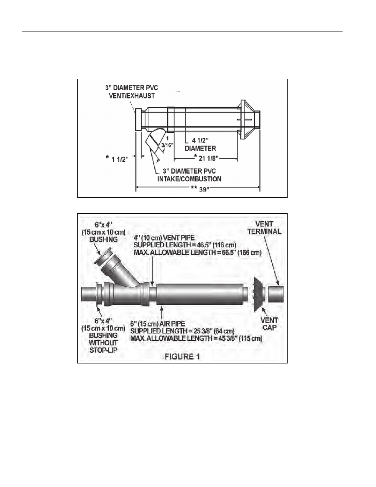
CONCENTRIC VENTING
Concentric venting allows for a single wall penetration. For multiple water heater installation using this vent
practice any additional vents of this type may be located 12" on centerline to either side of the first vent or
12" on centerline vertically above the first vent.
BTH Concentric Vent for 120 through 300.
BTH Concentric Vent for 400 through 500.

13
Servicing should only be performed by a Qualied Service Agent
VENT CONDENSATION
Failure to properly install the drain line on the condensate elbow will result in a water heater shut
down and a “blocked exhaust” fault message.
The average dew point of natural gas flue products is 127°F. Propane flue products is 119°F. With 70°F
ambient air temperature and 180°F stored water temperature, exhaust gas will be approximately 140°F.
Q. CAN I DRAIN THIS CONDENSATION TO THE FLOOR DRAIN?
A. The “Corrosion Resistance of Cast Iron Soil Pipe” by the Ductile Metals Association (formally the Cast
Iron Soil Pipe Institute) states that: “Internal corrosion of cast iron soil pipe and fittings can be caused by
strong acids or other reagents having an acidity of pH 4.3 or less if allowed to contact cast iron pipe for
an extended period of time without sufficient dilution to raise the pH valve about 4.3. By avoiding low pH
discharges, internal corrosion problems can be limited or eliminated, assuring the owner many years of
service.”
Q. WHAT ABOUT THE PH VALUES OF CONDENSATE AND SODA POP?
A. The pH of the BTH condensate average 4.5 which is approximately 4 times less concentrated than the
limit of 4.3 recommended by the DMA. Any water flow in the drain rapidly dilutes the condensate even
more. A can of leading carbonated cola drink measured a pH of 2.5 which is 300 times more concentrated
than the BTH condensate.
Q. WHAT DOES THE PH SCALE MEAN?
A. The PH value is a measure of acidity or alkalinity. A pH of 7 is neutral. Numbers from 7 to 1 indicate
increasing acidity and numbers from 7 to 14 indicate increasing alkalinity. The pH scale is similar to
the Richter scale used to measure earthquakes. Each number indicates a change of 10 times the
concentration of the previous value. A pH-6 is 10 times more concentrated than a pH-7, a pH-5 is (10x10)
100 times pH-7 and pH-4 is (10x10x10) 1,000 times pH-7, etc.
Q. WHAT ABOUT CONDENSATE NEUTRALIZERS?
A. Condensate neutralizers are usually not necessary. A condensate neutralizer is easy to make by filling
a short length of 2" or 3" PVC pipe with landscape marble chips, capping it and installing it in series with
the condensate drain of the equipment. Most commercial neutralizers are off the market because of poor
demand for the product. Condensation from the exhaust vent piping and tank internal flue way must be
allowed to drain. A “blocked flue” indication will often be your first indication that condensate is not draining.
 Loading...