


COPPER BOILERS
FOR HYDRONIC HEATING AND HOT WATER SUPPLY
•Installation
•Operation
•Maintenance
•Limited Warranty
WARNING: If the information in this manual is not followed exactly, a fire or explosion may result causing property damage, personal injury or loss of life.
—Do not store or use gasoline or other flammable vapors and liquids in the vicinity of this or any other appliance.
—WHAT TO DO IF YOU SMELL GAS:
•Do not try to light any appliance.
•Do not touch any electrical switch; do not use any phone in your building.
•Immediately call your gas supplier from a neighbor’s phone. Follow the gas supplier’s instructions.
•If you cannot reach your gas supplier, call the fire department.
—Installation and service must be performed by a qualified installer, service agency or the gas supplier.
CAUTION
TEXT PRINTED OR OUTLINED IN RED CONTAINS INFORMATION RELATIVE TO YOUR SAFETY. PLEASE READ THOROUGHLY BEFORE INSTALLING AND USING THIS APPLIANCE.
Instruction Manual
GB/GW-300, 400, 500, 650, 750 SERIES 400, 401, 402, 403, 404, 405
2-STAGE UNITS
You Thankfor buying this
cost efficient, high recovery unit
from A. O. Smith Water Products Company
Please read through this informative manual and pay special attention to the following:
ROUGH-IN DIMENSIONS/CAPACITIES PAGES 2 - 4 "FOREWORD" ON PAGE 5
"FEATURES" ON PAGES 6 - 7
"VENTING" ON PAGES 8 - 12
"GAS CONNECTIONS" 11 - 13
"INSTALLATION INSTRUCTIONS" ON PAGES 5 - 13 "WIRING DIAGRAM/SCHEMATIC" ON PAGES 14 - 15 "LIGHTING AND OPERATING" ON PAGES 19 - 20 "EMC5000 INSTRUCTIONS" ON PAGES 20 - 27 "SYSTEM EQUIPMENT INSTALLATION" PAGES 29 - 33 "TROUBLE SHOOTING" ON PAGES 27 - 28 "GENERAL MAINTENANCE" ON PAGES 34 - 35 "START-UP INSTRUCTIONS" ON PAGES 37 - 38 "LIMITED WARRANTY" ON PAGE 39
A DIVISION OFA. O. SMITH CORPORATION
MC BEE, SC., RENTON, WA.,
STRATFORD-ONTARIO, VELDHOVEN-THE NETHERLANDS www.hotwater.com
|
PLACE THESE INSTRUCTIONS ADJACENT TO BOILER AND |
|
PRINTED 0809 |
NOTIFY OWNER TO KEEP FOR FUTURE REFERENCE. |
212130-002 |
|
1

FIGURE2.
FRONT
FIGURE1.
LEFTSIDE
|
|
|
|
|
|
|
|
|
|
FIGURE |
3. |
|
|
|
|
|
|
|
|
|
|
|
|
|
|
||
|
|
|
|
|
|
|
|
|
|
TOP |
|
|
|
|
|
|
|
|
|
|
|
|
|
|
|
||
|
|
|
|
|
|
|
|
|
|
|
|
|
|
|
|
|
|
|
|
|
|
|
|
|
|||
TABLE 1A. BASIC GAS AND ELECTRICAL PARAMETERS |
|
|
|
|
|
|
|
|
|
|
|
|
|
|
|
|
|
||||||||||
|
|
|
|
|
|
|
MANIFOLD |
|
MANIFOLD |
|
|
|
|
|
|
|
|
|
|
|
|
|
|
|
|
||
MODEL |
|
TYPEOF |
|
|
|
|
|
PRESS. |
|
PRESS. |
|
|
|
|
|
|
|
|
|
|
|
|
|
|
|
|
|
GB/GW |
|
GAS |
|
VOLTS/HZ |
AMPS |
Inches W.C. |
|
kPa |
|
|
|
|
|
|
|
|
|
|
|
|
|
|
|
|
|
||
300 |
|
Natural |
|
120/60 |
20 |
|
3.5 |
|
0.87 |
|
|
|
|
|
|
|
|
|
|
|
|
|
|
|
|
|
|
400 |
|
Natural |
|
120/60 |
20 |
|
3.5 |
|
0.87 |
|
|
|
|
|
|
|
|
|
|
|
|
|
|
|
|
|
|
500 |
|
Natural |
|
120/60 |
20 |
|
3.5 |
|
0.87 |
|
|
|
|
|
|
|
|
|
|
|
|
|
|
|
|
|
|
650 |
|
Natural |
|
120/60 |
20 |
|
3.5 |
|
0.87 |
|
|
|
|
|
|
|
|
|
|
|
|
|
|
|
|
|
|
750 |
|
Natural |
|
120/60 |
20 |
|
3.5 |
|
0.87 |
|
|
|
|
|
|
|
|
|
|
|
|
|
|
|
|
|
|
300 |
|
Propane |
|
120/60 |
20 |
|
10.0 |
|
2.49 |
|
|
|
|
|
|
|
|
|
|
|
|
|
|
|
|
|
|
400 |
|
Propane |
|
120/60 |
20 |
|
10.0 |
|
2.49 |
|
|
|
|
|
|
|
|
|
|
|
|
|
|
|
|
|
|
500 |
|
Propane |
|
120/60 |
20 |
|
10.0 |
|
2.49 |
|
|
|
|
|
|
|
|
|
|
|
|
|
|
|
|
|
|
650 |
|
Propane |
|
120/60 |
20 |
|
10.0 |
|
2.49 |
|
|
|
|
|
|
|
|
|
|
|
|
|
|
|
|
|
|
750 |
|
Propane |
|
120/60 |
20 |
|
10.0 |
|
2.49 |
|
|
|
|
|
|
|
|
|
|
|
|
|
|
|
|
|
|
All Models - Maximum Supply Pressure: 14 In. W. C. (03.49 kPa) |
|
|
|
|
|
|
|
|
|
|
|
|
|
|
|
|
|
||||||||||
Minimum Supply Pressure Natural Gas: 4.5 In.W. C. ( 01.22 kPa) |
|
|
|
|
|
|
|
|
|
|
|
|
|
|
|
|
|
||||||||||
Minimum Supply Pressure Propane (LP) Gas: 11.0 In. W. C. ( 02.74 kPa) |
|
|
|
|
FIGURE4. |
|
|
|
|
|
|
|
|
||||||||||||||
|
|
|
|
|
|
|
|
|
|
|
|
|
|
|
|
|
|
|
|
|
|
|
|
|
|
||
TABLE1B. ROUGH-INDIMENSIONS |
|
|
|
|
|
|
|
|
|
|
REAR |
|
|
|
|
|
|
|
|
||||||||
|
|
|
|
|
|
|
|
|
|
|
|
|
|
|
|
|
|
|
|
||||||||
|
|
|
|
|
|
|
|
|
|
|
|
|
|
|
|
|
|
|
|
|
|
|
|
|
|
|
|
|
|
|
|
|
|
Btu/hr.Input |
KW Input |
Exhaust |
|
|
|
Water |
Gas |
|
|
|
|
|
|
|
|
|
|
|
|||
|
|
Btu/hr. Input |
|
KW Input |
Propane (LP) |
Propane (LP) |
Vent Size |
Inlet Air |
Connections |
Piping |
Width |
Width |
|
A |
A |
B |
B |
C |
C |
||||||||
Model |
Natural Gas |
|
Natural Gas |
Gas |
Gas |
(Inch) |
(Inch) |
Size (Inch) |
(Inch) |
|
(Inch) |
(mm) |
(inch) |
(mm) |
(Inch) |
(mm) |
(Inch) |
mm |
|||||||||
GB/GW 300 |
300,000 |
|
|
88 |
300,000 |
88 |
|
5 |
5 |
|
1 1/2 |
|
3/4 |
29 1/2 |
749 |
|
14 13/16 |
376 |
9 |
229 |
12 |
305 |
|||||
GB/GW 400 |
399,900 |
|
|
117 |
399,900 |
117 |
|
6 |
6 |
|
1 1/2 |
|
1 |
35 3/4 |
908 |
|
17 15/16 |
456 |
9 |
229 |
14 3/4 |
375 |
|||||
GB/GW 500 |
500,000 |
|
|
147 |
500,000 |
147 |
|
6 |
6 |
|
2 |
|
1 |
42 |
1067 |
|
21 |
1/16 |
535 |
9 |
229 |
14 3/4 |
375 |
||||
GB/GW 650 |
650,000 |
|
|
190 |
650,000 |
190 |
|
8 |
8 |
|
2 |
|
1 1/4 |
51 3/8 |
1305 |
|
25 3/4 |
654 |
9 |
229 |
14 3/4 |
375 |
|||||
GB/GW 750 |
750,000 |
|
|
220 |
750,000 |
220 |
|
8 |
8 |
|
2 |
|
1 1/4 |
57 5/8 |
1464 |
|
28 7/8 |
733 |
9 |
229 |
17 1/4 |
438 |
|||||
2

FIGURE5.
REAR
FIGURE6.
TOP
FIGURE7.
LEFT SIDE
|
|
|
|
FIGURE8. |
|
|
|
|
TABLE 1C. OUTDOOR UNIT DIMENSIONS |
|
FRONT |
|
|
|
|
||
|
|
|
|
|
|
|||
|
|
|
|
|
|
|
|
|
MODEL NUMBER |
A |
B |
C |
D |
E |
F |
G1 |
G2 |
GBO/GWO-300 |
3 |
9 3/4 |
49 |
13 5/8 |
34 5/8 |
67.88 |
24 3/16 |
— |
GBO/GWO-400 |
3 |
9 3/4 |
55 1/4 |
13 5/8 |
34 5/8 |
68.88 |
24 3/16 |
— |
GBO/GWO-500 |
3 |
9 3/4 |
61 1/2 |
13 5/8 |
34 5/8 |
68.88 |
24 3/16 |
— |
GBO/GWO-650 |
3 |
9 3/4 |
70 7/8 |
13 5/8 |
34 5/8 |
68.63 |
— |
27 11/16 |
GBO/GWO-750 |
3 |
9 3/4 |
77 1/8 |
13 5/8 |
34 5/8 |
68.63 |
— |
27 11/16 |
|
|
|
|
|
|
|
|
|
3

TABLE 2. PUMP PERFORMANCE
|
Water |
Flow Rate |
Head Loss |
Rise Temp. |
Pipe Size |
Pump |
|||
Model |
Category |
GPM |
LPM |
Feet |
Meter |
F |
C |
(Inch) |
Taco Models* |
GW-300 |
Normal |
17 |
64 |
4.4 |
1.3 |
30 |
2.4 |
1 1/2" |
0010 |
|
Hard |
25 |
95 |
9.5 |
2.9 |
20 |
5.3 |
1 1/2" |
0012 |
GW-400 |
Normal |
23 |
87 |
8.0 |
2.4 |
30 |
4.4 |
1 1/2" |
0012 |
|
Hard |
34 |
129 |
6.0 |
1.8 |
20 |
3.3 |
2" |
0012 |
GW-500 |
Normal |
28 |
106 |
4.6 |
1.4 |
30 |
2.6 |
2" |
0012 |
|
Hard |
42 |
159 |
9.1 |
2.8 |
20 |
5.1 |
2" |
1911 (1/4 HP) |
GW-650 |
Normal |
37 |
140 |
6.2 |
1.9 |
30 |
3.4 |
2" |
0012 |
|
Hard |
55 |
208 |
12.2 |
3.7 |
20 |
6.8 |
2" |
1911 (1/3 HP) |
GW-750 |
Normal |
42 |
159 |
9.7 |
3.0 |
30 |
5.4 |
2" |
1911 (1/4 HP) |
|
Hard |
63 |
238 |
18.8 |
5.7 |
20 |
10.4 |
2" |
1935 (1/3 HP) |
Pressure drop includes the loss through 50' (15.2M) of pipe and normal fittings, when installed with storage tank.
WATER CATEGORY |
GRAIN HARDNESS PER GAL. |
NORMAL |
1 THROUGH 15 |
HARD |
OVER 15 |
*Taco Pumps shown. Equivalent Armstrong, Bell & Gossett or Grundfos are acceptable as long as the flow rates are maintained. Always ensure adequate support for pump and piping.
TABLE 3. RECOVERYCAPACITIES
TABLE4. HEATEXCHANGERPRESSUREDROP
TEMPERATURERISEANDPRESSUREDROP
|
20 (oF) Rise |
30 (oF) Rise |
40 (oF) Rise |
10 (oC) Rise |
15 (oC) Rise |
20 (oC) Rise |
||||||
Model |
|
PD-Ft. |
|
PD-Ft. |
|
PD-Ft. |
|
PD-Meters |
|
PD-Meters |
|
PD-Meters |
GB |
Flow GPM |
Head |
Flow GPM |
Head |
Flow GPM |
Head |
Flow LPM |
Head |
Flow LPM |
Head |
Flow LPM |
Head |
300 |
25 |
1.3 |
17 |
0.6 |
13 |
0.4 |
95 |
0.38 |
64 |
0.19 |
49 |
0.12 |
400 |
34 |
2.2 |
23 |
0.9 |
17 |
0.6 |
129 |
0.67 |
87 |
0.28 |
64 |
0.20 |
500 |
42 |
3.4 |
28 |
1.8 |
21 |
0.9 |
159 |
1.03 |
106 |
0.54 |
79 |
0.29 |
650 |
55 |
3.5 |
37 |
2.0 |
27 |
1.8 |
208 |
1.07 |
140 |
0.61 |
102 |
0.56 |
750 |
63 |
8.3 |
42 |
4.3 |
32 |
2.1 |
238 |
2.53 |
159 |
1.31 |
121 |
0.64 |
4

FOREWORD
 CAUTION
TEXT PRINTED OR OUTLINED IN RED CONTAINS INFORMATION RELATIVE TO YOUR SAFETY. PLEASE READ COMPLETELY BEFORE USING APPLIANCE.
Detailed installation diagrams are in this manual. These diagrams will provide the installer with a reference of materials needed and a suggested method of piping. IT IS NECESSARY THAT ALL WATER AND GAS PIPING, AND THE ELECTRICAL WIRING BE INSTALLED AND CONNECTED AS SHOWN IN THE DIAGRAMS.
CHECK THE DIAGRAMS THOROUGHLY BEFORE STARTING INSTALLATION TOAVOID POSSIBLE ERRORSAND TO MINIMIZE TIME AND MATERIALS COST. SEE FIGURES 1 THROUGH 4 AND TABLES 1A, 1B AND 1C.
This design complies with the current edition of ANSI Z21.13 - CSA 4.9 for Gas-Fired Low-Pressure Steam and Hot Water Boilers.
MAKE SURE THE GAS ON WHICH THE BOILER WILL OPERATE IS THE SAME AS THAT SPECIFIED ON THE BOILER RATING PLATE.
The boiler installation must conform to these instructions and the requirements of the local authority having jurisdiction.
In the absence of local code requirements, the installation must conform to the National Fuel Gas Code, ANSI Z223.1 or CAN/ CSA-B149.1-00 (current edition).
These manuals can be purchased from the Canadian Standards Association, 8501 East Pleasant Valley Road, Cleveland, OH 44131
.
REPLACEMENT PARTS
Replacement parts may be ordered through A. O. Smith dealers, authorized servicers or distributors. Refer to the Yellow Pages for where to call or contact (in United States) the A. O. Smith Water Products Company, 500 Tennessee Waltz Parkway, Ashland City, TN 37015, 1-800-433-2545 or (in Canada) A. O. Smith Enterprises Ltd., 768 Erie Street, Stratford, Ontario, Canada N5A 6T3, 800-265-8520. When ordering parts be sure to state the quantity, part number and description of the item including the complete model and serial number as it appears on the product. Refer to the parts lists for more information.
For Technical Assistance call A. O. Smith Technical Information Center at 1-800-527-1953.
 WARNING
THE WATER MANIFOLD IS NOT DESIGNED TO SUPPORT THE WEIGHT OF THE WATER PIPING SYSTEM. AS ON ALL BOILER INSTALLATIONS, SPECIAL CARE MUST BE TAKEN TO ENSURE PROPER SUPPORT.
 WARNING
UNDER NO CIRCUMSTANCES SHOULD THE EQUIPMENT ROOM WHERE THE BOILER IS INSTALLED EVER BE UNDER NEGATIVE PRESSURE. PARTICULAR CARE MUST BE TAKEN WHEN EXHAUST FANS, COMPRESSORS, AIR HANDLING EQUIPMENT, ETC., MAY INTERFERE WITH THE COMBUSTION AND VENTILATION AIR SUPPLIES OF THIS BOILER.
 CAUTION
Label all wires prior to disconnection when servicing controls. Wiring errors can cause improper and dangerous operation of the boiler.
"Verify proper operation after servicing."
INSTALLATION CLEARANCES
Sufficient area should be provided at the front (2 feet minimum) and at the water connection side (1 foot minimum) of the unit for proper servicing. Sufficient clearance should be provided at the return header side of the boiler to permit access to heat exchanger tubes for cleaning. In a utility room installation, the door shall be wide enough to allow the boiler to enter or to permit the replacement of another appliance.
These boilers are approved for installation on noncombustible flooring in an alcove with minimum clearance to combustibles of:
3 inches sides, and back; 3 inches top, front alcove, 6 inches vent.
For installation on combustible flooring use the Combustible Floor Kit. The combustible floor kit base adds 4" to the overall height of the boiler, see Figure 9.
FIGURE9. BOILERONCOMBUSTIBLEFLOORBASE
Model |
Combustible Floor Kit |
(GB/GW)-300 |
210202-001 |
(GB/GW)-400 |
210202-002 |
(GB/GW)-500 |
210202-003 |
(GB/GW)-650 |
210202-004 |
(GB/GW)-750 |
210202-005 |
Two inch clearance is required from combustible construction to hot water pipes.
LEVELLING
Each unit must be checked after installation to be certain that it is level.
CONDENSATION WARNING
Your boiler is not designed to operate with a boiler inlet water temperature of less than 120°F (38°C). Colder inlet water temperatures will result in significant condensation developing on the heat exchanger. This situation can cause a corrosive environment for the heat exchanger, burners and venting resulting in premature damage, which could result in serious personal injury or death. Damage caused by excessive condensation will not be covered under the limited warranty.
For systems that use large volumes of cold water or systems utilizing heavy water draws, condensation can be prevented by using a bypass loop.
5
FEATURES
IMPORTANT
Only qualified personnel shall perform the initial firing of the heater. At this time the user should not hesitate to ask the start-up technician any questions regarding the operation and maintenance of the unit.
Lighting and Operating instructions are included with this manual. By using these instructions, the user may be able to make minor operational adjustments and save unnecessary service calls. However, the user should not attempt repairs, but should contact a service technician or gas supplier.
SAFETY RELIEF VALVES
Your local code authority may have other specific relief valve requirements not covered below.
 WARNING
THE PURPOSE OF A SAFETY RELIEF VALVE IS TO AVOID EXCESSIVE PRESSURE WHICH MAY CAUSE TANK EXPLOSION, SYSTEM OR BOILER DAMAGE.
TO AVOID WATER DAMAGE A DRAIN LINE MUST BE CONNECTED TO A SAFETY RELIEF VALVE TO DIRECT DISCHARGE TO A SAFE LOCATION. A DRAIN LINE MUST NOT BE REDUCED FROM THE SIZE OF THE VALVE OUTLETAND IT MUST NOT CONTAINANY VALVES BETWEEN THE BOILERAND THE RELIEF VALVE OR THE RELIEF VALVE AND THE DRAIN EXIT. IN ADDITION, THERE SHOULD NOT BE ANY RESTRICTIONS IN A DRAIN LINE NOR SHOULD IT BE ROUTED THROUGH AREAS WHERE FREEZING CONDITIONS MIGHT OCCUR. DO NOT THREAD OR CAP THE DRAIN LINE EXIT. RESTRICTING OR BLOCKING ADRAIN LINE WILL DEFEAT THE PURPOSE OF THE RELIEF VALVEAND MAY CREATEAN UNSAFE CONDITION. INSTALL A DRAIN LINE WITH A DOWNWARD SLOPE SUCH THAT IT NATURALLY DRAINS ITSELF.
If any safety relief valve is replaced, the replacement valve must comply with the latest version of the ASME Boiler and Pressure Vessel Code, Section IV (HEATING BOILERS). Select a relief valve with a discharge rating NOT less than the boiler input, and a set pressure NOT exceeding the working pressure of any component in the system.
The storage tank temperature and pressure relief valve must comply with the applicable construction provisions of the Standard for Relief Valves for Hot Water Supply Systems, ANSI Z21.22 - CSA 4.4 (current edition). The valve must be of the automatic reset type and not embody a single-use type fusible plug, cartridge or linkage.
FOR HOT WATER HEATING SYSTEMS, the boilers are shipped with a 50 psi pressure relief valve. This relief valve is factory installed in the water outlet header of the boiler, see Figure 1.
FOR HOT WATER SUPPLY SYSTEMS, the boilers are shipped with a 125 psi pressure relief valve. This relief valve is factory installed in the water outlet header of the boiler, see Figure 1.
This ASME-rated valve has a discharge capacity that exceeds the maximum boiler input rating and a pressure rating that does not exceed the maximum working pressure shown on the boiler rating plate.
In addition, a CSA design-certified and ASME-rated temperature and pressure (T & P) relief valve must be installed on each and every water storage tank in the hot water supply system.
The T & P relief valve should have a temperature rating of 210°F, a pressure rating NOT exceeding the lowest rated working pressure of any system component, and a discharge capacity exceeding the total input of the water boilers supplying water to the storage tank.
Locate the T & P relief valve (a) in the top of the tank, or (b) in the side of the tank on a center line within the upper six (6) inches of the top of the tank, see Figure 20 and 22. The tapping shall be threaded in accordance with the latest edition of the Standard for Pipe Threads, General Purpose (inch), ANSI/ASME B1.20.1. The location of, or intended location for, the T & P relief valve shall be readily accessible for servicing or replacement.
INSTALLATION INSTRUCTIONS
REQUIRED ABILITY
INSTALLATION OR SERVICE OF THIS BOILER REQUIRES ABILITY EQUIVALENT TO THAT OF A LICENSED TRADESMAN IN THE FIELD INVOLVED. PLUMBING, AIR SUPPLY, VENTING, GAS SUPPLY AND ELECTRICAL WORK ARE REQUIRED.
LOCATION
When installing the boiler, consideration must be given to proper location. Location selected should be as close to the stack or chimney as practical with adequate air supply and as centralized with the piping system as possible. This location should also be such that the gas ignition system components are protected from water (dripping, spraying, etc.) during appliance operation and service [circulator replacement, control replacement, etc.].
•THE BOILER MUST NOT BE INSTALLED ON CARPETING.
•THE BOILER SHOULD NOT BE LOCATED INANAREAWHERE IT WILL BE SUBJECT TO FREEZING.
•THE BOILER SHOULD BE LOCATED NEAR A FLOOR DRAIN.
•THE BOILER SHOULD BE LOCATED IN AN AREA WHERE LEAKAGE FROM THE BOILER OR CONNECTIONS WILL NOT RESULT IN DAMAGE TO THE ADJACENT AREA OR TO LOWER FLOORS OF THE STRUCTURE.
WHEN SUCH LOCATIONS CANNOT BE AVOIDED, A SUITABLE DRAIN PAN SHOULD BE INSTALLED UNDER THE BOILER. Such pans should be fabricated with sides at least 2-1/2" deep, with length and width at least 2" greater than the dimensions of the boiler plus piping connections and must be piped to an adequate drain. The pan must not restrict combustion air flow.
 WARNING
THERE IS A RISK IN USING FUEL BURNING APPLIANCES IN ROOMS OR AREAS WHERE GASOLINE, OTHER FLAMMABLE LIQUIDS OR ENGINE DRIVEN EQUIPMENT OR VEHICLES ARE STORED, OPERATED OR REPAIRED. FLAMMABLE VAPORS ARE HEAVY AND TRAVEL ALONG THE FLOOR AND MAY BE IGNITED BY THE IGNITER OR MAIN BURNER FLAMES CAUSING FIRE OR EXPLOSION. SOME LOCAL CODES PERMIT OPERATION OF GAS APPLIANCES IF INSTALLED 18 INCHES OR MORE ABOVE THE FLOOR. THIS MAY REDUCE THE RISK IF LOCATION IN SUCH AN AREA CANNOT BE AVOIDED.
FLAMMABLE ITEMS, PRESSURIZED CONTAINERS OR ANY OTHER POTENTIAL FIRE HAZARDOUSARTICLES MUST NEVER BE PLACED ON OR ADJACENT TO THE BOILER.
OPEN CONTAINERS OF FLAMMABLE MATERIAL SHOULD NOT BE STORED OR USED IN THE SAME ROOM WITH THE BOILER.
6
If the boiler is installed above the level of heating system terminal units, a low water cutoff device must be installed in the boiler outlet at the time of installation.
CHEMICAL VAPOR CORROSION
Heat exchanger corrosion and component failure can be caused by the heating and breakdown of airborne chemical vapors. Spray can propellants, cleaning solvents, refrigerator and air conditioning refrigerants, swimming pool chemicals, calcium and sodium chloride, waxes, and process chemicals are typical compounds which are corrosive. These materials are corrosive at very low concentration levels with little or no odor to reveal their presence.
Products of this sort should not be stored near the boiler. Also, air which is brought in contact with the water boiler should not contain any of these chemicals. If necessary, uncontaminated air should be obtained from remote or outside sources.
MANUAL RESET HIGH TEMPERATURE LIMIT CONTROL
This device prevents the water temperature from reaching 250°F. This device is located in the outlet temperature probe.
AUTOMATIC RESET
HIGH TEMPERATURE LIMIT CONTROL
 CAUTION
LIMIT CONTROLS ARE NOT TO BE USED AS A THERMOSTAT.
This device prevents the outlet water temperature from reaching the setpoint. Its operation is based on the feedback from the outlet temperature probe. If the temperature exceeds the setpoint, a fault is declared and the gas is shut off. The fault condition is automatically cleared when the temperature drops below the high limit setpoint minus the high limit differential. The factory preset values (and the default high limit values) are 210°F for GW models and 230°F for GB models. The user can adjust these values between 90°F and 210°F for the GW models and 90°F and 235°F for the GB models. The factory preset value (and the default high limit differential value) for both models is 20°F. The user adjustable range is 1°F to 50°F.
TANK PROBE/INLET PROBE
FOR HOT WATER SUPPLY SYSTEMS (GW models),A tank probe is supplied with each hot water supply boiler. When a tank probe is connected to the system, the tank section on the UIM temperature screen will display a temperature instead of dashes.
"Pigtails" of field-supplied wires should be spliced to "pigtails" of tank probe and to "pigtails" at the junction box. See Figure 21 for the tank probe installation. Operating control of the system will be transferred to the tank probe when "Tank Cont" is selected on dip switch #3 off "SW1" on the CCB.
In the absence of tank probe, the inlet probe can be used for boiler stage control. Staging control will be transferred to inlet probe when "Inlet" is selected on dip switch #3 on CCB. Make sure to set the boiler pump for continuous operation.
FOR HOT WATER HEATING SYSTEMS (GB models) Due to the various types of systems and operating conditions, no factory operating control is supplied with the GB models. If no probe is attached to the system, then the dip switch on the CCB should be set to inlet control (and make sure that boiler pump is set for
continuous operation). GB models require a field supplied operating control be installed in the system. Such as: loop stat, indoor/outdoor reset control, sequencing panel, or energy management system. These types of controls connect to the thermostat wires in the junction box on the boiler. Do not operate this boiler using the internal high limits only, you must use an operating stat as mentioned above.
CIRCULATING PUMP
The pump flow rate should not exceed the maximum recommended flow rate, see Table 2.
FOR HOT WATER SUPPLY SYSTEMS (GW models), the circulating pump is an integral part of the Boiler, see Figure 3. This pump has been lubricated at the factory, and future lubrication should be in accordance with the motor manufacturer's instructions provided as supplement to this manual.
FOR HOT WATER HEATING SYSTEMS (GB models), the circulating pump is NOT provided and must be field-installed.
SAFETY FLOW SWITCH (Supplied)
The safety flow switch is a safety device which is installed at the water outlet of the unit to prevent main burner operation in the event of inadequate water flow through the boiler.
This switch is connected to the CCB, and its status is displayed on the "System Status" screen. An asterisk indicates switch closure (water flowing).
LOW WATER CUTOFF (OPTIONAL)
If low water protection is required by the authorities having jurisdiction, a low water cutoff switch should be installed next to the boiler in the outlet water line as shown in Figure 23. To meet code requirements the power connections for this switch can be connected to the LWCO connections on the CCB, but the independent contacts for feedback should not be. They should be connected in series with the ECO. When connected in this manner, the LWCO dipswitch on the CCB should be off. The system will not recognize a low water fault condition as a LWCO fault. It will respond with an ECO fault. The switch should receive periodic (every six months) inspection to assure proper operation. A low water cutoff device of the float type should be flushed every six months. If a LWCO is desired, but not required by code, it can be connected to the LWCO connections on the CCB and the dipswitch should be turned to on. The system will then recognize a low water fault condition as LWCO fault.
DRAIN VALVE (Not Supplied)
Drain valves must be obtained and installed on each boiler and tank for draining purposes.
AIR REQUIREMENTS
 WARNING
FOR SAFE OPERATION, AN AMPLE SUPPLY OF AIR MUST BE PROVIDED FOR PROPER COMBUSTIONAND VENTILATION IN ACCORDANCE WITH THE NATIONAL FUEL GAS CODE, ANSI Z223.1 OR CAN/CSA-B149.1 (CURRENT EDITIONS) OR APPLICABLE PROVISIONS OF THE LOCAL BUILDING CODES. AN INSUFFICIENT SUPPLY OF AIR MAY RESULT IN A YELLOW, LUMINOUS BURNER FLAME, CARBONING OR SOOTING OF THE FINNED HEAT EXCHANGER, OR CREATE A RISK OF ASPHYXIATION. DO NOT OBSTRUCT THE FLOW OF COMBUSTIONAND VENTILATION AIR.
7

UNCONFINED SPACE
In buildings of conventional frame, brick or stone construction, unconfined spaces may provide adequate air for combustion.
If the unconfined space is within a building of tight construction (buildings using the following construction: weather stripping, heavy insulation, caulking, vapor barrier, etc.), air for combustion, ventilation, must be obtained from outdoors or spaces freely communicating with the outdoors. The installation instructions for confined spaces in tightly constructed buildings must be followed to ensure adequate air supply.
CONFINED SPACE
(a) U. S. INSTALLATIONS
When drawing combustion and dilution air from inside a conventionally constructed building to a confined space, such a space shall be provided with two permanent openings, ONE WITHIN 12 INCHES OF THE ENCLOSURE TOP AND ONE WITHIN 12 INCHES OF THE ENCLOSURE BOTTOM. Each opening shall have a free area of at least one square inch per 1000 Btuh of the total input of all appliances in the enclosure, but not less than 100 square inches.
If the confined space is within a building of tight construction, air for combustion, ventilation, and draft hood dilution must be obtained from outdoors. When directly communicating with the outdoors or communicating with the outdoors through vertical ducts, two permanent openings, located in the above manner, shall be provided. Each opening shall have a free area of not less than one square inch per 4000 Btuh of the total input of all appliances in the enclosure. If horizontal ducts are used, each opening shall have a free area of not less than one square inch per 2000 Btuh of the total input of all appliances in the enclosure.
(b) CANADIAN INSTALLATIONS
Ventilation of the space occupied by the boiler(s) shall be provided by an opening for ventilation air at the highest practical point communicating with outdoors. The total cross-sectional area shall be at least 10% of the area of the combustion air opening but in no case shall the cross-sectional area be less than 10 square inches (6500 mm2).
In addition to the above, there shall be permanent air supply opening(s) having a cross-sectional area of not less than 1 square inch per 7,000 BTUH (310 mm2/KW) up to and including 1,000,000 BTUH plus 1 square inch per 14,000 BTU in excess of 1,000,000 BTUH. This opening(s) shall be located at, or ducted to, a point neither more than 18" (450 mm) nor less than 6 inches (150 mm) above the floor level.
Where power vented equipment is used in the same room as the boiler, sufficient air openings must be supplied.
UNDERSIZED OPENINGS MAY RESULT IN INSUFFICIENT AIR FOR COMBUSTION.
Where an exhaust fan is installed in the same room with a boiler, sufficient openings for air must be provided in the walls. UNDERSIZED OPENINGS WILL CAUSEAIR TO BE DRAWN INTO THE ROOM THROUGH THE CHIMNEY, CAUSING POOR COMBUSTION. SOOTING MAY RESULT WITH AN INCREASED RISK OFASPHYXIATION.
VENTING THE BOILER
This boiler is approved to be vented as a Category I, Category III (horizontal venting), or a Direct Vent appliance. The Horizontal and Direct Venting options require a special vent kit.
TABLE 5.
Horizontal Vent or |
|
Horizontal Direct Vent Kit |
Model Number |
210320-001 |
G(W,B) 300 |
210320-002 |
G(W,B) 400 |
210320-002 |
G(W,B) 500 |
210320-003 |
G(W,B) 650 |
210320-003 |
G(W,B) 750 |
|
|
Vertical Direct Vent Kit |
Model Number |
210317-001 |
G(W,B) 300 |
210317-002 |
G(W,B) 400 |
210317-002 |
G(W,B) 500 |
210317-003 |
G(W,B) 650 |
210317-003 |
G(W,B) 750 |
 CAUTION
When venting the Genesis Boiler through oversize chimney (including masonry chimneys), additional care must be exercised to assure proper draft. For proper operation, a minimum draft of -0.02" w.c. and a maximum draft of -0.04" w.c. must be maintained. In instances of excessive draft, a barometric damper may be required to assist in maintaining the proper draft. Draft should be measured 2 feet above the boiler vent collar. The vent system must not have external runs greater than that allowed by local codes or the National Fuel Gas Code.
WARNING
THE INSTRUCTIONS IN THIS SECTION ON VENTING THE BOILER MUST BE FOLLOWED TOAVOID CHOKED COMBUSTION OR RECIRCULATION OF FLUE GASES. SUCH CONDITIONS CAUSE SOOTING OR RISKS OF FIREANDASPHYXIATION.
STANDARD (VERTICAL) VENTING, CATEGORY I
THIS BOILER MAYBE VENTEDACCORDING TOTABLE 5AAND 5C (ALSOSEEFIGURE6). ATLEASTTYPEBVENTINGMUSTBEUSED WITHTHE STANDARD VENTING OPTION (thru-the-roof) USINGTHE NATIONAL FUEL GAS CODE VENT TABLES.* TYPE B VENT PIPE CANNOT BE USED IF THE BOILER IS VENTED HORIZONTALLY (SEE PAGES 10AND 11). ALLLOCALUTILITY, STATE/PROVINCIAL, REGULATIONS ON VENTING MUST BE FOLLOWED.
VENT SIZING, INSTALLATION AND TERMINATION SHALL BE IN ACCORDANCE WITH THE NATIONAL FUEL GAS CODE, ANSI Z223.1 OR CAN/CSA-B149.1 (CURRENT EDITIONS).
VENT CONNECTION
Model Number |
Vent Connector |
G(W,B) 300 |
5" |
G(W,B) 400 |
6" |
G(W,B) 500 |
6" |
G(W,B) 650 |
8" |
G(W,B) 750 |
8" |
*For vent arrangements other than Table 5A and for proper boiler operation, a barometric damper is required to maintain draft between -0.02" w.c. and -0.04" w.c at 2 feet above the boiler vent collar.
8

FIGURE 10. SINGLE PIPE VERTICALTERMINATION
Vent connections must be made to an adequate stack or chimney and shall be in accordance with the National Fuel Gas Code, ANSI Z223.1 or CAN/CSA-B149.1 applicable provisions of the local building codes. Size and install proper size vent pipe.
Horizontal runs of vent pipe shall be securely supported by adequately placed (approximately every 4 feet), noncombustible hangers suitable for the weight and design of the materials employed to prevent sagging and to maintain a minimum upward slope of 1/4" per foot from the boiler to the vent terminals. Dampers or other obstructions must not be installed in the vent. Be sure that the vent connector does not extend beyond the inside wall of the chimney.
CONNECTING BOILER TO A COMMON VENT
 CAUTION
When the GENESIS boilers are commonly vented, additional care must be exercised to assure proper draft. For proper operation, a minimum draft of -0.02" w.c. and a maximum draft of -0.04" w.c. must be maintained AT EACH INDIVIDUAL BOILER. In instances of excessive draft, a barometric damper may be required to assist in maintaining the proper draft. Draft should be measured 2 feet above EACH boiler vent collar.
Do not connect the boiler to a common vent or chimney with solid fuel burning equipment. This practice is prohibited by most local building codes as is the practice of venting gas fired equipment to the duct work of ventilation systems.
Where a separate vent connection is not available and the vent pipe from the boiler must be connected to a common vent with an oil burning furnace, the vent pipe should enter the common vent or chimney at a point ABOVE the flue pipe from the oil furnace.
UL/ULC listed double wall type B-1 gas vents, through 8" diameter, can be installed in heated and unheated areas and can pass through floors, ceilings, partitions, walls and roofs, provided the required clearance is observed.
At the time of removal of an existing boiler, the following steps shall be followed with each appliance remaining connected to the common venting system. Perform these steps while the other appliances remaining connected to the common venting system are not in operation.
Seal any unused openings in the common venting system.
Visually inspect the venting system for proper size and horizontal pitch and determine there is not blockage or restriction, leakage, corrosion and other deficiencies which could cause an unsafe condition.
All boiler venting systems shall be installed in accordance with the National Fuel Gas Code, ANSI Z223.1 or CAN/CSA-B149.1 (current edition), or applicable provisions of the local building codes.
SINGLE PIPE HORIZONTALVENTING
Vent sizing, installation and termination shall be in accordance with the NATIONAL FUEL GAS CODE, ANSI Z223.1 OR CAN/CSAB149.1. If applicable, all local, utility, state/provincial regulations on venting must be followed. This boiler may be vented according to Table 5A and 5C. The exhaust vent pipe must be "Saf-T-Vent" manufactured by Heat-Fab Inc. The exhaust vent material type is AL 29-4C. This vent system must be 100% sealed with a condensate trap located as close to the boiler as possible.
FIGURE 11. SINGLE PIPE HORIZONTALTERMINATION
TABLE 5A. SINGLE PIPE HORIZONTALAND VERTICALVENTING
MODEL |
EXHAUSTVENT* |
GB/GW-300 |
110' |
GB/GW-400 |
50' |
GB/GW-500 |
50' |
GB/GW-650 |
50' |
GB/GW-750 |
50' |
*When sizing exhaust piping and intake air piping, 90-degree elbows are equivalent to 5 feet of straight pipe and 45-degree elbows are equal to 3 feet of straight pipe.
Intake/Exhaust Installation Requirements:
1.The termination must be a minimum of 12 inches above anticipated snow or grade level whichever is higher.
2.Due to normal formation of water vapor in the combustion process, horizontal terminations must not be located over areas of pedestrian or vehicular traffic, (e.g., public walkways or over areas where condensate could create a nuisance or hazard. This is especially true in colder climates where ice buildup is likely to occur. A.O. Smith Corporation will not be held liable for any personal injury or property damage due to any dislodging of ice.
3.The minimum distance from the exhaust terminal to any window, gravity air inlet to a building, or from gas or electric meter(s) is 6 feet horizontally, 4 feet below and 2 feet above.
4.The minimum distance from the exhaust terminal to an inside corner formed by two exterior walls is 6 feet but 10 feet is recommended where possible.
5.Maintain a minimum distance of 4 feet from any soffit or eave vent to the exhaust terminal.
6.Maintain a minimum distance of 10 feet from any forced air inlet to a building. Any fresh air or make up air inlet such as a dryer or furnace area is considered to be a forced air inlet.
7.Avoid areas where condensate drainage may cause problems such as above planters, patios, or adjacent to windows where the steam from the flue gases may cause fogging.
9

8.Select the point of wall penetration where the minimum 1/4" per foot of slope up can be maintained.
9.The through the wall termination kit is suitable for zero clearance to combustible materials.
10.The mid point of the exhaust and intake air termination elbows must be a minimum of 12 inches from the exterior wall.
DIRECT VENT HORIZONTALAND VERTICAL VENTING
Vent sizing, installation and termination shall be in accordance with the NATIONAL FUEL GAS CODE, ANSI Z223.1 OR CAN/ CSA-B149.1 (CURRENT EDITIONS). If applicable, all local, utility, state/provincial regulations on venting must be followed. This boiler may be vented according to Table 5B and 5C. The exhaust vent pipe must be "Saf-T-Vent" manufactured by Heat-Fab Inc. The exhaust vent material type is AL 29-4C. This vent system must be 100% sealed with a condensate trap located as close to the boiler as possible.
The intake air piping can be PVC, CPVC, ABS or any suitable intake air piping that can be sealed.
TABLE 5B. DIRECT VENT HORIZONTALAND VERTICALVENTING
MODEL |
INTAKE* |
EXHAUST* |
GB/GW-300 |
60' |
60' |
GB/GW-400 |
35' |
35' |
GB/GW-500 |
35' |
35' |
GB/GW-650 |
35' |
35' |
GB/GW-750 |
35' |
35' |
*When sizing exhaust piping and intake air piping, 90-degree elbows are equivalent to 5 feet of straight pipe and 45-degree elbows are equal to 3 feet of straight pipe.
Intake/Exhaust Installation Requirements:
1.The exhaust and intake air termination must be a minimum of 12 inches above anticipated snow or grade level which ever is higher, see Figure 14.
2.Due to normal formation of water vapor in the combustion process, horizontal terminations must not be located over areas of pedestrian or vehicular traffic, (e.g. public walkways or over areas where condensate could create a nuisance or hazard). This is especially true in colder climates where ice buildup is likely to occur. A.O. Smith Corporation will not be held liable for any personal injury or property damage due to any dislodging of ice.
3.The minimum distance from the exhaust terminal to any window, gravity air inlet to a building, or from gas or electric meter(s) is 6 feet horizontally, 4 feet below and 2 feet above.
4.The minimum distance from the exhaust terminal to an inside corner formed by two exterior walls is 6 feet but 10 feet is recommended where possible.
5.Maintain a minimum distance of 4 feet from any soffit or eave vent to the exhaust terminal.
6.Maintain a minimum distance of 10 feet from any forced air inlet to a building. Any fresh air or make up air inlet such as a dryer or furnace area is considered to be a forced air inlet.
7.Avoid areas where condensate drainage may cause problems such as above planters, patios, or adjacent to windows where the steam from the flue gases may cause fogging.
8.Select the point of wall penetration where the minimum 1/4" per foot of slope up can be maintained.
9.The through the wall termination kit is suitable for zero clearance to combustible materials.
10.The mid point of the exhaust and intake air termination elbows must be a minimum of 12 inches from the exterior wall.
10
 CAUTION
Direct venting into dead air spaces such as alleys, atriums and inside corners can cause recirculation of flue gases. Recirculation of flue gases will cause sooting, premature failure of the heat exchanger and icing of the combustion air intake during severe cold weather. To prevent the recirculation of flue gases, maintain as much distance as possible between the combustion air intake and the exhaust vent terminal.
FIGURE 12. DIRECT VENT HORIZONTALTERMINATIONAND MINIMUM CLEARANCES
FIGURE 13. DIRECT VENT HORIZONTAL/VERTICALTERMINATION
FIGURE 14. DIRECT VENT VERTICAL/HORIZONTALTERMINATION
FIGURE 15. DIRECT VENT VERTICALTERMINATIONAND
MINIMUM CLEARANCES
TABLE 5C. INTAKE/VENTING CONFIGURATIONS, CATEGORIESAND MATERIALS
Source for Combustion |
Exhaust Venting |
Venting Category |
Approved Venting |
Combustion Air |
Air Supply |
Configuration |
|
Material Required |
Intake Material |
|
|
|
Type B Vent Pipe* |
None |
Boiler Room Air (Using |
Vertical Natural Draft |
Category I |
(Requires a single-acting, |
Required |
combustion air from within |
|
|
listed barometric damper if vent |
|
the building.) |
|
|
length exceeds Table 5A.) |
|
|
Horizontal/Sidewall |
Category III |
AL29-4C Stainless Steel |
None |
|
Venting |
|
Vent Pipe** |
Required |
Direct Venting (Outside |
Vertical Direct Venting |
Category I |
AL29-4C Stainless Steel |
PVC,ABS, CPVC** |
combustion air thru sealed |
|
|
Vent Pipe** |
|
pipe to boiler intake.) |
Horizontal Direct |
Category III |
AL29-4C Stainless Steel |
PVC,ABS, CPVC** |
|
Venting |
|
Vent Pipe** |
|
Ducted Air*** (Using |
|
|
Type B Vent Pipe* |
|
combustion air from outside |
Vertical Natural Draft |
Category I |
(Requires a single-acting, |
PVC,ABS, CPVC, |
the building ducted |
|
|
listed barometric damper if vent |
Galvanized Metal Duct |
to boiler intake.) |
|
|
length exceeds Table 5A.) |
Pipe** |
NOTES: * A standard list type B vent terminal as supplied by the vent pipe manufacturer may be used.
**Vent cap/vent terminations and combustion air intake terminations must be furnished by the boiler manufacturer in accordance with CSA requirements. No substitutions; unapproved substitutions may/will result in dangerous conditions, nuisance lockouts during windy conditions and premature boiler failure.
***Cannot be used in rooms with negative pressure.
FLUE BOX INSTALLATION
This boiler can be vented and/or bring in fresh air through the rear of the cabinet with the use of the FLUE BOX and vent adaptor. Any of the previous venting configurations can be installed with rear connections.
4.Reinstall the jacket top and attach the cover plate (along with its gasket).
5.CAREFULLY cut the exhaust hole through the exposed fluebox insulation on the back of the fluebox. Dispose of the cut round piece of insulation.
6.Place the vent collar in alignment with the newly-cut exhaust hole and drill screw holes through the fluebox, using the vent collar as a template. Secure in place (along with its gasket) with the existing sheet metal screws.
To change the unit to rear intake air:
1.The vent collar (for intake air) and the cover plate (for intake air) must be switched. Insure all sheet metal screws are back in place.
GAS CONNECTIONS
FIGURE 16. STANDARD INSTALLATION
FIGURE 17. REAR VENT INSTALLATION
To change the unit to rear exhaust:
1.REFER TO THE PSD PARTS LIST, PART NO. 212131-000, AND ORDER THE "FLUE BOX INSULATION" (211909-007 FOR THE -300 MODEL; 211909-008 FOR THE 400 & 500 MODEL/ 211909-009 FOR THE 650 & 750 MODEL). THIS PART MUST BE IN HAND BEFORE PROCEEDING TO STEP 2.
2.Remove the vent collar, vent collar gasket, jacket top (from the top) and remove the cover plate and cover plate gasket (from the rear).
3.Remove as thoroughly as possible the fluebox insulation on top of the fluebox. REPLACE this part by applying hightemperature spray adhesive on the newly ordered part and adhering to the top of the fluebox.
 WARNING
THIS BOILER IS NOT INTENDED TO OPERATE AT GAS SUPPLY PRESSURE OTHER THAN SHOWN ON THE RATING PLATE. A LOCK-UP OR POSITIVE SHUT-OFF TYPE REGULATOR MUST BE INSTALLED IN THE GAS SUPPLY LINE. EXPOSURE TO HIGHER GAS SUPPLY PRESSURE MAY CAUSE DAMAGE TO GAS VALVES WHICH CAN RESULT IN FIRE OR EXPLOSION. IF OVERPRESSURE HAS OCCURRED SUCH AS THROUGH IMPROPER TESTING OF GAS LINES OR EMERGENCY MALFUNCTION OF THE SUPPLY SYSTEM, THE GAS VALVES MUST BE CHECKED FOR SAFE OPERATION. MAKE SURE THAT THE OUTSIDE VENTS ON THE SUPPLY REGULATORS AND THE SAFETY VENT VALVES ARE PROTECTED AGAINST BLOCKAGE. THESEARE PARTS OF THE GAS SUPPLY SYSTEM, NOT THE BOILER. VENT BLOCKAGE MAY OCCUR DURING ICE BUILD-UP OR SNOW STORMS.
WHEN LOCAL CODES REQUIRE A MAIN MANUAL SHUT-OFF VALVE OUTSIDE THE BOILER JACKET, A SUITABLE MAIN MANUAL SHUT-OFF VALVE MUSTBE INSTALLED INALOCATION COMPLYING WITH THOSE CODES.
IT IS IMPORTANT TO GUARD AGAINST GAS VALVE FOULING FROM CONTAMINANTS IN THE GAS WAYS. SUCH FOULING MAY CAUSE IMPROPER OPERATION, FIRE OR EXPLOSION. IF COPPER SUPPLY LINESARE USED THEY MUST BEAPPROVED FOR GAS SERVICE.
BEFORE ATTACHING THE GAS LINE BE SURE THAT ALL GAS PIPE IS CLEAN ON THE INSIDE.
11
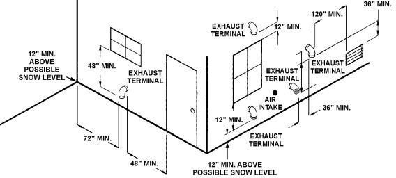
FIGURE 18. VENT TERMINATIONSAND INSTALLATION CLEARANCES
TABLE 6. SINGLE UNIT INSTALLATION, SUGGESTED PIPE SIZE
|
|
|
|
|
|
|
|
Maximum Equivalent Pipe Length |
|
|
|
|
|
|
|
||||
|
|
|
|
|
Natural Gas 1,000 BTU/FT3 |
0.60 Specific Gravity @ 0.5 In. W.C. Pressure Drop |
|
|
|
||||||||||
|
|
|
|
Propane Gas 2,500 BTU/FT3 |
1.53 Specific Gravity @ 0.60 In.W.C. Pressure Drop |
|
|
|
|||||||||||
BTUH |
|
3/4" |
|
|
1" |
1 1/4" |
|
1 1/2" |
|
2" |
|
|
2 1/2" |
||||||
Input |
N |
|
P |
|
N |
|
P |
N |
P |
N |
|
P |
N |
|
P |
|
N |
|
P |
300,000 |
15 |
|
25 |
|
35 |
|
85 |
150 |
380 |
360 |
|
- |
- |
|
- |
|
- |
|
- |
399,900 |
- |
|
15 |
|
25 |
|
60 |
100 |
260 |
250 |
|
- |
- |
|
- |
|
- |
|
- |
500,000 |
- |
|
10 |
|
15 |
|
35 |
65 |
150 |
130 |
|
360 |
500 |
|
- |
|
- |
|
- |
650,000 |
- |
|
- |
|
10 |
|
25 |
45 |
100 |
95 |
|
250 |
340 |
|
- |
|
- |
|
- |
750,000 |
- |
|
- |
|
- |
|
20 |
35 |
80 |
75 |
|
180 |
260 |
|
600 |
|
- |
|
- |
TO TRAP ANY DIRT OR FOREIGN MATERIAL IN THE GAS SUPPLY LINE, A DIRT LEG (SOMETIMES CALLED DRIP LEG) MUST BE INCORPORATED IN THE PIPING. The dirt leg must be readily accessible and not subject to freezing conditions. INSTALL IN ACCORDANCE WITH RECOMMENDATIONS OF SERVING GAS SUPPLIERS. REFER TO NATIONALFUEL GAS CODE,ANSI Z223.1 OR CAN/CSA-B149.1 (CURRENT EDITION).
To prevent damage, care must be taken not to apply too much torque when attaching gas supply pipe to gas valve gas inlet.
Fittings and unions in the gas line must be metal to metal type.
Apply joint compounds (pipe dope) sparingly and only to the male threads of pipe joints. Do not apply compound to the first two threads. Use compounds resistant to the action of liquefied petroleum gases.
THE BOILER MUST BE ISOLATED FROM THE GAS SUPPLY PIPING SYSTEM BY CLOSING ITS MAIN MANUAL GAS SHUTOFF VALVE DURING ANY PRESSURE TESTING OF THE GAS SUPPLY PIPING SYSTEM AT TEST PRESSURES EQUAL TO OR MORE THAN 1/2 PSIG.
PURGING
Gas line purging is required with new piping or systems in which air has entered.
 CAUTION
PURGING SHOULD BE PERFORMED BY PERSONS EXPERIENCED IN THIS TYPE OF GAS SERVICE TOAVOID RISK OF FIRE OR EXPLOSION. PURGE DISCHARGE MUST NOT ENTER CONFINEDAREAS OR SPACES WHERE IGNITION CAN
OCCUR. THE AREA MUST BE WELL VENTILATED AND ALL SOURCES OF IGNITION MUST BE DEACTIVATED OR REMOVED.
BEFORE PLACING THE BOILER IN OPERATION, CHECK FOR GAS LEAKAGE. Use soap and water solution or other material acceptable for the purpose in locating gas leaks. DO NOT USE MATCHES, CANDLES, FLAME OR OTHER SOURCES OF IGNITION FOR THIS PURPOSE.
1.CORRECT GAS
Make sure the gas on which the boiler will operate is the same as that specified on the boiler rating plate. Do not install the boiler if equipped for a different type gas, consult your gas supplier.
2A. SIZING GAS SUPPLY LINE, (for single boiler installations), see Table 6.
2B. SIZING GAS SUPPLY LINE, (for multiple installations of two or more boilers), see Table 7.
Use Table 7, which is taken from ANSI booklet Z223.1, NATIONAL FUEL GAS CODE, or CAN/CSA-B149.1 (current edition) to size iron pipe or equivalent gas supply line. Table 7 is based on a pressure drop of 0.5 inches of water and a specific gravity of 0.60 approximately that of natural gas. (LP gas has an S.G. of about 1.53).
Capacities in cubic feet per hour of 0.60 specific gravity gas for different sizes and lengths of pipe are shown in Table 7. No additional allowance is necessary for an ordinary number of fittings.
Where it is necessary to use more than the average number of pipe fittings (e.g., elbows, tees, and valves in gas supply line), use a pipe size larger than specified to compensate for increased pressure drop.
12
TABLE 7. SUGGESTED PIPE SIZE FOR MULTIPLE GASAPPLIANCES
Nominal |
|
|
Maximum Capacity of Pipe in Cubic Feet of Gas per Hour for Gas Pressures |
|
|
||||||||||
Iron Pipe |
of 14 in. W.C. (0.5 psi) or Less and a Pressure Drop of 0.5 in W.C. based on a 0.60 Specific Gravity Gas |
||||||||||||||
Size in |
|
|
|
|
|
Length of Pipe (Feet) |
|
|
|
|
|
|
|||
Inches |
10 |
20 |
30 |
40 |
50 |
60 |
70 |
80 |
|
90 |
100 |
125 |
150 |
175 |
200 |
1 |
680 |
465 |
375 |
320 |
285 |
260 |
240 |
220 |
|
205 |
195 |
175 |
160 |
145 |
135 |
1 1/4 |
1,400 |
950 |
770 |
660 |
580 |
530 |
490 |
460 |
|
430 |
400 |
360 |
325 |
300 |
280 |
1 1/2 |
2,100 |
1,460 |
1,180 |
990 |
900 |
810 |
750 |
690 |
|
650 |
620 |
550 |
500 |
460 |
430 |
2 |
3,950 |
2,750 |
2,200 |
1,900 |
1,680 |
1,520 |
1,400 |
1,300 |
|
1,220 |
1,150 |
1,020 |
950 |
850 |
800 |
2 1/2 |
6,300 |
4,350 |
3,520 |
3,000 |
2,650 |
2,400 |
2,250 |
2,050 |
|
1,950 |
1,850 |
1,650 |
1,500 |
1,370 |
1,280 |
3 |
11,000 |
7,700 |
6,250 |
5,300 |
4,750 |
4,300 |
3,900 |
3,700 |
|
3,450 |
3,250 |
2,950 |
2,650 |
2,450 |
2,280 |
4 |
23,000 |
15,800 |
12,800 |
10,900 |
9,700 |
8,800 |
8,100 |
7,500 |
|
7,200 |
6,700 |
6,000 |
5,500 |
5,000 |
4,600 |
TABLE 8. MULTIPLIER TABLE
Specific |
|
Specific |
|
Gravity |
Multiplier |
Gravity |
Multiplier |
0.55 |
1.04 |
1.00 |
0.78 |
0.60 (natural) |
1.00 |
1.10 |
0.74 |
0.65 |
0.96 |
1.20 |
0.71 |
0.70 |
0.93 |
1.30 |
0.68 |
0.75 |
0.90 |
1.40 |
0.66 |
0.80 |
0.87 |
1.50 (Propane) |
0.63 |
0.85 |
0.84 |
1.60 |
0.61 |
0.90 |
0.82 |
1.70 |
0.59 |
Applications of the gravity factor converts the figures given in Table 7 to capacities with another gas of different specific gravity. Such application is accomplished by multiplying the capacities given in Table 7 by the multipliers shown in Table 8.
HIGH ALTITUDE INSTALLATIONS
 WARNING
INSTALLATIONS ABOVE 5,000 FEET REQUIRE REPLACEMENT OF THE BURNER ORIFICES IN ACCORDANCE WITH THE NATIONAL FUEL GAS CODE (ANSI/NFPA 54). FAILURE TO REPLACE THE ORIFICES WILL RESULT IN IMPROPER AND INEFFICIENT OPERATION OF THE APPLIANCE, PRODUCING CARBON MONOXIDE GAS IN EXCESS OF SAFE LIMITS, WHICH COULD RESULT IN SERIOUS PERSONAL INJURY OR DEATH.
These Genesis boilers are equipped with prejet orifices which are self-regulating. This makes it unnecessary to replace these prejet orifices for high altitude installations (up to 5,000 feet only. Consult the factory for higher altitudes). These prejet orifices will automatically compensate for higher elevations and adjust the appliance's input rate accordingly, see Table 9.
Some utility companies derate their gas for altitude. You should contact your gas supplier for any specific changes which may be required in your area. Call the local gas utility to verify BTU content of the gas supplied.
Ratings specified by manufacturers for most boilers apply for elevations up to 2000 feet (600 m). For elevations above 2000 feet (600 m) ratings must be reduced by a rate of 4% for each 1000 feet (300 m) above sea level.
Example: A Genesis boiler is rated at 750,000 Btu/hr. input at sea level. At an altitude of 5,000 (1500m), the prejet orifices will decrease the input rate by 20% (= 4% x 5) to a new rating of 600,000 Btu/hr. (= 80% x 750,000 Btu/hr.) The input reduction is achieved by the prejet orifices through self-regulation.
WIRING CONNECTIONS
ALL ELECTRICAL WORK MUST BE INSTALLED IN ACCORDANCE WITH THE CURRENT EDITIONS OF THE NATIONAL ELECTRICAL CODE NFPA 70/CANADIAN ELECTRICAL CODE, CSA22.1AND MUST CONFORM TO LOCAL REGULATIONS.
AN ELECTRICAL GROUND IS REQUIRED TO REDUCE RISK OF ELECTRIC SHOCK OR POSSIBLE ELECTROCUTION. Make the ground connection to the wire provided in the electrical supply junction box on the boiler.
Grounding and all wiring connected to this boiler must conform to the local code authority having jurisdiction or, in the absence of such requirements, with the National Electrical Code, ANSI/NFPA 70 or CSA-C22.1 current edition.
IF ANY OF THE ORIGINAL WIRE, AS SUPPLIED WITH THE APPLIANCE, MUST BE REPLACED, IT MUST BE REPLACED WITH TYPE 105°C WIRE OR ITS EQUIVALENT.
The Genesis Hot Water Supply Boiler must be connected to a single phase dedicated and isolated line source that is:
120 volts, 60 Hertz, and 20 Amps.
The feedback contacts for a system controller (e.g. Honeywell Aquastat) that is attached to the thermostat input, must operate on the provided 24 VAC power.
Refer to the Connection Diagram and to the Schematic Diagram.
TABLE 9: ORIFICE SIZE FOR NATURALAND PROPANE (LP) GASES (U.S.AND CANADIAN INSTALLATIONS) (Drill size unless otherwise indicated.)
Model |
Rating Input BTUH |
Number of Burners |
Natural (3X) |
Propane (3X) |
GB/GW 300 |
300,000 |
6 |
0.091" |
0.048" |
GB/GW 400 |
399,900 |
8 |
0.091" |
0.048" |
GB/GW 500 |
500,000 |
10 |
0.091" |
0.048" |
GB/GW 650 |
650,000 |
13 |
0.091" |
0.048" |
GB/GW 750 |
750,000 |
15 |
0.091" |
0.048" |
13

GENESIS GB/GW 300-750 WIRING DIAGRAM
FIGURE19.
 Loading...