


BTF-80
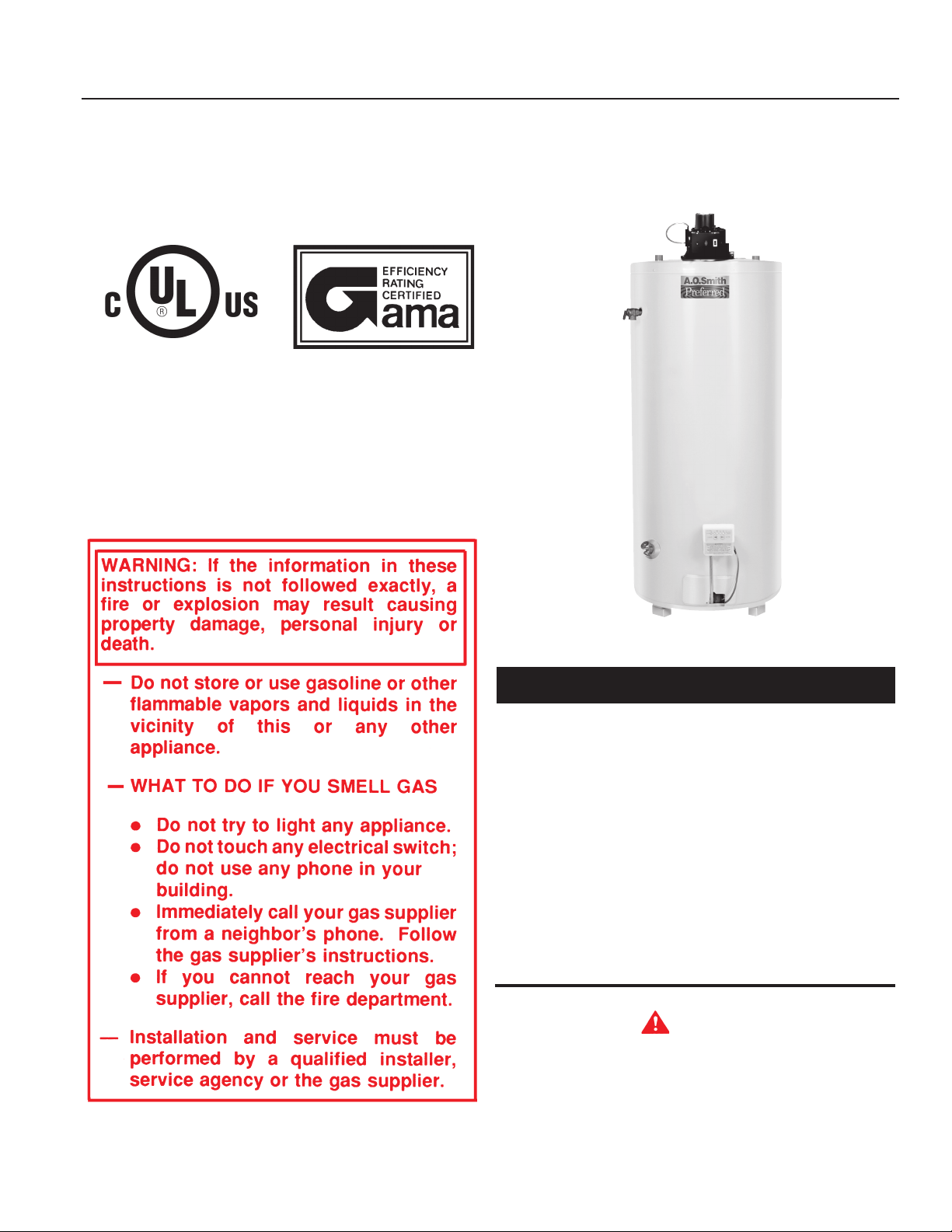
MODEL BTF-80
COMMERCIAL POWER VENT GAS WATER HEATER
with Hot Surface Ignition
Thank you for buying this energy efficient water heater.
We appreciate your condence in our products.
You should thoroughly read this manual before installation and/
or operation of this water heater. Please pay particular attention
to the important safety and operating instructions as well as the
WARNINGS and CAUTIONS.
TABLE OF CONTENTS
PAGE
GET TO KNOW YOUR WATER HEATER 2-3
GENERAL SAFETY INFORMATION 4-5
INSTALLATION 5-14
OPERATION 14-16
MAINTENANCE AND
TROUBLESHOOTING 16-19
TROUBLESHOOTING WITH THE LEDs 20
WARRANTY 24
CAUTION
TE X T P R I NTE D O R O U T L INE D I N R E D C O NTA I N S
INFO RMATI ON REL ATIVE TO YOUR SAFETY. PLEASE
READ THOROUGHLY BEFORE INSTALLING AND USING
THIS APPLIANCE.
KEEP THIS MANUAL IN THE POCKET ON THE HEATER FOR FUTURE REFERENCE
WHENEVER MAINTENANCE ADJUSTMENT OR SERVICE IS REQUIRED.
PRINTED IN U.S.A. 0406 PART NO. 197440-000
1
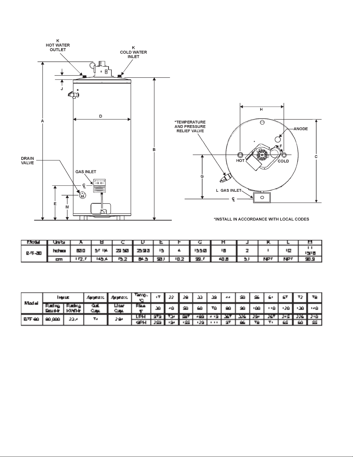
ROUGH-IN-DIMENSIONS
TOP VIEW
RECOVERY CAPACITIES
Recovery capacity based on 80% thermal efciency.
FOREWORD
The design of model BTF-80 complies with the current version
of ANSI Z21.10.3/CSA 4.3 as automatic storage or automatic
circulating tank type water heaters.
Installation diagrams are found in this manual. These diagrams
will serve to provide the installer with a reference for the
materials and method of piping necessary. It is highly essential
that all water and gas piping be installed as shown on the
diagrams.
In addition to these instructions, the equipment shall be installed
in accordance with those installation regulations in force in the
local area where the installation is to be made. These shall be
carefully followed in all cases. Authorities having jurisdiction
should be consulted before installations are made.
The installation must conform to these instructions and the local
code authority having jurisdiction. In the absence of local codes, the
installation must comply with the current editions of the National
Fuel Gas Code, ANSI Z223.1/NFPA 54 and the National Electrical
Code, NFPA 70 or CAN/CSA-B149.1, the Natural Gas and Propane
Installation Code and CSA C22.1, the Canadian Electrical Code.
All documents are available from the Canadian Standards
Association, 8501 East Pleasant Valley Road, Cleveland, OH
44131. NFPA documents are also available from the National Fire
Protection Association, 1 Batterymarch Park, Quincy, MA 02269.
2
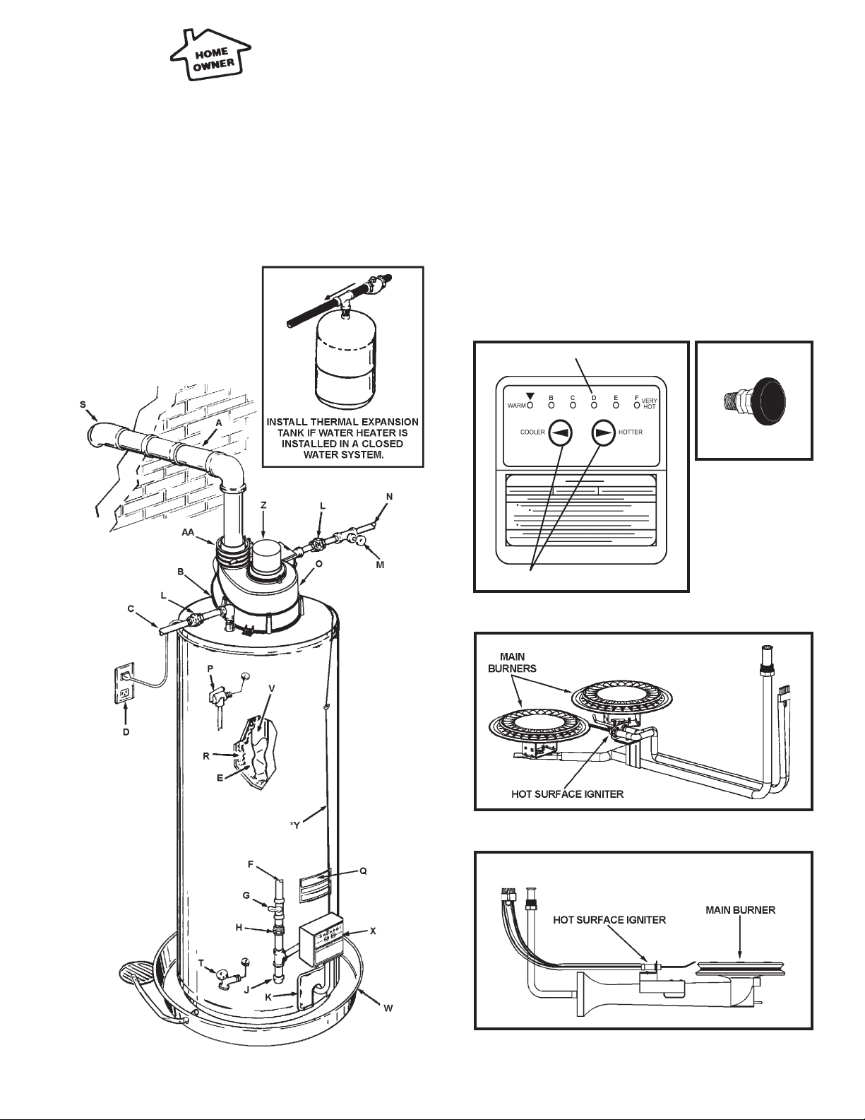
GET TO KNOW YOUR WATER HEATER
REPLACEMENT PARTS AND DELIMING PRODUCTS
Replacement parts and recommended delimer may be ordered
through authorized servicers or distributors. Refer to the Yellow
Pages for where to call or contact the water heater manufacturer
at, 500 Tennessee Waltz Parkway, Ashland City, TN 37015. When
ordering parts, provide complete model and serial numbers (see
rating plate), quantity and name of part desired (as listed in Figure
1). Standard hardware items may be purchased locally.
(A) VENT PIPE
(B) ANODE
(C) HOT WATER OUTLET
(D) OUTLET (120 VAC)
(E) FLUE BAFFLE
(F) GAS SUPPLY
(G) MAIN MANUAL GAS
SHUT OFF VALVE
(H) GROUND JOINT UNION
(J) DIRT LEG
(K) OUTER DOOR
(L) UNION
(M) INLET WATER SHUT
OFF VALVE
(N) COLD WATER INLET
(O) INLET DIP TUBE
(P) TEMPERATURE AND
PRESSURE RELIEF VALVE
(Q) RATING PLATE
(R) INSULATION
(S) VENT TERMINAL
(T) DRAIN VALVE
(U) IGNITER AND MAIN
BURNER
(V) FLUE
(W) DRAIN PAN
(X) CONTROL
(Y) CONTROL HARNESS*
(Z) MOTOR & BLOWER
(AA) CONDENSATE FITTING
*CAUTION HARNESS HAS 115 VAC. IN OPERATION
TEMPERATURE INDICATORS
VACUUM RELIEF
VALVE
*INSTALL PER
LOCAL CODES
TEMPERATURE ADJUSTMENT BUTTONS
(U) NATURAL GAS MAIN BURNER
WITH IGNITER ASSEMBLY
(U) PROPANE GAS MAIN BURNER
WITH IGNITER ASSEMBLY
(SIDE VIEW)
FIGURE 1
3
GENERAL SAFETY INFORMATION
EXTERNAL DAMAGE
Do not operate the water heater until it has been fully checked out
by a qualied technician, if the water heater:
• Has been exposed to re or damage.
• Displays evidence of sooting.
• Produces steam or unusually hot water.
If the water heater has been subject to ooding it must be
replaced.
CHEMICAL VAPOR CORROSION
WARNING
CORROSION OF THE FLUEWAYS AND VENT SYSTEM MAY
OCCUR IF AIR FOR COMBUSTION CONTAINS CERTAIN
CHEMICAL VAPORS. SUCH CORROSION MAY RESULT IN
FAILURE AND RISK OF ASPHYXIATION.
Spray can propellants, cleaning solvents, refrigerator and air
conditioning refrigerants, swimming pool chemicals, calcium and
sodium chloride (water softener salt), waxes, and process chemicals
are typical compounds which are potentially corrosive.
Do not store products of this sort near the heater. Also, air
which is brought in contact with the heater should not contain
any of these chemicals. If necessary, uncontaminated air
should be obtained from remote or outside sources. The
limited warranty is voided when failure of water heater is due
to a corrosive atmosphere. (See limited warranty for complete
terms and conditions).
LP gas must be used with great caution. It is highly explosive
and heavier than air. It collects rst in the low areas making its
odor difcult to detect at nose level. If LP gas is present or even
suspected, do not attempt to nd the cause yourself. Go to a
neighbor's house, leaving your doors open to ventilate the house,
then call your gas supplier or service agent. Keep area clear until
a service call has been made.
At times you may not be able to smell an LP gas leak. One cause
is odor fade, which is a loss of the chemical odorant that gives
LP gas its distinctive smell. Another cause can be your physical
condition, such as having a cold or a diminishing sense of smell
with age. For these reasons, the use of a propane gas detector
is recommended.
IF YOU EXPERIENCE AN OUT-OF-GAS SITUATION, DO
NOT TRY TO RELIGHT APPLIANCES YOURSELF. Ask your
LP delivery person to relight pilots for you. Only trained LP
professionals should conduct the required safety checks in
accordance with industry standards.
EXTENDED NON-USE PERIODS
WARNING
HYDROGEN GAS CAN BE PRODUCED IN A HOT WATER
SYSTEM SERVED BY THIS HEATER THAT HAS NOT BEEN
USED FOR A LONG PERIOD OF TIME (GENERALLY TWO
WEEKS OR MORE). HYDROGEN GAS IS EXTREMELY
FLAMMABLE. To reduce the risk of injury under these conditions,
it is recommended that the hot water faucet be opened for several
minutes at the kitchen sink before using any electrical appliance
connected to the hot water system. If hydrogen is present, there
will probably be an unusual sound such as air escaping through
the pipe as the water begins to ow. THERE SHOULD BE NO
SMOKING OR OPEN FLAME NEAR THE FAUCET AT THE TIME
IT IS OPEN.
IMPROPER COMBUSTION
WARNING
ATTIC AN D/O R EX HAU ST FANS OPERATIN G ON THE
PREMISES WITH A WATER HEATER CAN RESULT IN CARBON
MONOXIDE POISONING AND DEATH.
OPERATION OF THESE FANS CAN PRODUCE A NEGATIVE
DRAFT IN THE AREA OF THE WATER HEATER PREVENTING
THE PRODUCTS OF COMBUSTION FROM EXHAUSTING
THROUGH THE VENT PIPE.
The venting of the water heater should be inspected by a qualied
service technician at the time of installation and periodically
thereafter to ensure a down-draft condition does not exist.
DO NOT OBSTRUCT THE FLOW OF COMBUSTION AND
VENTILATING AIR. ADEQUATE AIR FOR COMBUSTION AND
VENTILATION MUST BE PROVIDED FOR SAFE OPERATION.
LIQUID PETROLEUM MODELS
WARNING
Water heaters for propane or liqueed petroleum gas (LPG) are
different from natural gas models. A natural gas heater will not
function safely on LP gas and no attempt should be made to
convert a heater from natural gas to LP gas.
INSULATION BLANKETS
Insulation blankets available to the general public for external
use on gas water heaters are not necessary with this product.
The purpose of an insulation blanket is to reduce the standby
heat loss encountered with storage tank heaters. Your water
heater meets and exceeds the Energy Policy Act with respect to
insulation and standby loss requirements, making an insulation
blanket unnecessary.
WARNING
Should you choose to apply an insulation blanket to this
heater, you should follow these instructions (See Figure 1 for
identication of components mentioned below). Failure to follow
these instructions can restrict the air ow required for proper
combustion, potentially resulting in re, asphyxiation, serious
personal injury or death.
• Do not cover the gas valve or temperature & pressure relief
valve.
• Do not allow insulation to come within 2" (5.1 cm) of the dilution
air inlet on the blower, to prevent blockage of the dilution air.
• Do not allow insulation to come within 2" (5.1 cm) of the oor
to prevent blockage of combustion air ow to the burner.
4
• Do not cover the instruction manual. Keep it on the side of the
water heater or nearby for future reference.
• Do obtain new warning and instruction labels for placement
on the blanket directly over the existing labels.
• Do inspect the insulation blanket frequently to make certain it
does not sag, thereby obstructing combustion air ow.
sides and rear, 5.5" (14 cm) from the front and 12" (30 cm) from
the top. (Standard clearance.) If clearances stated on the heater
differ from standard clearances, install water heater according to
clearances stated on heater.
A minimum clearance of 4" (10 cm) must be allowed for access
to replaceable parts such as the thermostats, drain valve and
relief valve. A top clearance of 24" (61 cm) should be allowed for
blower assembly service.
INSTALLATION
REQUIRED ABILITY
INSTALLATION OR SERVICE OF THIS WATER HEATER REQUIRES
ABILITY EQUIVALENT TO THAT OF A LICENSED TRADESMAN IN
THE FIELD INVOLVED. PLUMBING, ELECTRICAL, AIR SUPPLY,
VENTING AND GAS SUPPLY ARE REQUIRED.
GENERAL
MAKE SURE that the gas supply where this water heater will be
installed is the same as that stated on its model and rating plate.
The installation must conform with these instructions and the local
code authority having jurisdiction. In the absence of local codes,
installations shall comply with the National Fuel Gas Code, ANSI
Z223.1/NFPA 54 and the National Electrical Code, NFPA 70 or
CAN/CSA-B149.1, the Natural Gas and Propane Installation Code
and CSA C22.1, the Canadian Electrical Code. All documents are
available from the Canadian Standards Association, 8501 East
Pleasant Valley Road, Cleveland, OH 44131. NFPA documents
are also available from the National Fire Protection Association,
1 Batterymarch Park, Quincy, MA 02269.
GROUNDING
The water heater when installed must be grounded in accordance with
the local codes, or in the absence of local codes: The National Electrical
Code, NFPA 70 or the Canadian Electrical Code CSA C221.1.
HIGH ALTITUDE INSTALLATION
INSTALLATIONS ABO VE 7700 FT. (2,347 m) REQUIRE
REPLACEMENT OF THE BURNER ORIFICE IN ACCORDANCE
WITH NATURAL GAS AND PROPANE INSTALLATION CODE CAN/
CSA B149.1. FAILURE TO REPLACE THE ORIFICE COULD RESULT
IN IMPROPER AND INEFFICIENT OPERATION OF THE APPLIANCE,
PRODUCING CARBON MONOXIDE GAS IN EXCESS OF SAFE
LIMITS, WHICH COULD RESULT IN SERIOUS PERSONAL INJURY
OR DEATH. CONTACT YOUR GAS SUPPLIER FOR ANY SPECIFIC
CHANGES WHICH MAY BE REQUIRED IN YOUR AREA.
SOME MODEL S ARE BUILT SPECI FICALLY FOR HIGH
ALTITUDE SERVICE.
PLEASE CHECK THE RATING PLATE BEFORE MAKING CHANGES.
CAUTION
LOCATION OF HEATER
When installing the heater, consideration must be given to proper
location. Location selected should be as close to the outside wall
to be used for terminations as practicable with adequate air supply
and as centralized with the water piping system as possible.
Adequate clearance for servicing this appliance should be
considered before installation, such as changing the anodes, etc.
Minimum clearances for proper operation are given above.
In cold climates provide protection against freeze-up.
THE HEATER SHOULD BE LOCATED IN AN AREA WHERE
LEAKAGE OF THE TANK OR CONNECTIONS WILL NOT
RESULT IN DAMAGE TO THE AREA ADJACENT TO THE
HEATER OR TO LOWER FLOORS OF THE STRUCTURE.
When such locations cannot be avoided, a suitable drain pan
should be installed under the heater, see gure 1. The pan
must not restrict combustion air ow. Such pans should have a
minimum length and width of at least 2" (5.1 cm) greater than the
diameter of the heater and should be piped to an adequate drain.
Drain pans suitable for these heaters are available from the water
heater manufacturer at, 500 Tennessee Waltz Parkway, Ashland
City, TN 37015.
Installation of the water heater must be accomplished in such a
manner that if the tank or any of the connections should leak, the
ow will not cause damage to the structure. For this reason, it is
not advisable to install the water heater in an attic or upper oor.
When such locations can not be avoided, a suitable drain pan
should be installed under the water heater.
Water heater life depends upon water quality, water pressure
and the environment in which the water heater is installed. Water
heaters are sometimes installed in locations where leakage may
result in property damage, even with the use of a drain pan piped
to a drain. However, unanticipated damage can be reduced or
prevented by a leak detector or water shut-off device used in
conjunction with a piped drain pan.
These devices are available from some plumbing supply
wholesalers and retailers, and detect and react to leakage in
various ways:
• Sensors mounted in the drain pan that trigger an alarm or turn
off the incoming water to the water heater when leakage is
detected.
• Sensors mounted in the drain pan that turn off the water supply
to the entire home when water is detected in the drain pan.
• Water supply shut-off devices that activate based on the water
pressure differential between the cold water and hot water pipes
connected to the water heater.
• Devices that will turn off the gas supply to a gas water heater
while at the same time shutting off its water supply.
DO NOT INSTALL THIS WATER HEATER DIRECTLY ON A
CARPETED FLOOR. A FIRE HAZARD MAY RESULT. Instead the
water heater must be placed on a metal or wood panel extending
beyond the full width and depth by at least 3 inches (7.6 cm) in any
direction. If the heater is installed in a carpeted alcove or closet,
the entire oor shall be covered by the panel.
WARNING
WARNING
The heater is design certied by the Underwriters Laboratories Inc.
for installation on combustible ooring in a closet having minimum
clearances from combustible material of: 0" (0 cm) clearance from
AIR REQUIREMENTS
In calculating the free area of a vent opening, the blocking effect
5
of screens, louvers and grills should be considered. Screens shall
not be of a mesh smaller than 1/4" (6.3 mm) square. If the free
area is not known, the National Fuel Gas Code, ANSI Z223.1/NFPA
54 or the Natural Gas and Propane Installation Code CAN/CSA
B149.1 recommends using gures of 20-25 percent free area for
wood louvers or 60-75 percent for metal grills or louvers.
WATER CONNECTIONS
Refer to gure 1 for typical installation. A suitable pipe thread
sealant must be used to prevent leakage.\
WATER (POTABLE) HEATING AND SPACE HEATING
UNCONFINED SPACE
In buildings of conventional frame, brick or stone construction,
unconned spaces may provide adequate air for combustion,
ventilation, and dilution air for power venter.
If the unconned space is within a building of tight construction
(building using the following construction: weather stripping,
heavy insulation, caulking, vapor barrier, etc.), air for combustion,
ventilation, and venter dilution must be obtained from outdoors. The
installation instructions for conned spaces must be followed.
CONFINED SPACE
When drawing combustion and dilution air from inside a conventionally
constructed building to a conned space, such a space shall be provided
with two permanent openings. ONE WITHIN 12" (30 cm) OF THE
ENCLOSURE TOP AND ONE WITHIN 12" (30 cm) OF THE ENCLOSURE
BOTTOM. Each opening shall have a free area of one square inch (6.5 cm²)
per 1000 Btuh (292.8 W) of the total input of all appliances in the enclosure,
but not less than 100 square inches (645 cm²).
If the conned space is within a building of tight construction, air for
combustion, ventilation and power venter dilution must be obtained
from outdoors. When directly communicating with the outdoors or
communicating through vertical ducts, two permanent openings,
located in the above manner, shall be provided. Each opening shall
have a free area of not less than one square inch (6.5 cm²) per 4000
Btuh (1,171 W) of the total input of all appliances in the enclosure.
If horizontal ducts are used, each opening shall have a free area of
not less than one square inch (6.5 cm²) per 2000 Btuh (585.6 W)
of the total input of all appliances in the enclosure.
1. All piping components connected to this unit for space heating
applications shall be suitable for use with potable water.
2. Toxic chemicals, such as those used for boiler treatment, shall
NEVER be introduced into this system.
3. This unit may NEVER be connected to any existing heating
system or component(s) previously used with a non-potable
water heating appliance.
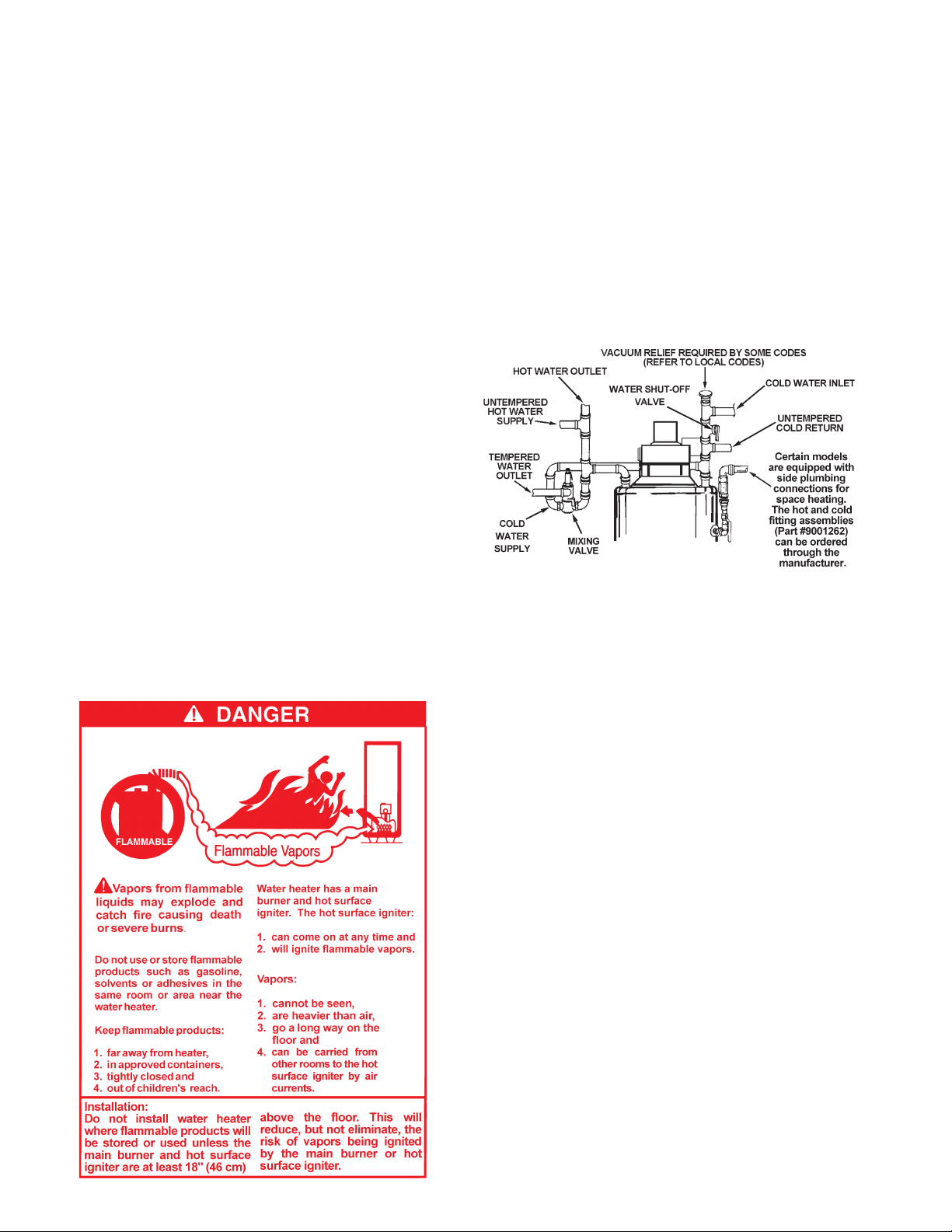
4. When the system requires water for spa ce heating at
temperatures higher than required for domestic water purposes,
a tempering valve must be installed. Please refer to Figure 2
for suggested piping arrangement.
FIGURE 2
CLOSED WATER SYSTEM
A closed system will exist if a back-ow preventer (check valve),
pressure reducing valve, or other similar device is installed in
the cold water line between the water heater and the street main
(or well). Excessive pressure may develop due to the thermal
expansion of heated water causing premature tank failure or
intermittent relief valve operation. This type of failure is not
covered by the limited warranty. An expansion tank may be
necessary in the cold water supply to alleviate this situation, see
Figure 1. Contact the local plumbing authority.
If the temperature and pressure relief valve on the appliance
discharges periodically, this may be due to thermal expansion in
a closed water supply system. Contact the water supplier or local
plumbing inspector on how to correct situation. DO NOT PLUG
THE TEMPERATURE AND PRESSURE RELIEF VALVE.
GAS CONNECTIONS
The minimum gas supply pressure for input adjustment is 5.0" (12.7
cm) W.C. for natural gas (11.0" (27.9 cm) W.C. for propane).
THE HEATER IS NOT INTENDED FOR OPERATION AT HIGHER
THAN 14" (35.6 cm) WATER COLUMN SUPPLY PRESSURE.
EXPOSURE TO HIGHER GAS SUPPLY PRESSURE MAY
CAUSE DAMAGE TO THE CONTROL WHICH COULD RESULT
IN FIRE OR EXPLOSION. If overpressure has occurred such as
through improper testing of gas lines or emergency malfunction of
the supply system, the control must be checked for safe operation.
Make sure that the outside vents on the supply regulators and
the safety vent valves are protected against blockage. These are
parts of the gas supply system not the heater. Vent blockage may
occur during ice storms.
IT IS IMPORTANT TO GUARD AGAINST CONTROL FOULING
FROM CONTAMINANTS IN THE GAS WAYS. SUCH FOULING
6
WARNING
VENT HOOD(S) MAY BE EXTREMELY HOT DURING OPERATION.
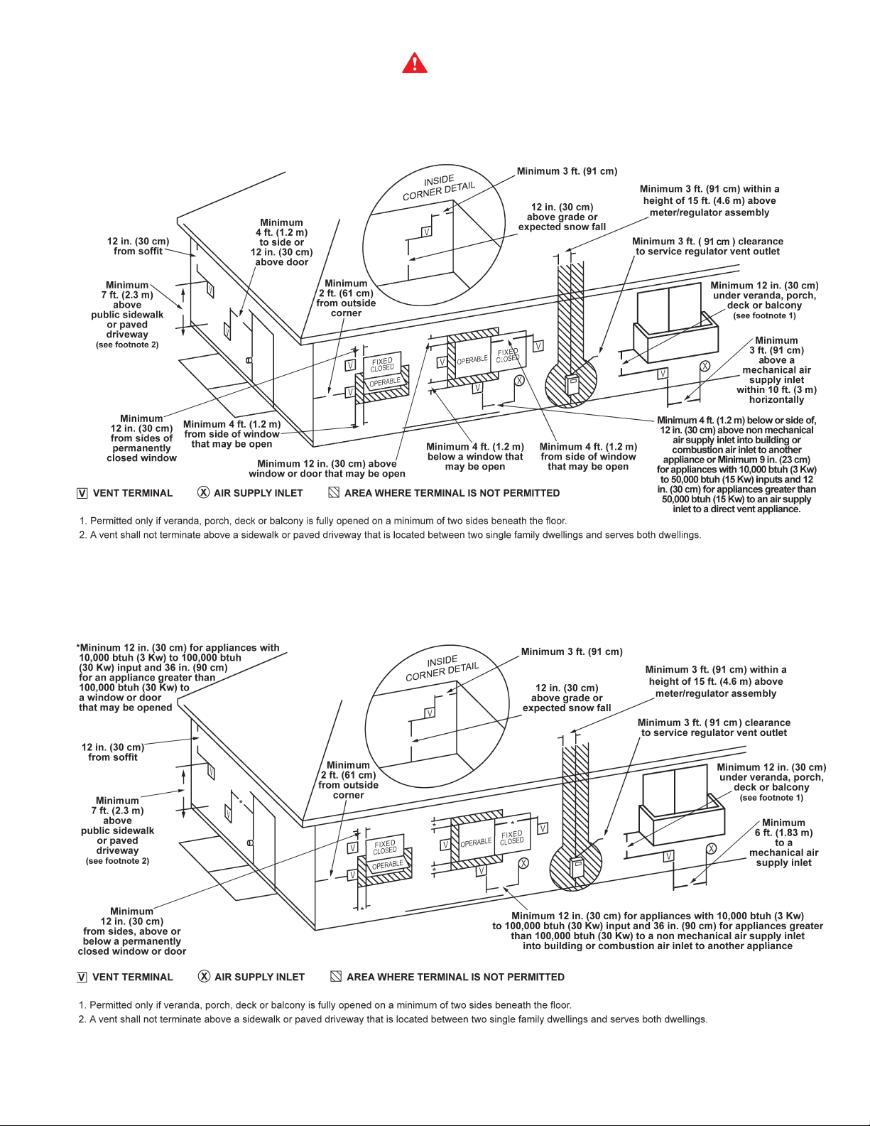
U.S. HORIZONTAL VENT CLEARANCES
CANADIAN HORIZONTAL VENT CLEARANCES
FIGURE 3
7
MAY CAUSE IMPROPER OPERATION, FIRE OR EXPLOSION.
All piping must comply with local codes and ordinances or with the
National Fuel Gas Code NFPA 70 or the Natural Gas and Propane
Installation Code CAN/CSA B149.1, whichever applies.
REFER TO FIGURE 1 FOR CONNECTION DETAILS. BEFORE
ATTACHING THE GAS LINE BE SURE THAT ALL GAS PIPE IS
CLEAN ON THE INSIDE.
TO TRAP ANY DIRT OR FOREIGN MATERIAL IN THE GAS
SUPPLY LINE, A DIRT LEG (SOMETIMES CALLED DRIP LEG)
MUST BE INCORPORATED IN THE PIPING, FIGURE. 1. The
dirt leg must be readily accessible. Install in accordance with
recommendations of serving gas supplier. Refer to the National
Fuel Gas Code, ANSI Z223.1/NFPA 54 or the Natural Gas and
Propane Installation Code CAN/CSA B149.1.
To prevent damage, care must be taken not to apply too much
torque when attaching gas supply pipe to thermostat gas inlet. The
thermostat inlet has a pad for use with a backup wrench.
Apply joint compounds (pipe dope) sparingly and only to the
male threads of pipe joints. Do not apply compound to the rst
two threads. Use compounds resistant to the action of liqueed
petroleum gases. Do not use teon tape on thermostat ttings.
CONNECTION OF GAS PIPE
1. When connecting gas pipe to unit, apply wrench to ange only.
Note: Do not use wrench on gas valve or gas valve bracket.
2. PERFORM THE GAS LEAK TEST ANY TIME WORK IS DONE
ON A GAS SYSTEM TO AVOID THE POSSIBILITY OF FIRE
OR EXPLOSION WITH PROPERTY DAMAGE, PERSONAL
INJURY, OR LOSS OF LIFE.
The Gas Leak Test is performed as follows: Paint pipe
connections upstream of gas control with a rich soap and water
solution to test for leaks before operating main burner. Bubbles
indicate gas leak. To stop leak, tighten pipe connections.
After piping connections are checked, turn on main burner.
(See Lighting and Operating Installations in this manual or on
water heater.) With main burner in operation, paint pipe joints
(including anges) and control inlet and outlet with rich soap
and water solution. Bubbles indicate gas leak. To stop leak,
tighten ange screws, joints and pipe connections. Replace
part if leak can't be stopped.
DISCONNECT THE APPLIANCE AND ITS INDIVIDUAL SHUT
OFF VALVE FROM THE GAS SUPPLY PIPING SYSTEM
DURING ANY SUPPLY PRESSURE TESTING EXCEEDING
1/2 PSI (3.5 kPa). GAS SUPPLY LINE MUST BE CAPPED
WHEN DISCONNECTED FROM THE HEATER. FOR TEST
PRESSURES AT 1/2 PSI (3.5 kPa) OR LESS, THE APPLIANCE
NEED NOT BE DISCONNECTED, BUT MUST BE ISOLATED
FROM THE SUPPLY PRESSURE TEST BY CLOSING THE MAIN
MANUAL GAS VALVE.
NOT USE MATCHES CANDLES, FLAME OR OTHER SOURCES
OF IGNITION TO LOCATE GAS LEAKS.
RELIEF VALVE
A NEW TEMPERATURE AND PRESSURE RELIEF VALVE
COMPLYING WITH THE STANDARD FOR RELIEF VALVES
AND AUTOMATIC GAS SHUT OFF DEVICES FOR HOT WATER
SUPPLY SYSTEMS, ANSI Z21.22-CSA 4.4 MUST BE INSTALLED
IN THE HEATER IN THE MARKED OPENING PROVIDED. THE
VALVE MUST BE OF A SIZE (INPUT RATING) THAT WILL BE
ADEQUATE FOR YOUR SIZE HEATER.
Check the metal tag on the relief valve and compare it to the heater’s
rating plate. The pressure rating of relief valve must not exceed the
working pressure shown on the rating plate of the heater. In addition
the hourly Btu rated temperature steam discharge capacity of the relief
valve shall not be less than the input rating of the heater. NO VALVE
IS TO BE PLACED BETWEEN THE RELIEF VALVE AND TANK. DO
NOT PLUG THE RELIEF VALVE.
The drain line connected to this valve must not contain a reducing
coupling or other restriction and must terminate near a suitable
drain to prevent water damage during valve operation. The
discharge line shall be installed in a manner to allow complete
drainage of both the valve and line. DO NOT THREAD, PLUG
OR CAP THE END OF THE DRAIN LINE.
VENTING
WARNING
NEVER OPERATE THE HEATER UNLESS IT IS VENTED TO
THE OUTDOORS AND HAS ADEQUATE AIR SUPPLY TO AVOID
RISKS OF IMPROPER OPERATION, FIRE, EXPLOSION OR
ASPHYXIATION.
VENT PIPE TERMINATION
The rst step is to determine where the vent pipe will terminate.
See Figures 3, 8 and 9. The vent may terminate through the roof as
shown in Figure 9 or through a sidewall as shown in Figure 8.
IMPORTANT
The vent system must terminate so that proper clearances are
maintained as cited in local codes or the latest edition of the
National Fuel Gas Code, ANSI Z223.1/NFPA 54 or the Natural
Gas and Propane Installation Code CAN/CSA-B149.1.
For your convenience instructions on proper installation through
a sidewall are provided in Figure 3.
The manufacturer also recommends that the vent system
termination not be installed closer than 3 feet (91 cm) from an
inside corner of an L shaped structure and not be less than 1 foot
(30 cm) above grade. The vent shall terminate a minimum of 12"
(30 cm) above expected snowfall level to prevent blockage of
vent termination.
Plan the vent system layout so that proper clearances are
maintained from plumbing and wiring.
BEFORE PLACING THE HEATER IN OPERATION, CHECK
FOR GAS LEAKAGE. USE SOAP AND WATER SOLUTION OR
OTHER MATERIAL ACCEPTABLE FOR THIS PURPOSE. DO
Vent pipes serving power vented appliances are classied by
building codes as "vent connectors". Required clearances from
combustible materials must be provided in accordance with
information in this manual under LOCATION OF HEATER and
INSTALLATION OF VENT SYSTEM, and with the National Fuel
8
 Loading...