


FPTU50

April 2015
100264133
Hybrid Electric
Heat Pump Water Heater
Installa on Instruc ons and
Use & Care Guide
Keep this manual in the pocket on heater for future reference whenever maintenance, adjustment or service is required.
Retain your original receipt as proof of purchase.
LOW LEAD
C
O
NTENT
DO NOT RETURN THIS UNIT TO THE STORE
Read this manual and the labels on the water heater before you install,
operate, or service it. If you have diffi culty following the direc ons, or
aren’t sure you can safely and properly do any of this work yourself:
• Call our Technical Assistance Hotline at 1-800-527-1953 . We can help you with
installation, operations, troubleshooting, or maintenance. Before you call, write
down the model and serial number from the water heater’s data plate.
Incorrect installa on, opera on, or service can damage the water heater, your house
and other property, and present risks including fi re, scalding, electric shock, and
explosion, causing serious injury or death.
Table of Contents Page
IMPORTANT SAFETY INFORMATION ................................. 3
GETTING STARTED ............................................................6
INSTALLATION ................................................................... 7
DIAGNOSTIC CODES ........................................................ 20
TROUBLESHOOTING CHART ...........................................22
MAINTENANCE ............................................................... 25
REPAIR PARTS ILLUSTRATION ..........................................30
NOTES ............................................................................. 31

COMPLETED INSTALLATION TYPICAL
xxxxx
xxxxx
xxxxx
xxxxx
Thermal Expansion Tank
Shut-off Valve
(Cold)
Primary Condensate
Drain (3/4” PVC)
Drain LineSuitable Drain Pan
Discharge Pipe
(Do Not Cap or Plug)
Temperature and
Pressure Relief Valve
Drain
Cold
(Inlet)
Hot
(Outlet)
Shut-off Valve
(Hot)
Air Filter
User Interface
Module (UIM)
Upper Element
and ECO
Condensate Drain
Access Cover
(See Figure 15, p.11)
Connectivity Port
Drain Valve
Lower Element
2 • Residen al Hybrid Electric Heat Pump Water Heater Use and Care Guide

SAFETY
Residen al Hybrid Electric Heat Pump Water Heater Use and Care Guide • 3
IMPORTANT SAFETY INFORMATION
Important informa on to keep
Fill out this sec on and keep this
manual in the pocket of the water
heater for reference.
Date Purchased:
Model number:
Serial number:
Maintenance performed:* Date:
This is the safety alert symbol. It is used to alert you to
poten al physical injury hazards. Obey all safety mes-
sages that follow this symbol to avoid possible property
damage, serious injury or death. Do not remove any
permanent instruc ons, labels, or the data plate from either the outside of
the water heater or on the inside of the access panels. Keep this manual
near the water heater.
DANGER
Read and follow all safety messages and instruc ons in
this manual.
DANGER indicates hazardous
situa on that, if not avoided, will
result in death or serious injury.
WARNING
WARNING indicates a hazardous
situa on that, if not avoided, could
result in death or serious injury.
CAUTION
CAUTION indicates a hazardous
situa on that, if not avoided, could
result in minor or moderate injury.
NOTICE
NOTICE indicates prac ces not
related to physical injury.
*Drain and fl ush tank, clean air fi lter,
clean condensate pan, and remove and
inspect anode rod a er fi rst six months
of opera on and at least annually
therea er. Operate the Temperature
and Pressure Relief Valve (T&P) annu-
ally and inspect T&P valve every 2-4
years (see the label on the T&P valve for
maintenance schedule). See the Main-
tenance sec on for more informa on
about maintaining this water heater.
The California Safe Drinking Water and Toxic Enforcement Act requires the
Governor of California to publish a list of substances known to the State of
California to cause cancer, birth defects, or other reproductive harm, and
requires businesses to warn of potential exposure to such substances.
WARNING! This product contains one or more chemicals known to the
State of California to cause cancer, birth defects, or other reproduc ve harm.
This appliance can cause low-level exposure to some of the substances
included in the Act.

4 • Residen al Hybrid Electric Heat Pump Water Heater Use and Care Guide
IMPORTANT SAFETY INFORMATION
T
o reduce the risk of property
damage, serious injury or death,
read and follow the precau ons below,
all labels on the water heater, and
the safety messages and instruc ons
throughout this manual.
RISKS DURING INSTALLATION
AND MAINTENANCE
Electric Shock Risk
Contact with the electrical
parts in the junction box,
behind the access doors
and inside the top shroud can result in
severe injury or death from electrical
shock:
• Disconnect power by opening the
circuit breaker or removing the
fuses before installing or servicing.
• Use a non-contact circuit tester to
confirm that power is off before
working on or near any electrical
parts.
• Replace the junction box cover and
access doors after servicing.
Lifting Risk
WARNING! The
water heater is
heavy. Follow these
precau ons to
reduce the risk of property damage,
injuries from li ing or impact injuries
from dropping the water heater.
• Use at least two people to lift the
water heater.
• Be sure you both have a good grip
before lifting.
• Unit is top heavy, u se an appli-
ance dolly (with strap) to move the
water heater.
RISKS DURING OPERATION
Scalding Risk
This water heater
can make water hot
enough to cause
severe burns instantly, resulting in
severe injury or death.
• Feel water before bathing or s how-
ering
• To reduce the risk of scalding,
install Thermostatic Mixing Valves
(temperature limiting valves) at
each point-of-use. These valves
automatically mix hot and cold
water to limit the temperature at
the tap. Mixing valves are available
from your local plumbing supplier .
Follow manufacturer’s instructions
for installation and adjustment of
the valves.
• The User Interface Module (UIM)
on this water heater have been fac-
tory set to approximately 120°F to
reduce the risk of scalding. Higher
temperatures increase the risk of
scalding, but even at 120°F, hot
water can scald. If you choose a
higher temperature, Thermostatic
Mixing Valves located at each point-
of-use are particularly important to
help avoid scalding.
Temperature Time to Produce a
Serious Burn
120°F (49°C) More than 5 minutes
125°F (52°C) 1½ to 2 minutes
130°F (54°C) About 30 seconds
135°F (57°C) About 10 seconds
140°F (60°C) Less than 5 seconds
145°F (63°C) Less than 3 seconds
150°F (66°C) About 1½ seconds
155°F (68°C) About 1 second
For informa on about changing the
factory thermostat se ng(s), refer to
the “Adjus ng Temperature” sec on in
this manual (“Step 13” on page 16).
Even if you set the water heater
thermostat(s) to a low se ng, higher
temperatures may occur in certain
circumstances:
• In some cases, repeated small
draws of water can cause the
hot and cold water in the tank to
“stack” in layers. If this happens,
the water can be as much as thirty
degrees hotter than the thermo-
stat setting. This temperature varia-
tion is the result of your usage pat-
tern and is not a malfunction.
• Water temperature will be hot-
ter if someone adjusted the
thermostat(s) to a higher setting.
• Problems with the thermostat(s),
or other malfunctions may result in
higher than expected water tem-
peratures.
• If the water heater is in a hot envi-
ronment, the water in the tank can
become as hot as the surrounding
air, regardless of the thermostat
setting.
• If the water supplied to the water
heater is pre-heated (for example,
by a solar system) the temperature
in the tank may be higher than the
water heater’s thermostat setting.
To reduce the risk of unusually hot
water reaching the fi xtures in the
house, install Thermosta c Mixing
Valves at each point-of-use.
If anyone in your home is at par cular
risk of scalding (for example, the el-
derly, children, or people with disabili-
es) or if there is a local code or state
law requiring a certain water tempera-
ture at the hot water tap, then these
precau ons are par cularly important.
SAFETY
Residen al Hybrid Electric Heat Pump Water Heater Use and Care Guide • 5
According to a na onal standard
American Society of Sanitary Engineer-
ing (ASSE 1070) and most local plumbing
codes, the water heater’s thermostat
should not be used as the sole means to
regulate water temperature and avoid
scalds.
Properly adjusted Thermosta c Mixing
Valves installed at each point-of-use al-
low you to set the tank temperature to
a higher se ng without increasing risk
of scalds. A higher temperature se ng
allows the tank to provide much more
hot water and can help provide proper
water temperatures for appliances such
as dishwashers and washing machines.
Higher tank temperatures (140°F)
also kill bacteria that cause a condi-
on known as “smelly water” and can
reduce the levels of bacteria that cause
water-borne diseases.
Water Contamination Risk
Do not use chemicals that could con-
taminate the potable water supply. Do
not use piping that has been treated
with chromates, boiler seal, or other
chemicals.
Fire Risk
To reduce the risk of a
fire that could destroy
your home and serious-
ly injure or kill people:
• D o not store things that can burn
easily such as paper or clothes next
to the water heater.
• Be sure the junction box cover and
the access door covers are in place.
These covers keep debris from
entering and potentially being ignit-
ed, and help keep any internal fires
from spreading.
• Keep the water heater from becom-
ing wet. Immediately shut the water
heater off and have it inspected by a
qualified person if you find that the
wiring, thermostat(s) or surround-
ing insulation have been exposed to
water in any way (e.g., leaks from
plumbing, leaks from the water
heater itself can damage property
and could cause a fire risk). If the
water heater is subjected to flood
conditions or the thermostat(s) have
been submerged in water, the entire
water heater must be replaced.
• Make electrical connections prop-
erly, according to the instructions
on page 15. Use 10 gauge solid
copper wire. Use a UL listed or CSA
approved strain relief. Connect
ground wire to green ground screw.
Explosion Risk
High temperatures and
pressures in the water
heater tank can cause an
explosion resulting in property
damage, serious injury or death. A
new Temperature and Pressure (T&P)
Relief Valve is included with your water
heater to reduce risk of explosion by
discharging hot water. Additional
temperature and pressure protective
equipment may be required by local
codes.
A nationally recognized testing labora-
tory maintains periodic inspection of
the valve production process and certi-
fies that it meets the requirements
for Relief Valves for Hot Water Supply
Systems, ANSI Z21.22. The T&P Relief
Valve’s relief pressure must not exceed
the working pressure rating of the wa-
ter heater as stated on the rating plate.
Maintain the T&P Relief Valve properly.
Follow the maintenance instructions
provided by the manufacturer of the
T&P Relief Valve (label attached to T&P
Relief Valve) and the procedure on
page 31.
An explosion could occur if the T&P
Relief Valve or discharge pipe is
blocked. Do not cap or plug the T&P
Relief Valve or discharge pipe.
Fire and Explosion Risk if Hot Water is
Not Used for Two Weeks or More
C AUTION! Hydrogen gas builds up in
a hot water system when it is not used
for a long period (two weeks or more).
Hydrogen gas is extremely fl ammable.
If the hot water system has not been
used for two weeks or more, open a
hot water faucet for several minutes at
the kitchen sink before using any elec-
trical appliances connected to the hot
water system. Do not smoke or have
an open fl ame or other igni on source
near the faucet while it is open.
SAFETY
IMPORTANT SAFETY INFORMATION

6 • Residen al Hybrid Electric Heat Pump Water Heater Use and Care Guide
GETTING STARTED
Figure 1 - Flexible connectors use compres-
sion fittings and do not require soldering.
Figure 2 - Use a non-contact circuit tester
to insure that the power is off before you
work on a circuit.
Figure 3 - Install a Pressure Reducing Valve
set to 50 to 60 PSI.
Figure 4 - Condensate overflow flexible
tubing.
3/4” ID
3/4” OD
3/4” OD
Elbow
Pipe
To Main
Drain Connection
Figure 5 - Main Drain Connection piping.
1
Review all of the instruc ons
before you begin work.
Improper installa on can
damage the water heater, your home
and other property, and can present
risks of serious injury or death.
2
Check with your local and
state authori es for any local
or state codes that apply to
your area. In the absence of local and
state codes, follow Na onal Fire
Protec on Associa on (NFPA-70) and
the current edi ons of the Na onal
Electric Code (NEC) and the Interna-
onal Plumbing Code (IPC). The
instruc ons in this manual comply with
na onal codes, but the installer is
responsible for complying with local
codes.
Massachuse s code requires this wa-
ter heater to be installed in accordance
with Massachuse s 248-CMR 2.00 and
248-CMR 5.00: State Plumbing Code.
Other local and state authori es may
have similar requirements or other
codes applicable to the installa on of
this water heater.
3
Before you start, be sure you
have, and know how to use, the
following tools and supplies:
• Plumbing tools and supplies appro-
priate for the type of water pipes in
your home
• Threaded connectors (Figure 1) for
the cold and hot water pipes
• For homes plumbed with plastic
pipe, use threaded connectors suit-
able for the specific type of plastic
pipe used: CPVC and PEX (cross-
linked polyethylene). Do not use
PVC pipe.
• For homes with copper pipes, you
may purchase connector kits with
compression fittings that don’t
require soldering (Figure 1). Com-
pression fittings are easier to install
than soldering copper pipes.
• Teflon® tape or pipe joint com-
pound approved for potable water
• Tools to make the electrical connec-
tions (for example, screwdrivers,
wire strippers)
• Non-Contact circuit tester to check
for power (Figure 2)
• Water Pressure Gauge (Figure 6 on
page 7)
Recommended Accessories:
• Suitable drain pan (Figure 8 on page
8)
• Automatic leak detection and shut-
off device
• Pressure Reducing Valve (Figure 3
on page 6)
• Thermal Expansion Tank (Figure 7
on page 7)
• Point-of-use Thermostatic Mixing
Valves (Figure 9 on page 8)
• 1/2” Flexible tubing for Condensate
Overflow (Figure 4 on page 6)
• 90° Elbow with 3/4” Female
Unthreaded Socket End X 3/4”
Male NPT Threaded End (Figure 5
on page 6)
• 3/4” OD Plastic Pipe for Condensate
Drain (Figure 5 on page 6)
GETTING STARTED

INSTALLATION
Residen al Hybrid Electric Heat Pump Water Heater Use and Care Guide • 7
Follow these steps for proper
installa on:
Step 1:
✓
Verify that your
home is equipped
and up-to-date for
proper opera on
Installing a new water heater is the
perfect me to examine your home’s
plumbing system and make sure the
system is up to current code standards.
There have likely been plumbing code
changes since the old water heater was
installed. We recommend installing the
following accessories and any other
needed changes to bring your home up
to the latest code requirements.
Use this checklist and inspect your
home. Install any devices you need to
comply with codes and assure that your
new water heater performs at its best.
Check with your local plumbing offi cial
for more informa on.
✓
Water pressure
We recommend checking your
home’s water pressure with a pressure
gauge (Figure 6). Most codes allow a
maximum incoming water pressure of
80 psi. We recommend a working pres-
sure no higher than 50-60 psi.
HOW: Purchase an inexpensive water
pressure gauge available at your local
plumbing supplier . Connect the Water
Pressure Gauge to an outside faucet
and measure the maximum water
pressure experienced throughout the
day (highest water pressures o en oc-
cur at night).
Figure 6 - Use a Water Pressure Gauge to
make sure your home’s water pressure is
not too high.
To limit your home’s water pressure:
Locate your home’s Pressure Reduc-
ing Valve (PRV) on the main incoming
(cold) water supply line and adjust the
water pressure control to between 50
and 60 psi. If your home does not have
a Pressure Reducing Valve, install a
PRV on the home’s main water supply
line and set it to between 50 and 60
psi. Pressure Reducing Valves are avail-
able at your local plumbing supplier .
BACKGROUND: Over the years, many
u li es have increased water sup-
ply pressures so they can serve more
homes. In some homes today, pres-
sures exceed 100 psi. High water
pressures can damage water heaters,
causing premature leaks. If you have
replaced toilet valves, had a water
heater leak, or had to repair applianc-
es connected to the plumbing system,
pay par cular a en on to your home’s
water pressure. When purchasing a
PRV, make sure the PRV has a built-in
bypass.
✓
Water pressure
increase caused by
thermal expansion
Verify that you have a properly sized
Thermal Expansion Tank (Figure 7). We
recommend installing an expansion
tank if your home does not have one.
Codes require a properly pressurized,
properly sized Thermal Expansion Tank
in almost all homes. (See illustra on
on inside front cover.)
Figure 7 - A Thermal Expansion Tank helps
protect the home’s plumbing system from
pressure spikes.
HOW: Connect the Thermal Expansion
Tank (available at your local plumbing
supplier ) to the cold water supply line
near the water heater. The expansion
tank contains a bladder and an air
charge. To work properly, the Thermal
Expansion Tank must be sized accord-
ing to the water heater’s tank capacity
and pressurized to match the home’s
incoming water pressure. Refer to the
installa on instruc ons provided with
the Thermal Expansion Tank for instal-
la on details.
INSTALLATION

INSTALLATION
8 • Residen al Hybrid Electric Heat Pump Water Heater Use and Care Guide
BACKGROUND: Water expands when
heated, and the increased volume
of water must have a place to go, or
thermal expansion will cause large
increases in water pressure (despite
the use of a Pressure Reducing Valve
on the home’s main water supply
line). The Safe Drinking Water Act of
1974 requires the use of backfl ow
preventers and check valves to restrict
water from your home reentering
the public water system. Backfl ow
preventers are o en installed in water
meters and may not be readily visible.
As a result, most all plumbing systems
today are now “closed,” and almost all
homes now need a Thermal Expan-
sion Tank.
A Thermal Expansion Tank is a
prac cal and inexpensive way to help
avoid damage to the water heater,
washing machine, dishwasher, ice
maker and even toilet valves. If your
toilet occasionally runs for no appar-
ent reason (usually briefl y at night),
that may be due to thermal expansion
increasing the water pressure tempo-
rarily.
✓
Water pipe and
tank leaks
Leaks from plumbing pipes or from
the water heater itself can damage
property and could cause a fi re risk.
• Install an automatic leak detec-
tion and shutoff device (available
at your local plumbing supplier).
These devices can detect water
leaks and can shut off the water
heater’s water supply if a leak
occurs.
Figure 8 - A suitable drain pan piped to an
adequate drain can help protect flooring
from leaks and drips.
• Install a suitable drain pan (avail-
able at your local plumbing suppli-
er) under the water heater (Figure
8) to catch condensation or leaks in
the piping connections or tank.
Most codes require and we recom-
mend installing the water heater in
a drain pan that is piped to an ade-
quate drain. The drain pan must be
at least two inches wider than the
diameter of the water heater.
Install the drain pan so the water
level would be limited to a maxi-
mum depth of 1-3/4”.
✓
Water tempera-
ture regula on
Figure 9 - Thermostatic Mixing Valves
installed at each point -of-use can help
prevent scalds.
Install Thermosta c Mixing Valves
(Figure 9) to regulate the temperature
of the water supplied to each point-
of-use (for example, kitchen sink,
bathroom sink, bath, shower). Con-
sult the valve manufacturer’s instruc-
ons or a qualifi ed person.
WARNING! Even if the water heater
thermostat is set to a rela vely low
temperature, hot water can scald.
Install Thermosta c Mixing Valves at
each point-of-use to reduce the risk of
scalding (page 4).
BACKGROUND: A Thermosta c Mix-
ing Valve, installed at each point-
of-use, mixes hot water from the
water heater with cold water to more
precisely regulate the temperature of
hot water supplied to fi xtures. If you
aren’t sure if your plumbing system
is equipped with properly installed
and adjusted Thermosta c Mixing
Valves at each point where hot water
is used, contact a qualifi ed person for
more informa on.
Step 2:
Verify that the loca on
is appropriate
Before installing your water heater,
ensure that:
1
The water heater will be:
• Installed indoors close to
the center of the plumbing
system.
• In a suitable drain pan piped to an
adequate floor drain or external to
the building (Figure 8).
• In an area that will not freeze
• In an area that is suitable for install-
ing the water heater vertically and
on a level surface.
• Install where a typical home appli-
ance sound would not cause a dis-
turbance
• Should not be used for space heat-
ing.
NOTE: Water heater must be level!
NOTE: Water heater must be level!
INSTALLATION

INSTALLATION
Residen al Hybrid Electric Heat Pump Water Heater Use and Care Guide • 9
INSTALLATION
2
The loca on has adequate
space (clearances) for period-
ic servicing. For op mal water
heater effi ciency, the unit must have
unrestricted airfl ow and requires a
minimum installa on space of 700
cubic feet. As an example, a room that
has an 8 foot tall ceiling and is 10 feet
long by 8-3/4 feet wide would contain
700 cubic feet.
NOTE: This Heat Pump Water Heater
may be located within a required mini-
mum of 6” clearance from a wall on
the outlet side, however for future
service considera ons, a minimum of
3 feet from any obstruc on on the
back, le and right side is recommend-
ed.
3
The fl oor can support the
weight of a full water heater.
Table 1
Capacity Filled Weight (lbs)
50 Gallon 573
66 Gallon 796
80 Gallon 921
4
Your area is not prone to
earthquakes. If it is, use
special straps as required by
local building codes.
NOTICE: The state of California re-
quires bracing, anchoring, or strapping
the water heater to avoid its moving
during an earthquake. Contact local
u li es for code requirements in your
area, visit h p://www.dsa.dgs.ca.gov,
or call 1-916-445-8100 and request
instruc ons. Other loca ons may have
similar requirements. Check with your
local and state authori es.
5
The loca on is not prone to
physical damage by vehicles,
fl ooding, or other risks.
Vehicle
Stop
Drain
Drain
P
a
n
Figure 10 - In a garage, install a vehicle stop
to avoid water heater damage.
6
Avoid loca ons such as a cs,
upper fl oors, or where a leak
might damage the structure
or furnishings. Due to the normal
corrosive ac on of water, the tank will
eventually leak. To minimize property
damage from leaks, inspect and
maintain your water heater in accor-
dance with this manual’s instruc ons.
Inspect the drain pan, pipes, and
surrounding area regularly and fi x any
leaks found. Drain pans are available at
your local plumbing supplier. Leaks are
frequently in the plumbing system
itself and not the water heater.
7
The unit cannot be placed into
any type of closet or small
enclosure, unless adequate
provisions are made for air exchange
(vented or louvered doors, etc.).
8
To ensure op mal perfor-
mance and servicability, a
minimum clearance of 6
inches must be maintained from all
sides and 6 inches from the top for
access to the air fi lter.
9
Water heaters located in
uncondi oned spaces (i.e.,
garages, basements etc.) may
require the water piping, condensate
piping, and drain piping to be insulated
to guard from freezing.
10
The air fi lter, condensa on
drain and controls must be
easily accessable for opera-
on and service.
11
The site loca on must be
free from any corrosive
elements in the atmosphere
such as sulfer, fl uorine, sodium and
chlorine. These elements are found in
aerosol sprays, detergents, bleaches,
air fresheners, paint and varnish
removers, refrigerants and many other
household products. In addi on,
excessive dust and lint may eff ect the
opera on of the unit, see the Air Filter
Maintenence sec on in this manual.
12
The ambient air temperature
must also be considered when
installing this unit. In Effi ciency
Mode the air temperature needs to be
above 45°F/7.2°C and below
120°F/48.8°C for heat pump opera on.
If the air temperature falls outside
these upper and lower limits, the
electrical elements will ac vate to meet
the hot water demand and the heat
pump does not operate in either
Effi ciency or Hybrid Mode.

INSTALLATION
10 • Residen al Hybrid Electric Heat Pump Water Heater Use and Care Guide
Step 3:
Removing the old water
heater
1
Read each installa on step
and decide if you have the
necessary skills to install the
water heater. Only proceed if you can
safely perform the work. If you are
not comfortable, have a qualifi ed
person perform the installa on.
2
Locate the water heater’s
circuit breaker and turn it
OFF (or remove the circuit’s
fuses).
3
On the old water heater,
remove the electrical
junction box access panel.
Using a non-contact circuit tester,
check the wiring to make certain the
power is OFF.
WARNING! Working on an ener-
gized circuit can result in severe injury
or death from electrical shock.
4
Disconnect the electrical
wires.
5
Open a hot water faucet and
let the hot water run un l it
is cool (This may take 10
minutes or longer).
Figure 11 - Let the hot water run until it is
cool.
WARNING! Be sure the water runs
cool before draining the tank to re-
duce the risk of scalding.
6
Connect a garden hose to
the drain valve and place the
other end of the hose in a
drain, outside, or a bucket. (Note
that sediment in the bo om of the
tank may clog the valve and prevent
it from draining. If you can’t get the
tank to drain, contact a qualifi ed
person.)
7
Turn the cold water supply
valve OFF.
8
Open the drain valve on the
water heater.
Figure 12 - Draining the old water heater.
9
Also open a hot water faucet
to help the water in the tank
drain faster.
10
When the tank is empty,
disconnect the Temperature &
Pressure (T&P) Relief Valve
discharge pipe. You may be able to
reuse the discharge pipe, but do not
reuse the old T&P Relief Valve. A new
T&P Relief Valve comes installed on
your water heater (or on some models,
is in the carton with the water heater).
Figure 13 - Removing the T&P Relief Valve
discharge
pipe.
11
Disconnect the water pipes.
Many water pipes are
connected by a threaded
union which can be disconnected with
wrenches. If you must cut the water
pipes, cut the pipes close to the water
heater’s inlet and outlet connec ons,
leaving the water pipes as long as
possible. If necessary, you can make
them shorter later when you install
the new water heater.
12
Remove the old water heater.
WARNING! Use two or more people
to remove or install water heater.
Failure to do so can result in back or
other injury.
INSTALLATION
INSTALLATION
Residen al Hybrid Electric Heat Pump Water Heater Use and Care Guide • 11
Step 4:
Installing the new
water heater
1
Completely read all instruc-
ons before beginning. If you
are not sure you can complete
the installa on, DO NOT RETURN THIS
UNIT TO THE STORE. Seek assistance
from any of the following sources:
• Schedule an appointment with
a qualified person to install your
water heater.
• Call our Technical Assistance Hotline
at 1-800-527-1953
2
Install a suitable drain pan
that is piped to an adequate
drain.
3
Set the water heater in place
taking care not to damage the
drain pan.
NOTICE: Most codes require se ng
the water heater in a suitable drain
pan piped to an adequate drain. The
drain pan helps avoid property damage
which may occur from condensa on
or leaks in the piping connec ons or
tank. The drain pan must be at least
two inches wider than the diameter
of the water heater. Install the drain
pan so the water level is limited to a
maximum depth of 1-3/4”.
4
Verify that the water heater is
set in place properly. Check
that:
• The T&P Relief Valve will not be in
contact with any electrical parts.
• There is adequate space to install
the T&P Relief Valve discharge pipe
and that it can be piped to a sepa-
rate drain (and not into the drain
pan).
• There is adequate space to install
proper condensate drain piping.
• There is adequate access and space
around the water heater for future
maintenance. A minimum clearance
of 6 inches must be maintained
from all sides and 6 inches from the
top for access to the air filter.
• Unit is level to allow proper con-
densate drainage. An unlevel unit
may lead to condensate draining
inproperly and resulting in property
damage.
DO NOT CONNECT ELECTRICAL
WIRING UNTIL YOU ARE
INSTRUCTED TO DO SO.
NOTICE: Connec ng electrical power
to the tank before it is completely
full of water (water must run FULL
STREAM from a hot water tap for a full
three minutes) will cause the upper
hea ng element to burn out.
Step 5:
Connec ng the Conden-
sate Pump When Re-
quired
NOTE: If no fl oor drain is available or
the drain is above the level of the
condensate line, a condensate pump
must be installed.
1
Follow condensate drain
pump manufacturers instruc-
ons for installa on.
Connec ng the Conden-
sate Pump Op onal
Overfl ow Shut Off
Switch
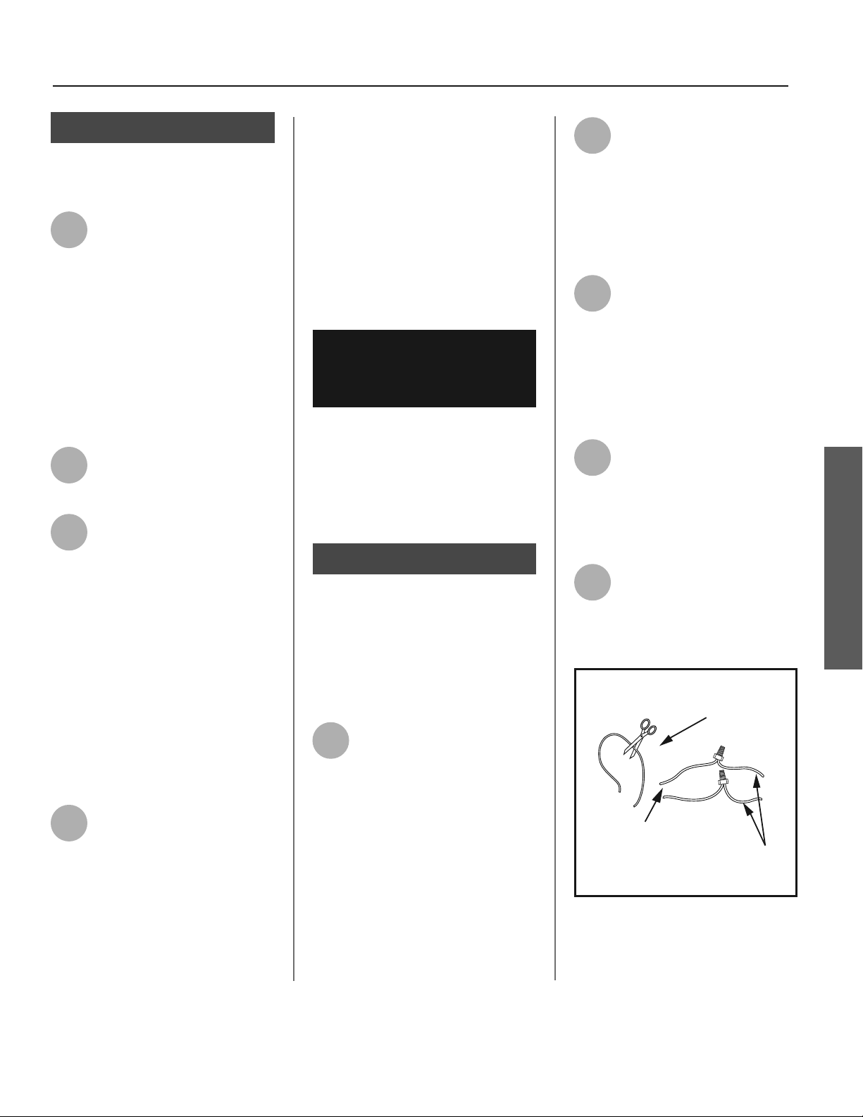
1
Locate the white 22 AWG wire
loop inside the condensate
drain access compartment by
removing the 4 screws a aching the
condensate drain access cover to the
unit. Cut the loop and strip insula on
off the 2 ends (Figures 14 & 15 on page
11).
2
Measure the distance from
the condensate drain access
cover to the condensate
pump, and cut two 22 AWG wires to
correct length and strip the insula on
at both ends. Thread both ends
through the grommet on the drain pan
cover.
3
Connect these 2 wires to the
2 wires on the water heater
using wire nuts or other con-
nectors. Reinstall the condensate drain
access cover and keep the connec on
joints inside of the cover.
4
Connect the free ends of the
2 wires to the shut off switch
on the condensate pump in
accordance with the condensate pump
manufacturers recommenda ons.
Condensate Pump Wiring Loop
22 AWG - White
(Loop Located Close to the Drain Connections)
White Wires
From Water Heater
Wires to Condensate
Pump Overflow
Shut Off Switch
(22 AWG or Larger)
Figure 14 - Wiring Loop for connec on of
Condensate Pump.
INSTALLATION
 Loading...