


 R
R
EN
10.1" DVD/HDMI/USB REAR SEAT ENTERTAINMENT SYSTEM
PKG-RSE3HDMI
ES
INSTALLATION MANUAL
FR
DIGITAL VIDEO
Please read before installing this equipment.
Manual de instalación
Leealo antes de utilizar equipe.
Guide d'installation
Veuillez lire avant d'utiliser cet appareil.
ALPINE ELECTRONICS MARKETING, INC.
1-7 Yukigaya-Otsukamachi, Ota-ku
Tokyo 145-0067, Japan
Tel.: 03-5499-4531
ALPINE Electronics of America, inc.
19145 Gramercy Place
Torrance, California 90501 U.S.A.
Tel.: 1-800-ALPINE-1 (1-800-257-4631)
ALPINE ELECTRONICS (BENELUX) GmbH
Leuvensesteenweg 510-B6,
1930 Zaventem, Belgium
Tel.: 02-725 1315
ALPINE electronics of australia pty, ltd. |
ALPINE ELectronics France S.a.r.l. |
161-165 Princess Highway, Hallam |
(RCS PONTOISE B 338 101 280) |
Victoria 3803, Australia |
98, Rue de la Belle Etoile, Z.I. Paris Nord II, |
Tel.: 03-8787-1200 |
B.P. 50016, 95945 Roissy Charles de Gaulle |
|
Cedex, France |
ALPINE Electronics GmbH |
Tel.: 01-48638989 |
Wilhelm-Wagenfeld-Strase 1-3 |
ALPINE Italia S.p.a. |
80807 München, Germany |
|
Tel.: 089-32 42 640 |
Viale C. Colombo 8, 20090 Trezzano |
|
Sul Naviglio (MI), Italy |
ALPINE electronics of u.k., ltd. |
Tel.: 02-484781 |
ALPINE House |
ALPINE ELECTRONICS DE ESPAÑa, S.A. |
Fletchamstead Highway, Coventry CCV4 9TW, U.K. |
|
Tel.: 0870-33 33 763 |
Portal de Gamarra 36, Pabellón, 32 |
|
01013 Vitoria (Alava)-APDO 133, Spain |
|
Tel.: 945-283588 |
|
Designed by Alpine Electronics of America, Inc. |
|
Printed In China |

Installation and Connections
Before installing or connecting the unit, please read the following thoroughly for proper use.
 Warning
MAKE THE CORRECT CONNECTIONS.
Failure to make the proper connections may result in fire or product damage.
USE ONLY IN CARS WITH A 12 VOLT NEGATIVE GROUND.
(Check with your dealer if you are not sure.) Failure to do so may result in fire, etc.
BEFORE WIRING, DISCONNECT THE CABLE FROM THE NEGATIVE BATTERY TERMINAL.
Failure to do so may result in electric shock or injury due to electrical shorts.
DO NOT ALLOW CABLES TO BECOME ENTANGLED IN SURROUNDING OBJECTS.
Arrange wiring and cables in compliance with the manual to prevent obstructions when driving. Cables or wiring that obstruct or hang up on places such as the steering wheel, gear lever, brake pedals, etc., can be extremely hazardous.
DO NOT SPLICE INTO ELECTRICAL CABLES.
Never cut away cable insulation to supply power to other equipment. Doing so will exceed the current carrying capacity of the wire and result in fire or electric shock.
DO NOT DAMAGE PIPE OR WIRING WHEN DRILLING HOLES.
When drilling holes in the chassis for installation, take precautions so as not to contact, damage or obstruct pipes, fuel lines, tanks or electrical wiring. Failure to take such precautions may result in fire.
DO NOT USE BOLTS OR NUTS IN THE BRAKE OR STEERING SYSTEMS TO MAKE GROUND CONNECTIONS.
Bolts or nuts used for the brake or steering systems (or any other safety-related system), or tanks should NEVER be used for installations or ground connections. Using such parts could disable control of the vehicle and cause fire, etc.
KEEP SMALL OBJECTS SUCH AS BATTERIES OUT OF THE REACH OF CHILDREN.
Swallowing them may result in serious injury. If swallowed, consult a physician immediately.
DO NOT INSTALL IN LOCATIONS WHICH MIGHT HINDER VEHICLE OPERATION, SUCH AS THE STEERING WHEEL OR SHIFT LEVER.
Doing so may obstruct forward vision or hamper movement, etc., and result in a serious accident.
CAUTION
CAUTION-Laser radiation when open, DO NOT STARE INTO BEAM
 Caution
HAVE THE WIRING AND INSTALLATION DONE BY EXPERTS.
The wiring and installation of this unit requires special technical skill and experience. To ensure safety, always contact the dealer where you purchased this product to have the work done.
USE SPECIFIED ACCESSORY PARTS AND INSTALL THEM SECURELY.
Be sure to use only the specified accessory parts. Use of other than designated parts may damage this unit internally or may not securely install the unit in place. This may cause parts to become loose resulting in hazards or product failure.
ARRANGE THE WIRING SO IT IS NOT CRIMPED OR PINCHED BY A SHARP METAL EDGE.
Route the cables and wiring away from moving parts (like the seat rails) or sharp or pointed edges. This will prevent crimping and damage to the wiring. If wiring passes through a hole in metal, use a rubber grommet to prevent the wires insulation from being cut by the metal edge of the hole.
DO NOT INSTALL IN LOCATIONS WITH HIGH MOISTURE OR DUST.
Avoid installing the unit in locations with high incidence of moisture or dust. Moisture or dust that penetrates into this unit may result in product failure.
Precautions
•Be sure to disconnect the cable from the (–) battery post before installing your PKG-RSE3HDMI. This will reduce any chance of damage to the unit in case of a short-circuit.
•Be sure to connect the color coded leads according to the diagram. Incorrect connections may cause the unit to malfunction or damage to the vehicle's electrical system.
•When making connections to the vehicle's electrical system, be aware of the factory installed components (e.g. on-board computer). Do not tap into these leads to provide power for this unit. When connecting the PKG-RSE3HDMI to the fuse box, make sure the fuse for the intended circuit of the PKGRSE3HDMI has the appropriate amperage. Failure to do so may result in damage to the unit and/or the vehicle. When in doubt, consult your ALPINE dealer.
•The PKG-RSE3HDMI uses female RCA-type jacks for connection to other units (e.g. AV head unit) having RCA connectors. You may need an adaptor to connect other units. If so, please contact your authorized ALPINE dealer for assistance.
IMPORTANT
Please record the serial number of your unit in the space provided below and keep it as a permanent record. The serial number plate is located on the bottom of the unit.
SERIAL NUMBER:
INSTALLATION DATE:
INSTALLATION TECHNICIAN:
PLACE OF PURCHASE:
2-EN

Accessories
Check accessory parts.
AV Input Connector |
AV Output Connector Power Connector |
|||||||||||||||||||||
|
|
|
|
|
|
|
|
|
|
|
|
|
|
|
|
|
|
|
|
|
|
|
|
|
|
|
|
|
|
|
|
|
|
|
|
|
|
|
|
|
|
|
|
|
|
|
|
|
|
|
|
|
|
|
|
|
|
|
|
|
|
|
|
|
|
|
|
|
|
|
|
|
|
|
|
|
|
|
|
|
|
|
|
|
|
|
|
|
|
|
|
|
|
|
|
|
|
|
|
|
|
|
|
|
|
|
|
|
|
|
|
|
|
|
|
|
|
|
|
|
|
|
|
|
|
|
|
|
|
|
|
|
|
|
|
|
|
RUE-4159H Universal |
SHS-N106 Single |
Installation Bracket |
|||
Remote Control |
Source Fold -Flat |
|
|||
|
|
|
|
Wireless Headphones |
|
MONITOR |
|
|
DEVICE |
|
|
|
|
MUTE |
|
|
|
|
|
SOURCE |
|
|
|
|
|
DVD |
USB |
|
|
HDMI1 |
HDMI2 |
AUX |
|
|
|
|
MONITOR |
|
|
|
|
|
DVD.CMD |
PIC.M |
|
|
|
DVD-HU EXT-DVD |
DTV |
|
|
||
EPG |
|
|
SETUP |
|
|
TOP.M |
|
|
MENU |
|
|
|
|
ENTER |
|
|
|
DISP |
|
|
RETURN |
|
|
INFO |
|
|
EXIT |
|
|
REPEAT |
CH |
CH |
SCAN |
|
|
AUDIO |
SUB.T ANGLE |
|
|
||
|
TEXT |
BACK |
|
|
|
1 |
2 |
3 |
4 |
|
|
5 |
6 |
7 |
8 |
|
|
9 |
0 |
+10 |
CLR |
|
|
|
RUE-4159H |
|
|
|
|
|
|
|
|
X 2 |
|
Trim Ring |
|
|
|
Screws (for |
Screws (for Trim Ring) |
|
|
|
|
Installation Bracket) |
|
|
|
X 4 |
X 5 |
AAA Batteries |
Optional FM |
Quick Start |
HDMI/USB |
|
Switching Box |
Guide, |
Cover Plate |
|
|
Installation |
|
|
|
Manual, |
|
|
|
Registration |
|
|
|
Card |
|
|
Sold |
|
|
|
Separately |
|
|
|
Part No. |
|
|
X 6 |
TMXR2000FMSB |
|
|
|
|
|
|
TMX-R3300HDMI Overhead |
FM Transmitter |
Optional |
|
Monitor |
|
Antenna Wire |
KCU-315UH |
|
|
|
HDMI/USB |
|
|
|
Extension |
|
|
|
Connector |
|
|
|
Sold |
|
|
|
Separately |
Top |
Right side |
Left side |
Rear |
interchangeable |
interchangeable |
interchangeable |
interchangeable |
cover |
cover |
cover |
cover |
X 3 |
X 3 |
X 3 |
X 3 |
(Color of Interchangeable cover: high gloss gun metal black, high gloss bright gray, high gloss champagne gold)
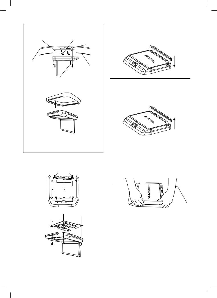
Installing the Overhead Monitor
1 Install the metal installation bracket to the ceiling.
4 screws will be used to attach the bracket to the ceiling. The protruding screw holes should be facing down, away from the ceiling. Ensure that the bracket is affixed to the roof supports behind the headliner and exercise caution to avoid drilling into the roof of the vehicle.
 Front
Front
Protruding screw holes.
2 Install the top interchangeable color cover.
Open the monitor lid.
Attach the cover to the monitor from the front (side facing the panel open button).
Push the sides of the cover into place.
Close the monitor lid and push the back of the cover into place.
3 Install both side panels of the interchangeable color covers.
Align and insert the notches on the panels into the grooves on the monitor body.
Slide the cover in the direction towards the front control keys at the front of the unit and snap the notch into place. A click should be heard.
3-EN
Optional
M4 Tapping Screws Mounting Bracket (Not included: screw
length depends on vehicle)
Roof Support
Vehicle Roof
Headliner
M4 x 13 Machined Screws (4) (Included)
Install trim ring before attaching the overhead monitor to the metal installation bracket.
The trim ring is used to make the monitor sit flush against the ceiling contour. Ask ALPINE dealer for detail.
Screw the shroud to the monitor body using the provided screws.
4 Install the overhead monitor to the ceiling.
Connect the cables and then install 4 screws to the metal installation bracket.
Rear screw holes
Front screw holes (underneath LCD screen)
(Left rear screw not illustrated)
5 Install the rear interchangeable color cover.
Align the openings on the cover with the rear button panel. Press down firmly to snap the cover into place.
Ensure that all notches have gone into their grooves properly.
Removing Interchangeable Color Cover
1 Remove the rear interchangeable color cover.
Reach across the monitor body and grasp the rear panel.
Gently lift the panel until it snaps off from the body.
2 Remove both side panels of the interchangeable color covers.
Grasp side cover as illustrated.
Raise the corner touching the rear control panel a few millimeters and gently slide the cover out.
Do not immediately lift the cover before sliding it. The notches will be damaged.
A small flat screwdriver or similar tool can be used to raise the corner of the panel.
4-EN

3 Remove the top interchangeable color cover.
Exercise caution when removing the top plate.
-The LCD screen must be fully closed during removal.
-Begin removal from the rear of the panel (side facing the 3 button panel).
-Removal by hand or by using soft tools is recommended as hard tools may scratch the panel surface.
-Grasp the cover by the indentations and pull gently until the cover snaps off from the LCD screen.
Mount Side
Dome Light
Polarity Switch
+ S W -
(Detail of dome light polarity switch)
AV Connector Ports
Connecting the Wireless Transmitter Wire
When listening to audio from vehicle speaker via FM radio, connect included wireless transmitter wire and change the antenna direction to get the best reception.
•FM reception performance depends on the vehicle antenna location and position of the wireless transmitter wire. If the reception is not good, please use optional FM Switching Box (Part No.:TMXR2000FMSB).Then, the wireless transmitter wire must
be removed.
AV Input |
AV Output |
HDMI1 Input |
Wireless |
|
Connector |
Connector |
Connector |
Transmitter |
|
|
|
|
Wire* |
|
|
|
|
|
|
|
|
|
|
|
Power Screw for pre- |
FM Switching |
venting loose |
Box Mini Plug |
connection |
(Option) |
(Detail of AV connector ports)
5-EN

Dome Light Wire (Green)
The dome light wire connects the built-in dome light to the cable from the vehicle’s dome light Switch. Polarity change switch is located on the top surface that mounts into the headliner.
Vehicle door polarity depends on the vehicle type. The polarity can be changed by the “Door SW polarity” switch. (Default: Negative Switched System)
Polarity +: When door open, door signal is 12V Polarity -: When door open, door signal is GND
Polarity+ |
When the door is open -> |
|
|
|
|
the door signal is 12 |
|
|
|
Vehicle |
Vehicle Door SW |
|
|
FUSE (5A) |
|
Door Closed |
|
1) BATT |
(Yellow) |
|
|
Door |
2) ACC |
(Red) |
|
Door Open |
3) GND |
(Black) |
|
|
|
4) DOOR |
(Green) |
|
Polarity- |
When the door is open -> |
|
|
|
|
the door signal is GND |
|
|
|
Vehicle |
Vehicle Door SW |
|
|
FUSE (5A) |
|
Door Closed |
|
1) BATT |
(Yellow) |
GND |
|
Door |
2) ACC |
(Red) |
|
3) GND |
(Black) |
||
|
Door Open |
4) DOOR |
(Green) |
6-EN
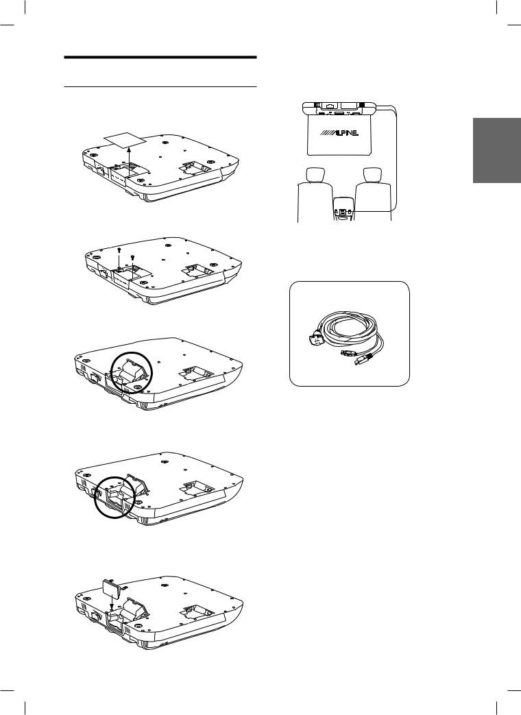
Permanent Installation of USB and
HDMI2
If desired, the second HDMI input may be permanently wired through the headliner.
1 Remove the cover.
2 Remove 2 screws.
3 Pull entire portion.
6 Connect the KCU-315UH HDMI/USB Extension Connector for PKG-RSE3HDMI (15 ft) (Sold separately).
MEDIA PLAY
KCU-315UH
HDMI/USB
Extension
Connector
Rear Center Console
Route the connector to the center console through B Pillar from inside of headliner.
KCU-315UH HDMI/USB
Extension Connector (15ft)
(Sold Separately)
4 Remove the door.
5 Install the HDMI/USB Cover Plate and tighten 2 screws.
7-EN

System Connections
|
|
|
|
|
|
|
|
|
|
|
|
|
|
|
|
To ALPINE |
|
|
|
To ALPINE |
|||||||||||||||||
|
|
|
|
|
|
|
|
|
|
|
|
|
|
|
|
AV/AVN Head |
|
|
|
AVN Head unit |
|||||||||||||||||
|
|
|
|
|
|
|
|
|
|
|
|
|
|
|
|
unit with AUX |
|
|
|
with HDMI |
|||||||||||||||||
|
|
|
|
|
|
|
|
|
|
|
|
|
|
|
|
Output or any |
Common for |
Output or any |
|||||||||||||||||||
To Secondary |
other AUX |
HDMI and |
HDMI Output |
||||||||||||||||||||||||||||||||||
Monitor(s) |
Output Devices |
AUX |
Devices |
||||||||||||||||||||||||||||||||||
|
|
|
|
|
|
|
|
|
|
|
|
|
|
|
|
|
|
|
|
|
|
|
|
|
|
|
|
|
|
|
|
|
|
|
|
|
|
|
|
|
|
|
|
|
|
|
|
|
|
|
|
|
|
|
|
|
|
|
|
|
|
|
|
|
|
|
|
|
|
|
|
|
|
|
|
|
|
|
|
|
|
|
|
|
|
|
|
|
|
|
|
|
|
|
|
|
|
|
|
|
|
|
|
|
|
|
|
|
|
|
|
|
|
|
|
|
|
|
|
|
|
|
|
|
|
|
|
|
|
|
|
|
|
|
|
|
|
|
|
|
|
|
|
|
|
|
|
|
|
|
|
|
|
|
|
|
|
|
|
|
|
|
|
|
|
|
|
|
|
|
|
|
|
|
|
|
|
|
|
|
|
|
|
|
|
|
|
|
|
|
Image |
AV OUTPUT |
AV INPUT |
USB Media Play |
HDMI2 INPUT with USB (5V) |
USB Storage |
USB Charge HDMI2 |
PKG-RSE3HDMI DVD |
|
MHL or |
Overhead Monitor |
|
|
|
Apple HDMI |
|
Media |
|
Adapter |
|
|
|
Streaming |
OR |
Smart |
Device |
||
|
|
Phone |
8-EN
 Loading...