


 Loading...
OmniSwitch® 8800
Getting Started Guide
060182-10, Rev. D
March 2005

Warning. Only personnel knowledgeable in basic electrical and mechanical procedures should install or maintain this equipment.
Lithium Batteries Caution. There is a danger of explosion if the Lithium battery in your chassis is incorrectly replaced. Replace the battery only with the same or equivalent type of battery recommended by the manufacturer. Dispose of used batteries according to the manufacturer’s instructions. The manufacturer’s instructions are as follows:
Return the module with the Lithium battery to Alcatel. The Lithium battery will be replaced at Alcatel’s factory.
The features and specifications described in this guide are subject to change without notice.
Copyright © 2005 by Alcatel Internetworking, Inc. All rights reserved. This document may not be reproduced in whole or in part without the express written permission of Alcatel Internetworking, Inc.
Alcatel® and the Alcatel logo are registered trademarks of Alcatel. Xylan®, OmniSwitch®, OmniStack®, and Alcatel OmniVista® are registered trademarks of Alcatel Internetworking, Inc.
OmniAccess™, Omni Switch/Router™, PolicyView™, RouterView™, SwitchManager™, VoiceView™, WebView™, X-Cell™, X-Vision™, and the Xylan logo are trademarks of Alcatel Internetworking, Inc.
This OmniSwitch product contains components which may be covered by one or more of the following U.S. Patents:
• U.S. Patent No. 6,339,830 |
|
|
|
• U.S. Patent No. 6,070,243 |
|
|
|
• U.S. Patent No. 6,061,368 |
|
|
|
• U.S. Patent No. 5,394,402 |
|
|
|
• U.S. Patent No. 6,047,024 |
|
|
|
• U.S. Patent No. 6,314,106 |
Alcatel Internetworking |
||
• U.S. Patent No. 6,542,507 |
|||
26801 West Agoura Road |
|||
|
Calabasas, CA 91301 |
||
|
(818) 880-3500 FAX (818) |
880-3505 |
|
|
US Customer Support: (800) |
995-2696 |
|
|
International Customer Support: (818) |
878-4507 |
|
|
Internet: http://eservice.ind.alcatel.com |
||

Table of Contents
OmniSwitch 8800. . . . . . . . . . . . . . . . . . . . . . . . 1
Features . . . . . . . . . . . . . . . . . . . . . . . . . . . . . . . . . . . 1
Hardware Features . . . . . . . . . . . . . . . . . . . . . . . 1
Availability Features . . . . . . . . . . . . . . . . . . . . . . 2
Installing the Hardware . . . . . . . . . . . . . . . 3
Items Required . . . . . . . . . . . . . . . . . . . . . . . . . . . . . 3
Site Preparation . . . . . . . . . . . . . . . . . . . . . . . . . . . . 3
Environmental Requirements . . . . . . . . . . . . . . . 3
Electrical Requirements . . . . . . . . . . . . . . . . . . . 3
Weight Considerations . . . . . . . . . . . . . . . . . . . . 4
Items Included . . . . . . . . . . . . . . . . . . . . . . . . . . . . . 4
Unpacking and Installing the Switch . . . . . . . . . . . . 5
Unpacking the Chassis . . . . . . . . . . . . . . . . . . . . 5
Recommendations . . . . . . . . . . . . . . . . . . . . 5
Chassis Removal Instructions . . . . . . . . . . . 5
Power Supply Removal Instructions . . . . . . 6
Lifting the Chassis . . . . . . . . . . . . . . . . . . . . . . . 7
Mounting the Switch . . . . . . . . . . . . . . . . . . . . . 7
Airflow Considerations . . . . . . . . . . . . . . . . 7
Module Access Considerations . . . . . . . . . . 8
Rack-Mounting . . . . . . . . . . . . . . . . . . . . . . 8
Stand-Alone . . . . . . . . . . . . . . . . . . . . . . . . 10
Installing Power Supplies . . . . . . . . . . . . . . . . . 10
Using the Grounding Wrist Strap and Chassis
Grounding Lug . . . . . . . . . . . . . . . . . . . . . . . . . 12
Installing the Network Interface (NI) and
Chassis Management Modules (CMMs) . . . . . .13 NI Modules . . . . . . . . . . . . . . . . . . . . . . . . .13 CMMs . . . . . . . . . . . . . . . . . . . . . . . . . . . . .13 Installing MiniGBIC Connectors . . . . . . . . . . .16 Installing Xenpak Modules . . . . . . . . . . . . . . . .17 Installing SFMs . . . . . . . . . . . . . . . . . . . . . . . . .18 Blank Cover Plates . . . . . . . . . . . . . . . . . . . . . .19
Connections and Cabling . . . . . . . . . . . . . 20
Serial Connection to the Console/Modem
Port . . . . . . . . . . . . . . . . . . . . . . . . . . . . . . . . . .20 Serial Connection Default Settings . . . . . .20 EMP Cable Requirements . . . . . . . . . . . . . . . . .21
Booting the Switch . . . . . . . . . . . . . . . . . . . . . . 22 Component LEDs . . . . . . . . . . . . . . . . . . . . . . .22
Your First Login Session . . . . . . . . . . . . . . . 23
Logging In to the Switch . . . . . . . . . . . . . . . . . . . . . 23 Setting IP Address Information for the EMP . . . . . 24
Unlocking Session Types . . . . . . . . . . . . . . . . . . . . 25 Unlocking All Session Types . . . . . . . . . . .25 Unlocking Specified Session Types . . . . . .25 How many sessions are allowed? . . . . . . . .26
Changing the Login Password . . . . . . . . . . . . . . . . 26 Setting the System Time Zone . . . . . . . . . . . . . . . . 27
March 2005 |
iii |
Setting the Date and Time . . . . . . . . . . . . . . . . . . . 27
Setting Optional System
Information . . . . . . . . . . . . . . . . . . . . . . . . . . . . . . . 28 Specifying an Administrative Contact . . . . . . . 28 Specifying a System Name . . . . . . . . . . . . . . . . 28 Specifying the Switch’s Location . . . . . . . . . . . 28
Viewing Your Changes . . . . . . . . . . . . . . . . . . . . . 29 Saving Your Changes . . . . . . . . . . . . . . . . . . . . . . . 29 Modifying the Serial Connection Settings . . . . . . . 29 CLI Basics . . . . . . . . . . . . . . . . . . . . . . . . . . . . . . . . . . 31
CLI Assistance Features . . . . . . . . . . . . . . . . . . . . . 31 Syntax Checking . . . . . . . . . . . . . . . . . . . . . . . . 31 Command Line (?) Help . . . . . . . . . . . . . . . . . . 32 Partial Keyword Completion . . . . . . . . . . . . . . 32 Deleting Characters . . . . . . . . . . . . . . . . . . . . . 32 Inserting Characters . . . . . . . . . . . . . . . . . . . . . 33 Previous Command Recall . . . . . . . . . . . . . . . . 33 Prefix Recognition . . . . . . . . . . . . . . . . . . . . . . 33 Prefix Prompt . . . . . . . . . . . . . . . . . . . . . . . . . . 34 Command History . . . . . . . . . . . . . . . . . . . . . . . 34 Command Logging . . . . . . . . . . . . . . . . . . . . . . 35
Enabling Command Logging . . . . . . . . . . . 35 Common CLI Commands . . . . . . . . . . . . . . . . . . . . 36
Offline Configuring . . . . . . . . . . . . . . . . . . . . . . . . . . . . 37 Syntax Checking . . . . . . . . . . . . . . . . . . . . . . . . 37 Scheduling a Configuration File to be Applied
at a Later Time . . . . . . . . . . . . . . . . . . . . . . . . . 37
Generating Snapshots of the
Current Configuration . . . . . . . . . . . . . . . . . . . . . . 37
Files and Directories . . . . . . . . . . . . . . . . . . . . 38 Boot and Image Files . . . . . . . . . . . . . . . . . . . . . . . . . . . 38 boot.params File . . . . . . . . . . . . . . . . . . . . . . . . . . . 38 boot.cfg File . . . . . . . . . . . . . . . . . . . . . . . . . . . . . . 38 Image Files . . . . . . . . . . . . . . . . . . . . . . . . . . . . . . . 39
Working and Certified Directories . . . . . . . . . . . . . . . . 40 Working Directory . . . . . . . . . . . . . . . . . . .40 Certified Directory . . . . . . . . . . . . . . . . . . .40 How can I tell which directory the switch is currently using? . . . . . . . . . . . . . . . . . . . . .41 Can I save changes to the Certified directory? . . . . . . . . . . . . . . . . . . . . . . . . . .41 What happens when the switch boots? . . . .41 Working and Certified Are Identical . . . . .41 Working and Certified Are Different . . . . .42 My Working and Certified directories are different. Can I force a reboot from the Working directory? . . . . . . . . . . . . . . . . . .42
Loading Software . . . . . . . . . . . . . . . . . . . . . . . 43 Non-Redundant Configurations . . . . . . . . . . . . . . . 43 Redundant Configurations . . . . . . . . . . . . . . . . . . . 44 Using WebView. . . . . . . . . . . . . . . . . . . . . . . . . . 46 Browser Compatibility . . . . . . . . . . . . . . . . . . . . . . 46 Required Image Files . . . . . . . . . . . . . . . . . . . . . . . 46 Logging In to WebView . . . . . . . . . . . . . . . . . . . . . 47 Navigating WebView . . . . . . . . . . . . . . . . . . . . . . . 47 Online Help . . . . . . . . . . . . . . . . . . . . . . . . . . . . . . . 49 Additional Information . . . . . . . . . . . . . . . . . . . . . . 49
iv |
March 2005 |
Troubleshooting . . . . . . . . . . . . . . . . . . . . . . . . . . . 49 The WebView login screen does not
display. . . . . . . . . . . . . . . . . . . . . . . . . . . . 49 The login screen displays, but my login attempt fails. . . . . . . . . . . . . . . . . . . . . . . . 49
Hardware Basics . . . . . . . . . . . . . . . . . . . . . . . . 50 Chassis Slot Numbering . . . . . . . . . . . . . . . . . . . . . 50 Chassis Management Module (CMM) . . . . . . . . . . . . . 51 CMM Redundancy . . . . . . . . . . . . . . . . . . . . . . . . . 52
CMM Slot Locations . . . . . . . . . . . . . . . . . . . . . . . 52 CMM Front Panel . . . . . . . . . . . . . . . . . . . . . . . 53
Switch Fabric Module (SFM) . . . . . . . . . . . . . . . . . . . . 54 SFM Redundancy . . . . . . . . . . . . . . . . . . . . . . . . . . 54
SFM Slot Locations . . . . . . . . . . . . . . . . . . . . . . . . 54 SFM Front Panel . . . . . . . . . . . . . . . . . . . . . . . . 55
Network Interface (NI) Modules . . . . . . . . . . . . . . . . . . 56 ENI Modules . . . . . . . . . . . . . . . . . . . . . . . . . . . . . 56
GNI Modules . . . . . . . . . . . . . . . . . . . . . . . . . . . . . 56 Miniature Gigabit Interface Converters (MiniGBICs) . . . . . . . . . . . . . . . . . . . . . . . . . . . 56
10GNI Modules . . . . . . . . . . . . . . . . . . . . . . . . . . . 57 Xenpaks . . . . . . . . . . . . . . . . . . . . . . . . . . . . . . 57
OS8-ENI-C24 Front Panel . . . . . . . . . . . . . . . . . . . 58 OS8-GNI-U8 Front Panel . . . . . . . . . . . . . . . . . . . . 59 OS8-GNI-C8 Front Panel . . . . . . . . . . . . . . . . . . . . 60
OS8-GNI-U24 Front Panel . . . . . . . . . . . . . . . . . . |
61 |
OS8-GNI-C24 Front Panel . . . . . . . . . . . . . . . . . . . 62
OS8-10GNI-UR1 Front Panel . . . . . . . . . . . . . . . . 63
User Documentation on CD. . . . . . . . . . . |
64 |
General Information . . . . . . . . . . . . . . . . . . . . . . . . |
65 |
March 2005 |
v |
vi |
March 2005 |
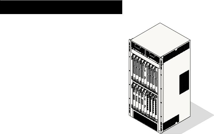
OmniSwitch 8800
Features
Alcatel’s OmniSwitch 8800 switches offer high performance 10/100 Ethernet and Gigabit Ethernet capabilities, as well as embedded server load balancing for enterprise requirements.
Both half-duplex and full-duplex modes are supported on all 10/100 Ethernet ports; full-duplex mode is supported on Gigabit Ethernet and 10 Gigabit Ethernet ports.
Hardware Features
The OmniSwitch 8800 is an 18-slot switch designed for the medium enterprise core or large wiring closet. The OmniSwitch 8800 offers up to 384 10/100 Ethernet ports, up to 384 Gigabit Ethernet ports, or up to 16 10 Gigabit Ethernet ports for use as a core switch.
The OmniSwitch 8800 chassis contains the following major components:
•16 Network Interface (NI) module slots
•Two Chassis Management Module (CMM) slots
•Five Switch Fabric Module (SFM) slots
•Two chassis (front) fan trays
•One fabric (rear) fan tray
•Power supply slot holding up to four power supplies
OmniSwitch 8800
March 2005 |
OmniSwitch 8800 1 |
Availability Features
Availability ensures that your switch is consistently operational for your day-to-day networking needs. This added reliability is provided through redundant components for critical hardware and software subsystems. OmniSwitch 8800 switches provide a broad variety of availability features, including:
•Software Redundancy
•Hardware Redundancy
•Configuration Redundancy
•Link Redundancy
•Smart Continuous Switching
•NI Module Forwarding During CMM Failover
•Image Rollback
•Hot Swapping
•Hardware Monitoring
•Power Checking Sequence
For more information on Availability features, refer to the
OmniSwitch 8800 Hardware Users Guide, the OmniSwitch 7700/7800/8800 Switch Management Guide, and the OmniSwitch 7700/7800/8800 Network Configuration Guide.
2 OmniSwitch 8800 |
March 2005 |

Installing the Hardware
Items Required |
Electrical Requirements |
•Grounding wrist strap (included)
•Phillips screwdriver (not included)
•Flat-blade screwdriver (not included)
•Serial cable (not included)
Site Preparation
Environmental Requirements
OmniSwitch 8800 switches have the following environmental and airflow requirements:
•The installation site must maintain a temperature between 0° and 45° Celsius (32° and 122° Fahrenheit) and not exceed 95 percent maximum humidity (noncondensing) at any time.
•Be sure to allow adequate room for proper air ventilation at the front, back, and sides of the switch. Refer to “Mounting the Switch” on page 7 for minimum clearance requirements. No clearance is necessary at the top or bottom of the chassis.
OmniSwitch 8800 switches have the following general electrical requirements:
•Each switch requires one grounded AC outlet for each power supply (up to four) installed in the chassis. OmniSwitch 8800 switches offer both AC and DC power supply support. Refer to the OmniSwitch 8800 Hardware Users Guide for more information.
•For switches using AC power connections, each supplied AC power cord is 2 meters (approximately 6.5 feet) long. Do not use extension cords.
Caution. In North America, OmniSwitch 8800 power supplies require 220 Volt power cords connected to 220 Volt power receptacles. Do not use 110 Volt power cords or receptacles.
Redundant AC Power. If possible, it is recommended that each AC outlet resides on a separate circuit. With redundant AC, if a single circuit fails, the switch’s remaining power supplies (on separate circuits) will likely be unaffected and can therefore continue operating.
March 2005 |
Installing the Hardware 3 |
Weight Considerations
When fully-populated (i.e., with all CMM, SFM, and NI modules, fan trays and power supplies installed), the OmniSwitch 8800 weighs approximately 220 lbs (100 Kgs).
Items Included
Your OmniSwitch 8800 order includes the following items:
•OmniSwitch chassis with factory-installed power supplies per order
•CMM module(s) per order
•Factory-installed SFM modules per order
•NI modules per order
•MiniGBICs per order, if applicable
•Xenpaks per order, if applicable
•Blank cover panels, if applicable
•Grounding wrist strap
•Power cord(s) per order, if applicable
•Hardcopy OmniSwitch 8800 Getting Started Guide
•Documentation CD containing the following manuals:
OmniSwitch 8800 Getting Started Guide OmniSwitch 8800 Hardware Users Guide OmniSwitch CLI Reference Guide
OmniSwitch 7700/7800/8800 Switch Management Guide
OmniSwitch 7700/7800/8800 Network Configuration Guide
OmniSwitch 7700/7800/8800 Advanced Routing Configuration Guide
4 Installing the Hardware |
March 2005 |
Unpacking and Installing the Switch
Unpacking the Chassis
To protect your switch components from electrostatic discharge (ESD) and physical damage, read all unpacking recommendations and instructions carefully before beginning.
Recommendations
•Unpack your OmniSwitch chassis as close as possible to the location where it will be installed.
•Network Interface (NI) modules and Chassis Management Modules (CMMs) are packaged in separate boxes. In order to greatly reduce exposure to electrostatic discharge (ESD) and physical damage, do not unpack these boxes until the CMMs and NI modules are ready to be installed.
Chassis Removal Instructions
1Begin by carefully cutting the tape along the seam marked “OPEN HERE FIRST.”
2Lift the box’s top flaps. Remove the smaller boxes that are enclosed and set them aside. These smaller boxes contain the Ship Kit.
3Next, completely remove the four white plastic inserts (two on the front and two on the back) from the sides of the box. Removing these inserts allows the overpack to be removed.
Caution. Do not attempt to lift the chassis with the white plastic inserts.
4The overpack is the outer shell of the packaging. Lift the overpack straight up until it slides free from the rest of the packaging. This allows easy access to the chassis.
5Remove the two rack-mounting brackets for 19-inch racks.
Note. See “Rack-Mounting” on page 8 for more information on installing the rack-mounting brackets.
6Carefully remove the protective plastic from the switch chassis.
7In order to reduce the weight of the chassis, it is recommended that you remove all factory-installed power supplies prior to lifting it from the packaging.
8Continue to “Power Supply Removal Instructions” on page 6.
Note. The subsection below applies to power supplies that are newly-shipped in the switch chassis. They have no power cords attached and the on/off switches are in the off ( O ) position. For instructions on removing power supplies that are currently operating in an existing switch, refer to your OmniSwitch 8800 Hardware Users Guide.
March 2005 |
Installing the Hardware 5 |
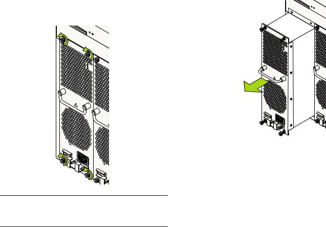
Power Supply Removal Instructions
1 Loosen the four captive screws, located at the four corners of the power supply’s front panel. If necessary, use a flat-blade screwdriver to loosen the screws. Be sure that all captive screws are completely disengaged from the threaded holes in the chassis before continuing.
!
230V |
|
50/60H |
z, 8 |
|
.0 A |
230V |
|
50/60H |
z, 8 |
|
.0 A |
Note. Alcatel provides factory-installed blank cover plates for empty module slots. Do not remove these cover plates as they play an important role in chassis ventilation.
2 With one hand, grasp the handle at the front of the power supply and slowly pull the power supply out of the power supply bay. Do not pull the power supply completely out of the bay with one hand.
TEM
FAIL
DC
 AC
AC
!
3When the power supply is pulled out far enough (about
10inches), place your other hand under the power supply casing to support its weight.
4Continue pulling the power supply out until it is removed from the chassis.
5Set the power supply aside on a clean, static-free surface. You will need to re-install it later.
6Remove all remaining power supplies by repeating steps 1 through 5.
7Continue to “Lifting the Chassis” on page 7.
6 Installing the Hardware |
March 2005 |
Lifting the Chassis
Once its weight has been reduced by removing the power supplies, the chassis can be lifted from the packaging material and moved to the location where it is to be installed (see important note below).
Important. Two people are required when lifting the chassis. Due to its weight, lifting the chassis unassisted can cause personal injury.
Continue to the next section, “Mounting the Switch.”
Mounting the Switch
Note. Due to their weight, access, and airflow requirements, OmniSwitch 8800 switches cannot be wallmounted.
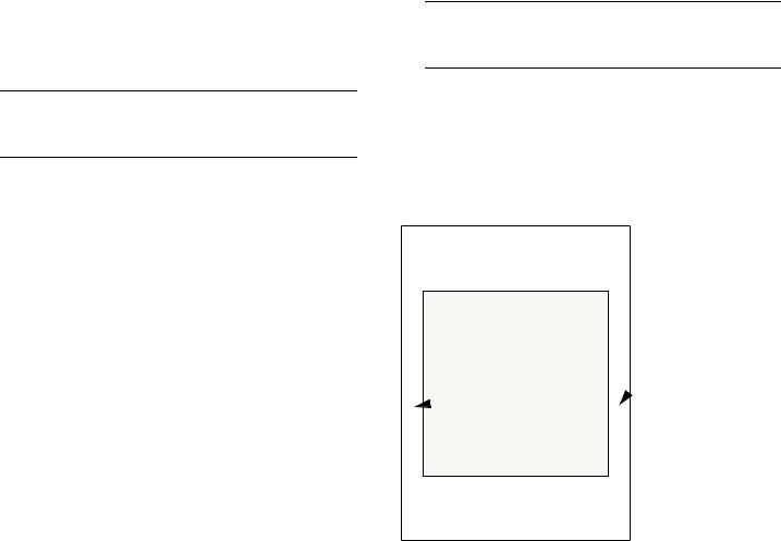
Airflow Considerations
Be sure that your switch is placed in a well-ventilated, staticfree environment. Always allow adequate clearance at the front and sides of the switch, as well as behind the switch’s fan unit (located at the top-rear of the chassis). The following topview diagram shows recommended minimum clearances for adequate airflow.
} |
Rear. 6 inches |
minimum at rear |
|
of chassis fan |
|
unit. |
Sides. 2 inches minimum at left and right sides.
} |
Front. 6 inches |
|
minimum at front |
|
of chassis. |
Chassis Top View
March 2005 |
Installing the Hardware 7 |

Never obstruct the air intake vents located at the bottom-front and bottom-sides of the chassis or the fan unit’s air output vents located at the rear of the chassis.
Note. Clearance is not required at the top and bottom of the chassis.
Module Access Considerations
If the switch will be mounted in rack that is immobile, make sure that you have adequate clearance to install and remove modules on the front and rear of the chassis. Please allow enough clearance to install and remove the front fan trays, which are approximately 15.8 inches long, are the longest modules on the front. And please allow enough clearance to remove the Switch Fabric Modules (SFMs) and power supplies, which are approximately 6 inches long.
Rack-Mounting
Refer to the important guidelines below before installing the OmniSwitch chassis in a rack.
•Rack-mounting the chassis requires three people—two people to hold the chassis and position it in the rack and a third person to secure the chassis to the rack using the attachment screws.
•Alcatel does not provide rack-mount screws. Use the screws supplied by the rack vendor.
•To prevent a rack from becoming top heavy, it is recommended that you install the switch at the bottom of the rack whenever possible.
•If you are installing the switch in a relay rack, be sure to install and secure the rack per the rack manufacturer’s specifications.
•Refer to page 7 for important chassis airflow recommendations before installing.
To rack-mount the switch, follow the steps below.
1Using the rack-mounting brackets as a template, mark the holes on the rack where the chassis is to be installed.
2Attach one rack-mounting bracket to the front end of the chassis using the Phillips-head screws that came with the chassis. See the figure below for the positioning and placement of these brackets and screws.
8 Installing the Hardware |
March 2005 |

3Attach the second bracket to the opposite front side of the chassis using the remaining screws.
4Using two people, lift and position the chassis until the rack-mount brackets are flush with the rack post.
5Align the holes in the brackets with the rack holes you marked in step 1.
6 Once the holes are aligned, use a third person to insert a screw through the bottom hole on each bracket. Tighten both screws until they are secure.
Note. Be sure to install the screws in the bottom hole of each bracket, as shown, before proceeding.
7 Once the screws at the bottom of each bracket are secure, install the remaining screws. Be sure that all screws are securely tightened.
March 2005 |
Installing the Hardware 9 |
Stand-Alone
The OmniSwitch 8800 can be installed unmounted as a standalone unit. Be sure that the installation location is a stable, flat surface that can accommodate the fully-populated weight of all switches being installed. One fully-populated OmniSwitch 8800 weighs approximately 220 lbs (100 Kgs).
Note. OmniSwitch 8800 switches must be installed “right side up.” Never attempt to operate a switch while it is lying on its side.
To install the switch as a stand-alone unit, follow the steps below:
1Use two or more people to move and position the unpopulated chassis upright on the floor or bench where it is to be installed.
2Be sure that adequate clearance has been provided for chassis airflow and that you have placed the chassis within reach of all required AC outlets. For recommended airflow allowances, refer to page 7. For environmental and electrical requirements, refer to page 3.
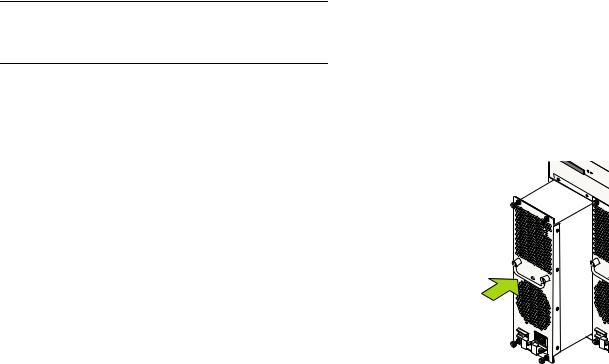
Installing Power Supplies
Reinstall the power supplies in the chassis power supply bays by following the steps below.
1Be sure that you do not install the power supply upside down. When orienting the power supply, note that the on/ off switch and power cord socket are located at the bottom of the power supply and the fan is located at the top of the power supply.
2With one hand, grasp the handle at the front of the power supply. Place your other hand under the power supply casing to support its weight.
3Carefully insert the rear of the casing into the power supply bay and slide the power supply back until its connector meets the chassis backplane connector.
!
10 Installing the Hardware |
March 2005 |

4Continue sliding the power supply back until the front panel meets the front of the chassis. Do not force the power supply into the bay. Otherwise you can damage the connectors.
5Tighten the four captive screws, located at the four corners of the power supply’s front panel. Be sure not to overtighten the captive screws. If you use a screwdriver, the torque used to tighten the screws must not exceed 2.3 inch pounds.
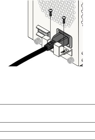
7 Remove the two screws on the top of the power cord retainer with a Phillips-head screwdriver. Do not discard these screws; you will need to reinstall them later.
Retainer Screws 
8 Slide the end of the power cord through the top portion of the retainer until it stops.
/60 |
Hz, 8. |
|
|
|
|
|
0 |
A |
|
|
6 Verify that the power supply’s on/off switch is in the off ( O ) position.
9 Plug the other end of the power cord into the power supply’s socket. Make sure that the power cord is attached securely to the outlet.
March 2005 |
Installing the Hardware 11 |
10 Use a Phillips-head screwdriver to attach the top portion of the retainer with the two Phillips-head screws.
11Once the power cord is secured in the retainer, plug the power cord into an easily-accessible, properly grounded outlet. Do not use an extension cord.
12Install all remaining power supplies by repeating steps
1through 11 for each power supply.
Note. For OmniSwitch 8800 switches using DC power, the power cord connector snaps into the connector socket. A cable retainer is not used.
Important. Do not turn on the power supplies at this time.
Using the Grounding Wrist Strap and Chassis
Grounding Lug
Because electrostatic discharge (ESD) can damage switch components such as the Network Interface (NI) and Chassis Management Modules, you must ground yourself properly before continuing with the hardware installation.
For this purpose, Alcatel provides a grounding wrist strap and a grounding lug located near the bottom-right of the chassis. To properly ground yourself, follow the steps below.
1Fasten the provided grounding strap to your wrist.
2Insert the wrist strap’s connector pin (located at the end of the strap’s tether) into the grounding lug near the bottom-right of the chassis, as shown.
12 Installing the Hardware |
March 2005 |

 Chassis
Grounding Lug
Important. For the grounding wrist strap to be effective in eliminating ESD, the power supplies must be installed in the chassis and plugged into grounded AC outlets as described on page 10.
Installing the Network Interface (NI) and
Chassis Management Modules (CMMs)
Once you are properly grounded, you may begin installing the Network Interface (NI) and CMM(s).
Note. See “Installing SFMs” on page 18 for information on installing SFMs.
NI Modules
NI modules may be installed in any slot position from 1 through 16 in OS8800 switches.
CMMs
CMMs may be installed in slots A or B in OS8800 switches. A minimum of one CMM is required for switch operations; the second CMM provides redundancy.
In non-redundant configurations, the CMM may be installed in either slot A or B. In redundant configurations, the CMM installed in slot A will be designated primary by default. For more information on redundancy, refer to page 52 or, for detailed information, refer to your OmniSwitch 8800 Hardware Users Guide.
NI modules cannot be installed in CMM slots A or B; likewise, CMMs cannot be installed in any NI slot position.
More Information on Slot Numbering. For a diagram showing the chassis layout and slot positions, refer to “Chassis Slot Numbering” on page 50.
March 2005 |
Installing the Hardware 13 |
Note. To further reduce exposure to electrostatic discharge (ESD) and physical damage, do not remove more than one module at a time from the factory packaging. Unpack one module, immediately install the module in the chassis, then repeat the sequence for another module.
Before beginning, note that the CMM modules and NI modules slide into the chassis card guides differently. With CMMs, the back of the module’s printed circuit board (which is wider than the front side) initially provides the glide path. When the printed circuit board narrows a sheet metal flange continues the remaining glide path. With NIs, the edges of the module’s printed circuit board slide into the guides.
CMM Glide Path
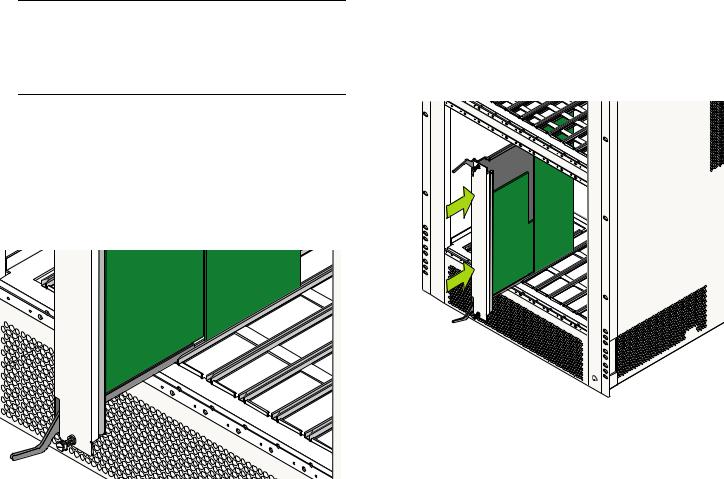
To install an NI or CMM module, follow the steps below.
1 Holding the module in both hands, carefully slide it into the chassis card guide. The component side of the board should face right.
2 The module should slide in easily. Do not force the module into the slot. If any resistance is encountered, ensure the module is aligned properly in the card guide. Also, see the important note regarding chassis card guides on page 14.
14 Installing the Hardware |
March 2005 |
3 When the module is nearly seated in the slot, be sure that the two extractor levers—one on top of the module and one on the bottom—are slightly opened (approximately 30 degrees). This allows the notch on each extractor lever to grasp the rail on the chassis. Once the notches have grasped the rail, press both extractor levers simultaneously until the module is firmly seated.
4 Once the module is firmly seated, secure the module to the chassis by tightening the two captive screws. Be sure not to overtighten the captive screws. If you use a screwdriver, the torque used to tighten the screws must not exceed 2.3 inch pounds.
5 Install all remaining modules by repeating steps 1 through 4 for each module.
March 2005 |
Installing the Hardware 15 |

Installing MiniGBIC Connectors
If you are installing an OS8-GNI-U8 or OS8-GNI-U24 module, you must install Miniature Gigabit Interface Converters (MiniGBICs) as required. These MiniGBICs are packaged separately.
TX
RX
MiniGBIC Module
To install a MiniGBIC follow the steps below.
1Be sure you have eliminated ESD by using the provided grounding wrist strap. Refer to “Using the Grounding Wrist Strap and Chassis Grounding Lug” on page 12 for more information.
2Holding the MiniGBIC by its sides, carefully slide it
into the desired GNI module universal MiniGBIC slot.
3 Push the MiniGBIC into the slot until it clicks into place.
GNI Module
LINK |
6 |
|
|
A C T |
|
|
|
|
LINK |
7 |
|
|
A C T |
|
|
MiniGBIC Slot |
|
LINK |
8 |
|
A C T |
|
|
|
|
|
|
|
|
|
LINK |
|
|
|
A C T |
 MiniGBIC Module
Note. There is a small removal handle at the front of the MiniGBIC transceiver. To remove a MiniGBIC, carefully lift this handle; then, grasp the handle and carefully pull the MiniGBIC from the module.
Caution. The MiniGBIC should slide in easily. Do not force it into the slot. If any resistance is encountered, ensure the MiniGBIC is aligned properly. Forcing the MiniGBIC into the slot can damage the unit, as well as components on your GNI module.
16 Installing the Hardware |
March 2005 |
Loading...