


 Loading...
OmniSwitch® 6600 Family
Getting Started Guide
060178-10, Rev. E
March 2005

Warning. Only personnel knowledgeable in basic electrical and mechanical procedures should install or maintain this equipment.
Lithium Batteries Caution. There is a danger of explosion if the Lithium battery in your chassis is incorrectly replaced. Replace the battery only with the same or equivalent type of battery recommended by the manufacturer. Dispose of used batteries according to the manufacturer’s instructions. The manufacturer’s instructions are as follows:
Return the module with the Lithium battery to Alcatel. The Lithium battery will be replaced at Alcatel’s factory.
The features and specifications described in this guide are subject to change without notice.
Copyright © 2005 by Alcatel Internetworking, Inc. All rights reserved. This document may not be reproduced in whole or in part without the express written permission of Alcatel Internetworking, Inc.
Alcatel® and the Alcatel logo are registered trademarks of Alcatel. Xylan®, OmniSwitch®, OmniStack®, and Alcatel OmniVista® are registered trademarks of Alcatel Internetworking, Inc.
OmniAccess™, Omni Switch/Router™, PolicyView™, RouterView™, SwitchManager™, VoiceView™, WebView™, X-Cell™, X-Vision™, and the Xylan logo are trademarks of Alcatel Internetworking, Inc.
This OmniSwitch product contains components which may be covered by one or more of the following U.S. Patents:
• U.S. Patent No. 6,339,830 |
|
|
|
• U.S. Patent No. 6,070,243 |
|
|
|
• U.S. Patent No. 6,061,368 |
|
|
|
• U.S. Patent No. 5,394,402 |
|
|
|
• U.S. Patent No. 6,047,024 |
|
|
|
• U.S. Patent No. 6,314,106 |
Alcatel Internetworking |
||
• U.S. Patent No. 6,542,507 |
|||
26801 West Agoura Road |
|||
|
Calabasas, CA 91301 |
||
|
(818) 880-3500 FAX (818) |
880-3505 |
|
|
US Customer Support: (800) |
995-2696 |
|
|
International Customer Support: (818) |
878-4507 |
|
|
Internet: http://eservice.ind.alcatel.com |
||

Table of Contents
OmniSwitch 6600 Family. . . . . . . . . . . . . . 1
Features . . . . . . . . . . . . . . . . . . . . . . . . . . . . . . . . . . . 1
Stand-Alone and Stacked
Configurations . . . . . . . . . . . . . . . . . . . . . . . . . . . . . 1
Stand-Alone . . . . . . . . . . . . . . . . . . . . . . . . . . . . 1
Stacked Configurations . . . . . . . . . . . . . . . . . . . . 2
Availability Features . . . . . . . . . . . . . . . . . . . . . . . . 2
Chassis Types . . . . . . . . . . . . . . . . . . . . . . . . . . . . . . 3
OmniSwitch 6624 (OS6624) . . . . . . . . . . . . . . . 3
OmniSwitch 6648 (OS6648) . . . . . . . . . . . . . . . 3
OmniSwitch 6600-U24 (OS6600-U24) . . . . . . . 4
OmniSwitch 6600-P24 (OS6600-P24) . . . . . . . . 4
OmniSwitch 6602-24 (OS6602-24) . . . . . . . . . . 5
OmniSwitch 6602-48 (OS6602-48) . . . . . . . . . . 5
Setting Up the Hardware. . . . . . . . . . . . . . 6
Items Required . . . . . . . . . . . . . . . . . . . . . . . . . . . . . 6
Site Preparation . . . . . . . . . . . . . . . . . . . . . . . . . . . . 6
Environmental Requirements . . . . . . . . . . . . . . . 6
Electrical Requirements . . . . . . . . . . . . . . . . . . . 6
Weight Considerations . . . . . . . . . . . . . . . . . . . . 7
OS6624 . . . . . . . . . . . . . . . . . . . . . . . . . . . . 7
OS6648 . . . . . . . . . . . . . . . . . . . . . . . . . . . . 7
OS6600-U24 . . . . . . . . . . . . . . . . . . . . . . . . 7
OS6600-P24 . . . . . . . . . . . . . . . . . . . . . . . . . 7
OS6602-24 . . . . . . . . . . . . . . . . . . . . . . . . . . 7
OS6602-48 . . . . . . . . . . . . . . . . . . . . . . . . . .7
Items Included . . . . . . . . . . . . . . . . . . . . . . . . . . . . . . 7 Optional Items . . . . . . . . . . . . . . . . . . . . . . . . . . .8
Unpacking and Initial Setup . . . . . . . . . . . . . . . . . . . 8 Unpacking the Chassis . . . . . . . . . . . . . . . . . . . .8 Recommendations . . . . . . . . . . . . . . . . . . . .8 Instructions . . . . . . . . . . . . . . . . . . . . . . . . . .9
Setting Up the Switch . . . . . . . . . . . . . . . . . . . . . . . . 9 Airflow Considerations . . . . . . . . . . . . . . . . . . . .9 Installing the Switch on a Tabletop or Bench . .10 Rack-Mounting the Switch . . . . . . . . . . . . . . . .11 Rack Mounting Stacked Configurations . . . . . .13
Installing a Back Up Power Supply
(OS6624, OS6648, OS6600-U24) . . . . . . . . . . . . . 14 Installing Uplink and Stacking Modules . . . . . . . . . 16 Installing MiniGBIC Connectors . . . . . . . . . . . . . . 18
Installing SFP Connectors
(OS6600-U24 Only) . . . . . . . . . . . . . . . . . . . . . . . . 20 Blank Cover Plates . . . . . . . . . . . . . . . . . . . . . . . . . 21
Connections and Cabling . . . . . . . . . . . . . 22
Connecting the Serial Cable to the Console Port . . 22 Serial Connection Default Settings . . . . . . . . . .22
The Next Step . . . . . . . . . . . . . . . . . . . . . . . . . . . . . 23
March 2005 |
iii |
Completing a Stacked
Configuration. . . . . . . . . . . . . . . . . . . . . . . . . . . . 24 Slot Assignment Guidelines . . . . . . . . . . . . . . . 24
Assigning Slot Numbers . . . . . . . . . . . . . . . . . . . . . . . . 25 Slot Numbering Example . . . . . . . . . . . . . . . . . . . . 26
Connecting Cables
to Stacking Modules . . . . . . . . . . . . . . . . . . . . . . . . . . . 27 Guidelines . . . . . . . . . . . . . . . . . . . . . . . . . . . . . . . . 27 Booting the Stack . . . . . . . . . . . . . . . . . . . . . . . . . . . . . 29 Booting Stand-Alone Switches . . . . . . . . . . . . . . . . . . . 29 Verifying LED Status. . . . . . . . . . . . . . . . . . . . 30
Component LEDs . . . . . . . . . . . . . . . . . . . . . . . . . . 30 Verifying Primary and Secondary Status . . . . . 30 PRI LED . . . . . . . . . . . . . . . . . . . . . . . . . . 30 SEC LED . . . . . . . . . . . . . . . . . . . . . . . . . . 31 Idle Status . . . . . . . . . . . . . . . . . . . . . . . . . 31
Your First Login Session. . . . . . . . . . . . . . . 32
Logging In to the Switch . . . . . . . . . . . . . . . . . . . . 32
Assigning an IP Address to the Switch or Stack . . 33 Assigning IP Addresses to Switches in a
Stacked Configuration . . . . . . . . . . . . . . . . . . . 34
Unlocking Session Types . . . . . . . . . . . . . . . . . . . . 34 Unlocking All Session Types . . . . . . . . . . . . . . 34 Unlocking Specified Session Types . . . . . . . . . 35 How many sessions are allowed? . . . . . . . . . . . 35
Changing the Login Password . . . . . . . . . . . . . . . . 35 Setting the System Time Zone . . . . . . . . . . . . . . . . 36 Setting the Date and Time . . . . . . . . . . . . . . . . . . . 36
Setting Optional System Information . . . . . . . . . . . 37 Specifying an Administrative Contact . . . . . . .37 Specifying a System Name . . . . . . . . . . . . . . . .37 Specifying the Switch’s Location . . . . . . . . . . .37
Viewing Your Changes . . . . . . . . . . . . . . . . . . . . . . 38 Saving Your Changes . . . . . . . . . . . . . . . . . . . . . . . 38 Modifying the Serial Connection Settings . . . . . . . 38 CLI Basics. . . . . . . . . . . . . . . . . . . . . . . . . . . . . . . . . . . 41
CLI Assistance Features . . . . . . . . . . . . . . . . . . . . . 41 Syntax Checking . . . . . . . . . . . . . . . . . . . . . . . .41 Command Line (?) Help . . . . . . . . . . . . . . . . . .42 Partial Keyword Completion . . . . . . . . . . . . . . .42 Deleting Characters . . . . . . . . . . . . . . . . . . . . . .42 Inserting Characters . . . . . . . . . . . . . . . . . . . . .43 Previous Command Recall . . . . . . . . . . . . . . . .43 Prefix Recognition . . . . . . . . . . . . . . . . . . . . . .43 Prefix Prompt . . . . . . . . . . . . . . . . . . . . . . . . . .44 Command History . . . . . . . . . . . . . . . . . . . . . . .44 Command Logging . . . . . . . . . . . . . . . . . . . . . .45
Enabling Command Logging . . . . . . . . . . .45 Common CLI Commands . . . . . . . . . . . . . . . . . . . . 46
Offline Configuring . . . . . . . . . . . . . . . . . . . . . . . . . . . . 47 Syntax Checking . . . . . . . . . . . . . . . . . . . . . . . .47 Scheduling a Configuration File to be Applied
at a Later Time . . . . . . . . . . . . . . . . . . . . . . . . .47
Generating Snapshots of the
Current Configuration . . . . . . . . . . . . . . . . . . . . . . . 47
iv |
March 2005 |
Files and Directories. . . . . . . . . . . . . . . . . . . . 48 Boot and Image Files . . . . . . . . . . . . . . . . . . . . . . . . . . . 48 boot.params File . . . . . . . . . . . . . . . . . . . . . . . . . . . 48 boot.cfg File . . . . . . . . . . . . . . . . . . . . . . . . . . . . . . 48 boot.slot.cfg File . . . . . . . . . . . . . . . . . . . . . . . . . . . 49 Image Files . . . . . . . . . . . . . . . . . . . . . . . . . . . . . . . 49
Working and Certified Directories . . . . . . . . . . . . . . . . 51 Working Directory . . . . . . . . . . . . . . . . . . . . . . 51 Certified Directory . . . . . . . . . . . . . . . . . . . . . . 51
How can I tell which directory the switch
is currently using? . . . . . . . . . . . . . . . . . . . 52 Can I save changes to the Certified
directory? . . . . . . . . . . . . . . . . . . . . . . . . . . . . . 52 What happens when the switch boots? . . . . . . . 52 Working and Certified Are Identical . . . . . . . . 52 Working and Certified Are Different . . . . . . . . 53 My Working and Certified directories are different. Can I force a reboot from the
Working directory? . . . . . . . . . . . . . . . . . . 53 Loading Software . . . . . . . . . . . . . . . . . . . . . . . 54 Stand-Alone Configurations . . . . . . . . . . . . . . . . . . 54
Stacked Configurations . . . . . . . . . . . . . . . . . . . . . 55 Certifying Your New Software . . . . . . . . . . . . . 56
Using WebView . . . . . . . . . . . . . . . . . . . . . . . . . 57 Browser Compatibility . . . . . . . . . . . . . . . . . . . . . . 57 Required Image Files . . . . . . . . . . . . . . . . . . . . . . . 57 Logging In to WebView . . . . . . . . . . . . . . . . . . . . . 58 Navigating WebView . . . . . . . . . . . . . . . . . . . . . . . 58
Online Help . . . . . . . . . . . . . . . . . . . . . . . . . . . . . . . 60
Additional Information . . . . . . . . . . . . . . . . . . . . . . 60
Troubleshooting . . . . . . . . . . . . . . . . . . . . . . . . . . . 60
The WebView login screen does not
display. . . . . . . . . . . . . . . . . . . . . . . . . . . .60
The login screen displays, but my login
attempt fails. . . . . . . . . . . . . . . . . . . . . . . .60
Hardware Basics . . . . . . . . . . . . . . . . . . . . . . . . 61
OmniSwitch 6624 Front Panel . . . . . . . . . . . . . . . . 61
OmniSwitch 6600-U24 Front Panel . . . . . . . . . . . . 62
OmniSwitch 6648 Front Panel . . . . . . . . . . . . . . . . 63
OmniSwitch 6600-P24 Front Panel . . . . . . . . . . . . 64
OmniSwitch 6602-24 Front Panel . . . . . . . . . . . . . . 65
OmniSwitch 6602-48 Front Panel . . . . . . . . . . . . . . 66
OmniSwitch 6600 Status LEDs . . . . . . . . . . . . . . . 67
March 2005 |
v |
vi |
March 2005 |

OmniSwitch 6600 Family
Features
The OmniSwitch 6600 Family (OS6624, OS6600-U24, OS6648, OS6600-P24, OS6602-24, and OS6602-48) are next generation enterprise edge/workgroup switches. These switches are based on the same software architecture as OmniSwitch 7000 and 8000 series switches (i.e., OS7700, OS7800, and OS8800). These switches are designed to meet the most stringent network requirements for mission-critical networks.
OmniSwitch 6600 Family switches are optimized for voice and data integration and provide non-blocking multi-Gigabit Ethernet capacity. Additional features include Carrier-class intelligence, best of breed QoS, Carrier-class resiliency, network management, and advanced policy-based VLANs and security. OmniSwitch 6600 Family switches also support wirespeed Layer 2 and Layer 3 switching, industry-based standards, and a full array of reliability, redundancy and resiliency capabilities.
Stand-Alone and Stacked
Configurations
Stand-Alone
A stand-alone OmniSwitch 6600 Family switch is ideal for small and medium-sized network edge applications, offering 24 10/100 ports (OS6624 and OS6602-24), 24 Power over Ethernet (PoE) ports (OS6600-P24), 48 10/100 (OS6648 and OS6602-48) ports, and 24 100 SFP ports (OS6600-U24). These switches provide support for enterprise-based devices, such as computer workstations or IP telephones.
A single OmniSwitch 6600 Family also supports two Gigabit Ethernet uplinks for high-bandwidth connections to a backbone or server.
March 2005 |
OmniSwitch 6600 Family 1 |

Stacked Configurations
In addition to working as individual, stand-alone switches, OmniSwitch 6600 Family switches can also be linked together to form a single, high-density virtual chassis known as a stack.
Stacking switches provides scalability by allowing users to quickly and easily expand 10/100 port density. Twenty-four 10/100 ports are added for each OS6624 brought into the stack; twenty-four 100 SFP ports are added for each OS6600U24; forty-eight 10/100 ports are added for each OS6648.
Up to eight switches can be stacked. OmniSwitch 6600 Family switches can be mixed and matched in any combination within the stack. This provides a virtual chassis with a 10/100 or 100 capacity of up to 384 ports.
As with the stand-alone configuration, a stacked virtual chassis configuration provides Gigabit Ethernet uplinks to a backbone or server.
Note. For basic information on stacking OmniSwitch 6600 Family switches into a virtual chassis, refer to “Completing a Stacked Configuration” on page 24.
For additional information, refer to the OmniSwitch 6600 Family Hardware Users Guide.
Availability Features
The OmniSwitch 6600 Family provides a broad variety of Availability features. Availability features are hardwareand software-based safeguards that help prevent the loss of data flow in the event of a subsystem failure.
In addition, some Availability features allow you to maintain or replace hardware components without powering off your switch or interrupting switch operations.
Combined, these features provide added resiliency and help ensure that your switch is consistently available for your day- to-day network operations.
Hardware-related Availability features include:
•Smart Continuous Switching
•Software Rollback
•Hot Swapping
•Hardware Monitoring
For information on these Availability features, refer to the
OmniSwitch 6600 Family Hardware Users Guide.
2 OmniSwitch 6600 Family |
March 2005 |

Chassis Types
OmniSwitch 6624 (OS6624)
The OS6624 is a stackable edge/workgroup switch offering 24 10/100 Ethernet ports. The OS6624 can also be equipped with up to four Gigabit Ethernet ports for connections to a high speed backbone or server.
 OmniSwitch 6624
|
CONSOLE |
|
|
|
|
|
|
|
|
|
|
|
EXPANSION |
|
EXPANSION/STACKING |
|
|
|
|
|
|
|
|
|
|
|
|
|
|
|
|||
|
|
|
|
|
|
|
|
|
|
|
|
|
25 |
26 |
2 7 |
2 8 |
|
|
1 |
3 |
5 |
7 |
9 |
11 |
13 |
15 |
17 |
19 |
21 |
23 |
|
|
|
OK1 |
PS1 PRI TEMP |
|
|
|
|
|
|
|
|
|
|
|
|
LINK/ACT |
|
LINK/ACT |
|
|
|
|
|
|
|
|
|
|
|
|
|
LINK/ACT |
LINK/ACT |
||
OK2 |
PS2 SEC FAN |
SEL |
4 |
6 |
8 |
10 |
12 |
|
|
|
|
|
|
|
|
|
|
|
2 |
14 |
16 |
18 |
20 |
22 |
24 |
|
|
|
|||||
The OS6624 chassis contains the following components:
•Console port (DB-9)
•Stack indicator and status LEDs
•24 10/100 Ethernet ports
•One slot for OS6600-GNI-U2 (fiber) or OS6600-GNI- C2 (copper) Gigabit Ethernet uplink module
•One slot for a Gigabit Ethernet uplink module as described above or a stacking module
•Factory-installed power supply
•Bay for optional back up power supply
•Built-in fan tray with three fans
•Grounding block for type LCD8-10A-L grounding lug
OmniSwitch 6648 (OS6648)
The OS6648 is a stackable edge/workgroup switch offering 48 10/100 Ethernet ports. The OS6648 can also be equipped with up to four Gigabit Ethernet ports for connections to a high speed backbone or server.
|
|
25 |
27 |
29 |
31 |
33 |
35 |
37 |
39 |
41 |
43 |
45 |
47 |
|
|
|
|
OmniSwitch 6648 |
|
|
|
|
|
|
|
|
|
|
|
|
|
|
|
||
|
|
|
|
|
|
|
|
|
|
|
|
|
|
LINK/ACT |
LINK/ACT |
|
|
|
CONSOLE |
|
|
|
|
|
|
|
|
|
|
|
|
|
|
EXPANSION/STACKING |
|
|
|
|
|
|
|
|
|
|
|
|
|
|
|
|
|
||
|
|
26 |
28 |
30 |
32 |
34 |
36 |
38 |
40 |
42 |
44 |
46 |
48 |
49 |
50 |
5 1 |
5 2 |
|
|
1 |
3 |
5 |
7 |
9 |
11 |
13 |
15 |
17 |
19 |
21 |
23 |
EXPANSION |
|
|
|
OK1 |
PS1 PRI TEMP |
|
|
|
|
|
|
|
|
|
|
|
|
|
|
|
LINK/ACT |
|
|
|
|
|
|
|
|
|
|
|
|
|
|
|
|
LINK/ACT |
|
OK2 |
PS2 SEC FAN |
SEL |
|
|
|
|
|
|
|
|
|
|
|
|
|
|
|
|
|
2 |
4 |
6 |
8 |
10 |
12 |
14 |
16 |
18 |
20 |
22 |
24 |
|
|
|
|
The OS6648 chassis contains the following components:
•Console port (DB-9)
•Stack indicator and status LEDs
•48 10/100 Ethernet ports
•One slot for OS6600-GNI-U2 (fiber) or OS6600-GNI- C2 (copper) Gigabit Ethernet uplink module
•One slot for a Gigabit Ethernet uplink module as described above or a stacking module
•Factory-installed power supply
•Bay for optional back up power supply
•Built-in fan tray with three fans
•Grounding block for type LCD8-10A-L grounding lug
March 2005 |
OmniSwitch 6600 Family 3 |

OmniSwitch 6600-U24 (OS6600-U24)
The OS6600-U24 is a stackable edge/workgroup switch offering 24 100 SFP Ethernet ports. The OS6600-U24 can also be equipped with up to four Gigabit Ethernet ports for connections to a high speed backbone or server.
OmniSwitch 6600-U24 |
|
|
|
|
|
|
|
|
|
|
|
|
|
|
|
|
|
|
|
|
|
|
|
|
|
|
|||
|
|
|
|
1 |
|
3 |
|
5 |
|
7 |
|
9 |
11 |
|
13 |
|
|
15 |
17 |
|
|
19 |
|
21 |
23 |
|
EXPANSION |
EXPANSION/STACKING |
|
|
|
|
|
|
|
|
|
|
|
|
|
|
|
25 |
26 |
2 7 |
2 8 |
||||||||||||
|
CONSOLE |
|
|
|
|
|
|
|
|
|
|
|
|
|
|
|
|
|
|
|
|
|
|
|
|
|
|
|
|
|
|
SEL |
|
|
|
|
|
|
|
|
|
|
|
|
|
|
|
|
|
|
|
|
|
|
|
|
|
|
|
OK1 |
PS1 |
2 |
|
|
|
|
|
|
|
|
|
|
|
|
|
|
|
|
|
|
|
|
|
|
|
24 |
|
|
|
|
|
|
|
|
|
|
|
|
|
|
|
|
|
|
|
|
|
|
|
|
|
|
|
|
|
|
|
LINK/ACT |
LINK/ACT |
OK2 |
PS2 PRI SEC FAN TEMP |
1 |
2 |
3 |
4 |
5 |
6 |
7 |
8 |
9 |
10 |
11 |
12 |
13 |
14 |
15 |
16 |
17 |
18 |
19 |
20 |
21 |
22 |
23 |
24 |
|
|
|
|
The OS6600-U24 chassis contains the following components:
•Console port (RJ-45)
•Stack indicator and status LEDs
•24 100 Ethernet SFP ports
•One slot for OS6600-GNI-U2 (fiber) or OS6600-GNI- C2 (copper) Gigabit Ethernet uplink module
•One slot for a Gigabit Ethernet uplink module as described above or a stacking module
•Factory-installed power supply
•Bay for optional back up power supply
•Built-in fan tray with three fans
•Grounding block for type LCD8-10A-L grounding lug
OmniSwitch 6600-P24 (OS6600-P24)
The OS6600-U24 is a stackable edge/workgroup switch offering 24 Power over Ethernet (PoE) 10/100 Ethernet ports. The OS6600-P24 can also be equipped with up to four Gigabit Ethernet ports for connections to a high speed backbone or server.
|
OmniSwitch 6600-P24 |
|
|
|
|
|
|
|
|
|
|
|
|
|
|
||
|
|
|
|
|
|
|
|
|
|
|
|
|
|
EXPANSION |
|
EXPANSION/STACKING |
|
|
|
|
|
|
|
|
|
|
|
|
|
|
|
25 |
26 |
2 7 |
2 8 |
|
|
|
1 |
3 |
5 |
7 |
9 |
11 |
13 |
15 |
17 |
19 |
21 |
23 |
|
|
|
|
CONSOLE |
|
|
|
|
|
|
|
|
|
|
|
|
|
|
|
|
|
|
SEL |
|
|
|
|
|
|
|
|
|
|
|
|
|
|
|
OK1 |
PS1 |
|
|
|
|
|
|
|
|
|
|
|
|
|
LINK/ACT |
|
LINK/ACT |
|
|
|
|
|
|
|
|
|
|
|
|
|
|
LINK/ACT |
LINK/ACT |
||
OK2 |
PS2 |
PRI SEC |
FAN TEMP |
4 |
6 |
8 |
10 |
12 |
|
|
|
|
|
|
|
|
|
|
|
|
2 |
14 |
16 |
18 |
20 |
22 |
24 |
|
|
|
|||||
The OS6600-U24 chassis contains the following components:
•Console port (RJ-45)
•Stack indicator and status LEDs
•24 10/100 PoE ports
•One slot for OS6600-GNI-U2 (fiber) or OS6600-GNI- C2 (copper) Gigabit Ethernet uplink module
•One slot for a Gigabit Ethernet uplink module as described above or a stacking module
•Factory-installed power supply
•Connector for optional back up power supply
•Built-in fan tray with three fans
•Grounding block for type LCD8-10A-L grounding lug
4 OmniSwitch 6600 Family |
March 2005 |
OmniSwitch 6602-24 (OS6602-24)
The OS6602-24 is a stackable edge/workgroup switch offering 24 10/100 Ethernet ports. The OS6602-24 can also be equipped with up to two Gigabit Ethernet ports for connections to a high speed backbone or server.
OmniSwitch 6602-48 (OS6602-48)
The OS6602-48 is a stackable edge/workgroup switch offering 48 10/100 Ethernet ports. The OS6602-48 can also be equipped with up to two Gigabit Ethernet ports for connections to a high speed backbone or server.
2 |
3 |
4 |
5 |
6 |
7 |
8 |
9 |
10 |
11 |
12 |
13 |
14 |
15 |
16 |
17 |
18 |
19 |
20 |
21 |
22 |
23 |
24 |
OmniSwitch 6602-24 |
|
|
1 |
2 |
3 |
4 |
5 |
6 |
7 |
8 |
9 |
10 |
11 |
12 |
13 |
14 |
15 |
16 |
17 |
18 |
19 |
20 |
21 |
22 |
23 |
24 |
25 |
26 |
28 |
29 |
30 |
31 |
32 |
33 |
34 |
35 |
36 |
37 |
38 |
39 |
40 |
41 |
42 |
43 |
44 |
45 |
46 |
47 |
48 |
OmniSwitch 6602-48 |
||
|
|
|
|
|
|
|
|
|
|
|
|
|
|
|
|
|
|
|
|
|
|
|
|
C |
|
|
1 |
|
|
|
|
|
|
|
|
|
|
|
|
|
|
|
|
|
|
|
|
|
|
|
|
|
|
|
|
|
|
|
|
|
|
|
|
|
|
|
|
|
|
|
|
|
|
||
|
|
|
|
|
|
|
|
|
|
|
|
|
|
|
|
|
|
|
|
|
|
|
|
|
|
|
|
|
|
|
|
|
|
|
|
|
|
|
|
|
|
|
|
|
|
|
|
|
|
|
|
|
|
|
|
|
|
|
|
|
|
|
|
|
|
|
|
|
|
|
|
|
|
C |
|
|
|
|
|
|
|
|
|
|
|
|
|
|
|
|
|
|
|
|
|
|
|
|
|
o |
Sel |
|
|
|
|
|
|
|
|
|
|
|
|
|
|
|
|
|
|
|
|
|
|
|
|
|
|
|
|
|
|
|
|
|
|
|
|
|
|
|
|
|
|
|
|
|
|
|
|
|
o |
|
|
|
|
|
|
|
|
|
|
|
|
|
|
|
|
|
|
|
|
|
|
|
|
n |
|
OK1 PS1 |
PR1 TMP |
|
|
|
|
|
|
|
|
|
|
|
|
|
|
|
|
|
|
|
|
|
|
|
|
|
|
|
|
|
|
|
|
|
|
|
|
|
|
|
|
|
|
|
|
|
|
|
n |
|
|
|
|
|
|
|
|
|
|
|
|
|
|
|
|
|
|
|
|
|
|
|
|
s |
|
|
|
|
|
|
|
|
|
|
|
|
|
|
|
|
|
|
|
|
|
|
|
|
|
|
|
|
|
|
|
|
|
|
|
|
|
|
|
|
|
|
|
|
|
|
|
|
s |
||
|
|
|
|
|
|
|
|
|
|
|
|
|
|
|
|
|
|
|
|
|
|
|
|
o |
|
|
|
|
|
|
|
|
|
|
|
|
|
|
|
|
|
|
|
|
|
|
|
|
|
|
|
|
|
|
|
|
|
|
|
|
|
|
|
|
|
|
|
|
|
|
|
|
|
|
o |
|
|
|
|
|
|
|
|
|
|
|
|
|
|
|
|
|
|
|
|
|
|
|
|
l |
|
OK2 PS2 SEC FAN |
|
|
|
|
|
|
|
|
|
|
|
|
|
|
|
|
|
|
|
|
|
|
|
|
|
|
|
|
|
|
|
|
|
|
|
|
|
|
|
|
|
|
|
|
|
|
|
l |
|
|
|
|
|
|
|
|
|
|
|
|
|
|
|
|
|
|
|
|
|
|
|
|
|
e |
|
|
|
|
|
|
|
|
|
|
|
|
|
|
|
|
|
|
|
|
|
|
|
|
|
|
|
|
|
|
|
|
|
|
|
|
|
|
|
|
|
|
|
|
|
|
|
|
e |
||
|
|
|
|
|
|
|
|
|
|
|
|
|
|
|
|
|
|
|
|
|
|
|
25 |
26 |
27 |
|
28 |
|
|
|
|
|
|
|
|
|
|
|
|
|
|
|
|
|
|
|
|
|
|
|
|
|
|
|
|
|
|
|
|
|
|
|
|
|
|
|
|
|
|
|
|
|
|
49 |
50 |
2 |
|
|
|
|
|
|
|
|
|
|
|
|
|
|
|
|
|
|
|
|
|
|
|
|
|
Stack |
2 |
|
|
|
|
|
|
|
|
|
|
|
|
|
|
|
|
|
|
|
|
|
|
|
|
|
|
|
|
|
|
|
|
|
|
|
|
|
|
|
|
|
|
|
|
|
|
|
|
CLASS 1 LASER PRODUCT |
CLASS 1 LASER PRODUCT |
Sel |
|
OK1 PS1 |
PR1 TMP |
OK2 PS2 SEC FAN |
|
51 |
52 |
Stack |
|
The OS6602-24 chassis contains the following components: |
The OS6602-24 chassis contains the following components: |
• Console port (RJ-45) |
• Console port (RJ-45) |
• Stack indicator and status LEDs |
• Stack indicator and status LEDs |
• 24 10/100 Ethernet ports |
• 48 10/100 Ethernet ports |
• Two slots for MiniGBICs |
• Two slots for MiniGBICs |
• Two built-in stacking ports |
• Two built-in stacking ports |
• Factory-installed power supply |
• Factory-installed power supply |
• Bay for optional back up power supply |
• Bay for optional back up power supply |
• Built-in fan tray with three fans |
• Built-in fan tray with three fans |
• Grounding block for type LCD8-10A-L grounding lug |
• Grounding block for type LCD8-10A-L grounding lug |
March 2005 |
OmniSwitch 6600 Family 5 |

Setting Up the Hardware
Items Required
In addition to the materials and components provided in the OmniSwitch 6600 Family shipment, you must provide the following items in order to complete this installation:
•Grounding wrist strap
•Phillips screwdriver
•Serial cable
•Rack mount screws, if applicable
Electrical Requirements
OmniSwitch 6600 Family switches have the following general electrical requirements:
•Each switch requires one grounded AC power source for each power supply installed in the chassis .
•Grounded AC power source must be 110V for North American installations (220V international).
•Each supplied AC power cord is 2 meters (approximately 6.5 feet) long. Do not use extension cords.
Site Preparation
Environmental Requirements
OmniSwitch 6600 Family switches have the following environmental and airflow requirements:
•The installation site must maintain a temperature between 0° and 45° Celsius (32° and 122° Fahrenheit) and not exceed 95 percent maximum humidity (noncondensing) at any time.
•Be sure to allow adequate room for proper air ventilation and access at the front, back, and sides of the switch. No clearance is necessary at the top or bottom of the chassis. Refer to “Airflow Considerations” on page 9 for minimum clearance requirements.
Redundant Circuit Recommendation. If possible, it is recommended that the primary and back up power supplies are plugged into AC sources on separate circuits. With redundant AC, if a single circuit fails, the switch’s back up power supply (on a separate circuit) will likely be unaffected and can therefore continue operating.
6 Setting Up the Hardware |
March 2005 |
Weight Considerations
OS6624
With a back up power supply installed, a single OS6624 weighs approximately 13.5 lbs (6.1 Kgs).
A stack of eight OS6624 switches—fully populated with uplink and stacking modules and back up power supplies— weighs approximately 108 lbs (49.1 Kgs).
OS6648
With a back up power supply installed, a single OS6648 weighs approximately 15.5 lbs (6.8 Kgs).
A stack of eight OS6648 switches—fully populated with uplink and stacking modules and back up power supplies— weighs approximately 124 lbs (56.4 Kgs).
OS6600-U24
With a back up power supply installed, a single OS6600-U24 weighs approximately 13.06 lbs (5.92 Kgs).
A stack of eight OS6600-U24 switches—with back up power supplies— weighs approximately 104.48 lbs (47.36 Kgs).
OS6600-P24
Without a back up power supply installed, a single OS6600P24 weighs approximately 12 lbs (4.5 Kgs).
A stack of eight OS6600-P24 switches—without back up power supplies— weighs approximately 96 lbs (36 Kgs).
OS6602-24
Without a back up power supply installed, a single OS6602-24 weighs approximately 12 lbs (4.5 Kgs).
A stack of eight OS6602-24 switches—without back up power supplies— weighs approximately 96 lbs (36 Kgs).
OS6602-48
Without a back up power supply installed, a single OS6602-48 weighs approximately 12 lbs (4.5 Kgs).
A stack of eight OS6602-48 switches—without back up power supplies— weighs approximately 96 lbs (36 Kgs).
Items Included
Your OmniSwitch 6600 Family switch order includes the following items:
•OmniSwitch chassis
•Blank cover panels for empty uplink module and backup power supply bays
•Rack mount flanges with attachment screws
•Grounding wrist strap
•Power cord (country-specific)
March 2005 |
Setting Up the Hardware 7 |
•Hardcopy OmniSwitch 6600 Family Getting Started Guide (OS6624, OS6648, OS6600-U24, OS6600-P24 only)
•Documentation CD containing the following OmniSwitch 6600 Family-specific manuals:
OmniSwitch 6600 Family Getting Started Guide
OmniSwitch 6600 Family Hardware Users Guide
OmniSwitch CLI Reference Guide
OmniSwitch 6600 Family Switch Management Guide
OmniSwitch 6600 Family Network Configuration
Guide
OmniSwitch 6600 Family Advanced Routing Configuration Guide
Optional Items
Depending on your order, the OmniSwitch shipment may also include one or more of the following optional items:
•Back up power supply
•OS6600-GNI-U2 or OS6600-GNI-C2 Gigabit Ethernet uplink modules
•MiniGBIC-SX, MiniGBIC-LX, or MiniGBIC-LH-70 Mini Gigabit Ethernet Interface Converters (for switches using OS6600-GNI-U2 uplink modules only)
•SFP-100-LC-MM, SFP-100-LC-SM, or SFP-100-MTRJ 100 Mbps SFPs (OS6600-U24 only)
•Stacking kit (includes one stacking module and
30 centimeter cable)
• Redundant stacking kit (includes one stacking module and one-meter cable)
Unpacking and Initial Setup
Unpacking the Chassis
To protect your OmniSwitch chassis and hardware components from electrostatic discharge (ESD) and physical damage, read all unpacking recommendations and instructions carefully before beginning.
Recommendations
•Unpack your OmniSwitch chassis as close as possible to the location where it will be installed.
•Depending on your order, uplink modules, MiniGBICs, stacking modules, and SFPs may be packaged separately. In order to greatly reduce exposure to electrostatic discharge (ESD) and physical damage, do not unpack these items until they are ready to be installed.
8 Setting Up the Hardware |
March 2005 |
Instructions
1Carefully cut the tape along the seam at the top of the box containing the chassis.
2Lift the box’s top flaps. Remove any smaller boxes or pouches that are enclosed and set them aside.
3Lift the chassis out of the packaging.
4Carefully remove the foam pads and protective plastic from the switch chassis.
Note. Alcatel provides factory-installed blank cover plates for empty module slots. Because they play an important role in chassis ventilation, do not remove these cover plates unless a module or back up power supply is to be installed immediately at the corresponding slot.
5If you are installing multiple switches in a stacked configuration, repeat steps 1 through 4 for the remaining switches that will make up the stack.
6Once all OmniSwitch 6600 Family switches have been removed from their packaging, continue to “Setting Up the Switch” on page 9.
Setting Up the Switch
Note. Due to their airflow and access requirements, OmniSwitch 6600 Family switches cannot be wallmounted.
Airflow Considerations
Be sure that your switch is placed in a well-ventilated, staticfree environment. Always allow adequate clearance at the front, rear, and sides of the switch.
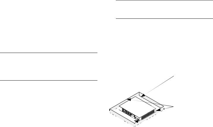
The following diagram shows recommended minimum clearances for adequate chassis airflow and access to components at the rear of the chassis—e.g., back up power supply and power switch(es).
Rear. 5 inches minimum at rear of chassis for installation and removal of optional back up power supply.
Sides. 2 inches minimum |
at left and right sides for |
chassis airflow. |
 Front. 6 inches minimum at front of chassis for cable access and LED visibility.
Chassis Top View
March 2005 |
Setting Up the Hardware 9 |

Never obstruct the air vents located at the left and right sides of the chassis.
Note. Clearance is not required at the top and bottom of the chassis. For detailed chassis airflow diagrams, refer to the Hardware Users Guide.
There are two ways in which the OmniSwitch 6600 Family can be installed:
•Tabletop installation
•Rack-mount installation
For information on setting up a switch as a tabletop unit, refer to “Installing the Switch on a Tabletop or Bench” on page 10. For information on rack-mounting the switch, refer to “Rack-Mounting the Switch” on page 11.
Installing the Switch on a Tabletop or Bench
OmniSwitch 6600 Family switches can be installed freestanding as tabletop units. Locate your switch in a stable, flat, staticfree surface.
Note. OmniSwitch 6600 Family switches must be placed “right side up.” Never attempt to operate a switch positioned on its side.
To install the switch as a tabletop unit, follow the steps below:
1Position the chassis on the table or bench where it is to be installed. Refer to page 7 for chassis weight considerations.
2Be sure that adequate clearance has been provided for chassis airflow and access to the front, back, and sides of the switch. For recommended clearances, refer to page 9. Also, be sure that you have placed the chassis within reach of all required AC power sources. For environmental and electrical requirements, refer to page 6.
3If you are placing multiple switches in a stacked configuration, carefully stack the remaining switches, one on top of the other. Up to eight switches may be stacked to form a single virtual chassis. Be sure to maintain adequate clearance at the front, rear, left, and right side of all switches.
4Verify that the on/off switch for each OmniSwitch 6600 Family is in the off ( O ) position.
10 Setting Up the Hardware |
March 2005 |

5 Plug the power cord (supplied) into the power socket located on the switch’s rear panel; next, plug the cord into an easily-accessible grounded AC power source. See “Electrical Requirements” on page 6 for more information.
Note. Do not turn on the power supplies at this time. You will power on all switches later in the setup process.
6 Continue to “Installing a Back Up Power Supply (OS6624, OS6648, OS6600-U24)” on page 14.
Rack-Mounting the Switch
Refer to the important guidelines below before installing the OmniSwitch chassis in a rack.
•It is recommended that two people install the switch in the rack—one person to hold the chassis and position it in the rack, and a second person to secure the chassis to the rack using attachment screws (not supplied).
•Alcatel provides two rack-mount flanges with each OmniSwitch 6600 Family switch. These flanges support standard 19-inch rack mount installations. These flanges must be attached to the chassis before the switch can be rack mounted.
Note. If you are installing the switch in a 23-inch wide rack, Alcatel offers optional 23-inch rack-mounting hardware. For more information, contact your Alcatel representative.
•Alcatel does not provide rack-mount screws. Use the screws supplied by the rack vendor.
•To prevent a rack from becoming top heavy, it is recommended that you install heavier equipment at the bottom of the rack whenever possible.
•If you are installing the switch in a relay rack, be sure to install and secure the rack per the rack manufacturer’s specifications.
•Review page 9 for important chassis airflow and access recommendations before installing.
To rack-mount the switch, follow the steps below.
1 Align the holes in the provided rack-mount flanges with the four threaded holes in the OmniSwitch chassis. These threaded holes are located in the left and right sides of the chassis, near the front panel.
March 2005 |
Setting Up the Hardware 11 |
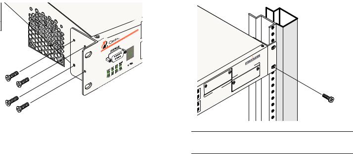
2 Attach the flanges to the chassis using the provided Phillips-head screws. Be sure to tighten each of the screws firmly using a Phillips screwdriver.
6 Once the holes are aligned, insert a rack mount screw (not provided) through the bottom hole of each flange. Tighten both screws until they are secure.
4 662
3After the rack-mount flanges are secured to the chassis, mark the holes on the rack where the switch is to be installed.
4Lift and position the switch until the rack-mount flanges are flush with the rack post.
5Align the holes in the flanges with the rack holes that were marked in step 3.
ACKING |
||
EXPANSION/ST |
5 |
2 |
|
|
|
5 1 |
|
|
50
4 |
|
EXPANSION |
7 |
|
|
|
9 |
|
8 |
|
|
Note. Be sure to install the screws in the bottom hole of each flange, as shown, before proceeding.
7Once the screws at the bottom of each flange are secure, install the remaining two rack mount screws. Be sure that all screws are securely tightened.
8On OS6624, OS6648, OS660-U24, and OS6600-P24 switches verify that the on/off switch for the OmniSwitch 6600 Family switch is in the off ( O ) position. The on/off switch is located on the switch’s rear panel.
12 Setting Up the Hardware |
March 2005 |

9 Plug the power cord (supplied) into the power socket located on the switch’s rear panel; next, plug the cord into an easily-accessible grounded AC power source. See “Electrical Requirements” on page 6 for more information.
Note. Do not turn on the power supply at this time. You will power on the switch later in the setup process.
10If you wish to install a supplemental ground for the switch, you may attach a type LCD8-10A-L grounding lug to the grounding lug, located on the switch’s rear panel. Install the type LCD8-10A-L grounding lug per manufacturer’s specifications.
11If you are installing multiple switches in a rack to form a stacked configuration, refer to “Rack Mounting Stacked Configurations” on page 13. If you are not installing a stacked configuration, continue to “Installing a Back Up Power Supply (OS6624, OS6648, OS6600-U24)” on page 14.
Rack Mounting Stacked Configurations
If you are rack mounting multiple switches in a stacked configuration, be sure to place all switches in verticallyadjacent rack positions. This will ensure that all required stacking cables will have adequate length for the installation. For additional instructions on rack mounting a stacked configuration, follow the steps below:
1Install the rack mount flanges for all switches that are to be included in the stacked configuration, as described on page 11. Up to eight switches may be stacked to form a single virtual chassis.
2Place the next switch in the stack directly on top of the previously installed switch.
3Align the holes in the flanges with the holes in the rack’s vertical posts.
4Once the holes are aligned, insert a rack mount screw through the bottom hole of each flange. Tighten both screws until they are secure. Once the screws at the bottom of each flange are secure, install the remaining two rack mount screws. Be sure that all screws are securely tightened.
5Repeat steps 1 through 4 above for all remaining switches.
6On OS6624, OS6648, OS660-U24, and OS6600-P24 switches verify that the on/off switch for each OmniSwitch 6600 Family switch is in the off ( O ) position.
March 2005 |
Setting Up the Hardware 13 |

7 Plug a power cord (supplied) into the power socket of each switch; next, plug each cord into an easily-accessible grounded AC power source.
Note. Do not turn on the power supplies at this time. You will power on all switches later in the setup process.
8If you wish to install a supplemental ground for each switch, you may attach a type LCD8-10A-L grounding lug to the grounding lug. Install the type LCD8-10A-L grounding lug per manufacturer’s specifications.
9After you have rack-mounted your switches, continue to “Installing a Back Up Power Supply (OS6624, OS6648, OS6600-U24)” on page 14.
Installing a Back Up Power Supply
(OS6624, OS6648, OS6600-U24)
If the optional back up power supply was included with your order, install the power supply now by following the steps below. The back up power supply bay is located at the switch’s rear panel.
Anti-Static Warning. Before handling any components, free yourself of static by wearing a grounding strap, or by grounding yourself properly. Static discharge can damage the switch and the back up power supply.
1 If there is a blank cover panel installed at the back up power supply bay, uninstall it by removing the two Phillips attachment screws. After the attachment screws have been removed, carefully pry the blank cover panel out and away from the chassis. Set the cover panel and attachment screws aside.
14 Setting Up the Hardware |
March 2005 |

2 To avoid attempting to install the power supply upside down, orient the unit as shown in the diagram below.
Top
|
|
|
|
|
|
|
|
|
|
/23 |
0 V |
A |
|
|
|
|
|
|
|
|
|
00/1 |
15 |
, |
2/2 |
|
|
|
|
|
|
|
|
PEDUCET |
1 |
Hz |
|
|
|
|
|
|
|
|
|
|
|
/60 |
|
|
|
|
|
||
|
|
|
|
|
UIPREDNEC |
50 |
|
|
|
|
|
|
|
|
|
|
|
BE EQ. TO |
ON |
|
|
|
|
|
|
|
|
|
|
|
MAYTIONS DISC |
|
|
|
|
|
|
|
|||
|
|
|
UNITNEC |
OCK, |
RE |
|
|
|
|
|
|
|
|
|
BO VIC |
THIS CONAL SHS BEFO |
|
RTEDE CHE |
|
|
|
|
|
Orient the back up power |
|||
|
W |
CETD'ALIM |
NTA |
|
|
|
|
|
|
||||
|
|
CT ECTION |
|
|
|
|
|
|
|
|
|||
|
|
ER RIC |
CO |
. A EBR |
D |
|
|
|
|
|
|
||
|
CAUTION:TW F CO |
|
|
|
|
|
|
||||||
|
|
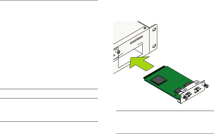
POELE NN |
MPO FIN AN |
E |
|
|
|
|
|
|
|||
|
ITH ISK |
ER . |
|
ION |
D ANTE |
|
|
|
|
|
|
|
|
|
W R W UNIT |
AREILTATUES, AV |
|
|
|
|
|
|
|
||||
! |
THETH POING |
|
APP ENRIQTION |
|
|
|
|
|
|
|
supply with the vent side |
||
PREVD LA REP |
ON S ELECT |
|
|
|
|
|
|
|
|
||||
|
SER |
|
|
|
|
|
|
|
|
|
|
||
|
ATTENTION:D'UN LE O ION |
|
|
|
|
|
|
|
|
|
|
||
|
|
RD |
CD'ALIM |
|
|
|
|
|
|
|
|
|
|
|
|
C S CHONS . |
|
|
|
|
|
|
|
|
|
|
|
|
SENIRCORD |
T |
|
|
|
|
|
|
|
|
|
|
|
|
PLU EUX |
ARA |
|
|
|
|
|
|
|
|
|
up, as shown. |
|
|
LESRE |
|
|
|
|
|
|
|
|
|
|
|
|
|
FAI |
|
|
|
|
|
|
|
|
|
|
|
|
3 Grasp the front portion of the power supply and carefully insert the rear of the casing into the power supply
bay. Slide the power supply back until the unit meets the connector in the chassis power supply bay.
|
|
|
|
|
|
|
|
|
AD |
s |
|
|
|
|
|
|
|
LEU |
|
U CAN |
|
|
|
|
|
|
|
|
R D |
Component |
|
|
|
|
|
|
BR |
OUIL |
|
-US |
|
|
|
|
|
|
|
an |
d Non |
|
|
|
||
|
É |
RIEL |
|
|
|
|
|
|||
|
of US |
|
|
|
|
|
|
|||
|
|
US |
|
|
|
|
|
|
||
the
|
|
|
|
|
|
|
|
|
|
|
|
V A |
|
|
|
|
|
|
|
|
|
|
|
|
100/115/230Hz, |
|
|
|
|
|
|
|
|
|
|
|
|
2/2/1 |
|
|
|
|
|
|
|
|
|
EQUIPPEDREDUCE |
50/60 |
||
|
|
|
|
|
|
|
|
|
BE |
. TOCONNECT |
|
|
|
|
|
|
|
|
|
|
MAYCTIONS |
DIS |
|
|
|
|
|
|
|
: |
|
|
UNIT SHOCK,BEFORE |
|
|
|||
|
|
|
|
THIS CONNE |
S |
|
|
|
||||
|
|
|
TIO POWERELECTRICAL |
COMPORTE. AFIN |
DE |
|
||||||
|
|
AUTWO |
|
CONNECTION |
|
|||||||
|
|
|
N |
|
|
|
|
|
|
DE |
|
|
|
C |
|
OF . |
APP |
|
ON DEBRANCHE |
|
|||||
|
THE |
POWERUNIT |
|
ON |
|
|
||||||
|
WITHRISK |
|
|
|
|
AREILATI |
AVANTE |
|
|
|||
|
BOTH |
|
|
|
: |
CETD'ALIMENTCTRIQUES,ATI |
|
|
||||
|
SERVICINGION |
|
N |
ELE |
|
|
|
|
||||
|
|
E |
NT CORDOCHOCSD'ALIMENT |
|
|
|
||||||
|
|
|
|
S |
|
NS . |
|
|
|
|
|
|
|
ATT D'UN LERDO |
|
|
|
|
|
||||||
! |
PLUS |
COARATION |
|
|
|
|
|
|||||
PREVENIRDEUXREP |
|
|
|
|
|
|
|
|
||||
LES |
LA |
|
|
|
|
|
|
|
|
|
||
|
FAIRE |
|
|
|
|
|
|
|
|
|
|
|
! |
4 Continue sliding the power supply back until the front panel is flush with the rear panel of the chassis. Do not force the power supply into the bay. Otherwise you can damage the connectors.
March 2005 |
Setting Up the Hardware 15 |
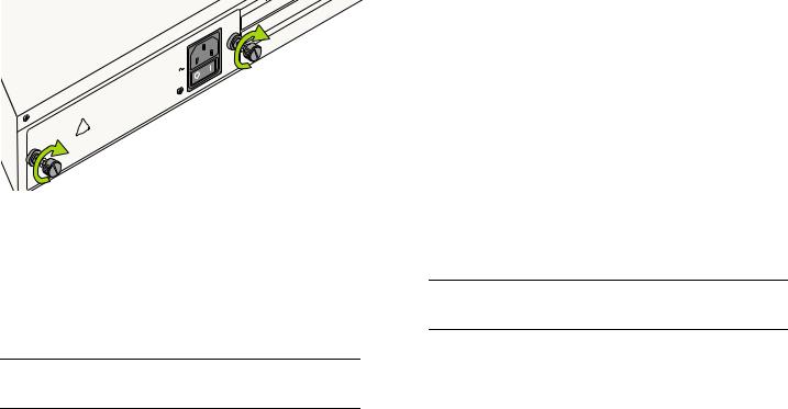
5 Tighten the two captive screws, located at the left and right sides of the power supply’s front panel. Be sure not to overtighten the captive screws. If you use a screwdriver, the torque used to tighten the screws must not exceed 2.3 inch pounds.
!
|
|
|
|
|
EQUIPPREDUCE |
||
|
|
|
|
Y BE . |
TO |
NNECT |
|
|
|
|
|
DISCO |
|||
|
|
|
|
MA |
|
||
|
|
|
|
CTIONS |
|
|
|
|
|
|
UNIT SHOCK,BEFORE |
|
|||
|
|
THIS CONNEL |
S |
|
|
||
|
POWERELECTRICA |
|
|
TE |
|||
|
TWO |
CONNECTION |
COMPOR. AFIN |
||||
CAUTION:OF |
. |
APP |
|
ON |
DEBRANCHETE |
||
THE |
POWERUNIT |
|
|
AVAN |
|||
WITHRISK |
|
|
AREILATI |
|
|||
BOTHVICING |
|
CETD'ALIMENTECTRIQUES, |
|
||||
|
|
|
|
|
ATION |
|
|
|
NTION:CO CHOCSD'ALIMENT |
|
|
||||
SER |
|
RDON |
EL |
|
|
|
|
|
|
S |
NS . |
|
|
|
|
ATTED'UN LERDOTION |
|
|
|
|
|||
PREVENIRDEUXREP |
|
|
|
|
|
|
|
PLUS |
COARA |
|
|
|
|
||
LES |
LA |
|
|
|
|
|
|
FAIRE |
|
|
|
|
|
|
|
|
|
|
100 |
OS0V |
|
ITH G HAR ERRED |
|
IR |
LAT |
|
LES |
AD |
|
||||||
|
|
|
|
MPLIESFOLLOWINCAUSE |
UNDESIALL |
|
|
TOU |
TS |
CAN |
|
s |
|||||||
|
|
NO: |
- |
24 |
|
|
|
|
|
INT |
REQUREGU |
|
|
||||||
|
|
|
|
|
|
|
ANY |
|
|
DU |
|
|
|||||||
MODEL |
CO |
|
NOT |
|
|
MEETSEQUIPMENT |
|
|
US |
Component |
|
||||||||
TO |
THEY |
|
ACCEPTCAUSE |
|
on- |
|
|
|
|||||||||||
|
|
|
|
MA |
|
M |
AY |
|
|
|
|
|
|
|
|||||
RATING:DEVICE |
|
MUST |
|
|
ATUS |
A RESPECTEBROUILLEURN |
|
|
|
||||||||||
|
|
|
|
|
|
|
|
|
|
and |
|
|
|
|
|
||||
THISSUBJECTDEVICE THA |
|
|
PARCAUSING |
SSE RIEL US |
|
|
|
|
|
|
|||||||||
IS |
THIS |
DEVICE |
|
|
|
AP |
- |
LA |
CLA |
of |
|
|
|
|
|
|
|||
INTERFERENCE |
|
|
RIQUE |
DE |
LE |
the |
|
|
|
|
|
|
|
||||||
(1) THIS |
|
|
IGITALENCE |
|
|
|
|
|
|
|
|
||||||||
(2) |
|
|
A D |
|
FER |
|
|
|
SUR |
in |
|
|
|
|
|
|
|
|
|
|
CLASSINTER |
|
|
Assembled |
|
|
|
|
|
|
|
|
|||||||
THIS |
|
NUMÉ |
|
|
|
|
|
|
|
|
|
|
|||||||
|
|
REGLEMENT |
|
|
|
|
|
|
|
|
|
||||||||
CANADIAN |
DU |
|
|
|
|
|
|
|
|
|
|
|
|
|
|
|
|
||
|
APPAREIL |
|
|
|
|
|
|
|
|
|
|
|
|
|
|
|
|
||
EXIGENCES |
|
|
|
|
|
|
|
|
|
|
|
|
|
|
|
|
|||
CET |
|
|
|
|
|
|
|
|
|
|
|
|
|
|
|
|
|
|
|
V A 100/115/230Hz, 2/2/1 50/60
6On OS6624, OS6648, OS660-U24, and OS6600-P24 switches verify that the power supply’s on/off switch is in the off ( O ) position.
7Plug a power cord (supplied) into the unit’s power socket; next, plug the cord into an easily-accessible, grounded power source.
Note. Do not turn on the power supply at this time. You will power on all supplies later in the setup process.
8If you are installing back up power supplies in a multichassis, stacked configuration, install all remaining power supply units now by repeating steps 1 through 7 for each chassis.
9Continue to “Installing Uplink and Stacking Modules” on page 16.
Installing Uplink and Stacking
Modules
OmniSwitch 6600 Family switches support the following modules:
•OS6600-GNI-C2 Copper Gigabit Ethernet Uplink Module
•OS6600-GNI-U2 Fiber Gigabit Ethernet Uplink Module
•Stacking Module
Note. This section does not apply to OS6602-24 and OS6602-48 switches.
16 Setting Up the Hardware |
March 2005 |
If uplink modules and/or stacking kits were specified with your order, install them now by following the steps below:
Important. Stacking modules can only be installed in the far-right module slot. This slot is labeled EXPANSION/ STACKING and contains port positions 27 and 28 (OS6624 and OS6600-U24) or 51 and 52 (OS6648).
Do not attempt to install stacking modules at the EXPANSION slot at port positions 25 and 26 (OS6624 and OS6600-U24) or 49 and 50 (OS6648).
OS6600-GNI-U2 and OS6600-GNI-C2 uplink modules can be installed in either slot location. However, if you install a Gigabit Ethernet uplink module in the EXPANSION/STACKING slot, the switch must be used as a stand-alone unit.
Port numbers are clearly marked on the OmniSwitch 6600 Family chassis front panels.
Anti-Static Warning. Before handling any components, free yourself of static by wearing a grounding strap, or by grounding yourself properly. Static discharge can damage the switch and the uplink or stacking module.
1 If there is a blank cover panel installed over the uplink or stacking module slot position, uninstall it by removing the two Phillips attachment screws. After the attachment
screws have been removed, carefully pry the blank cover panel out and away from the chassis. Set the cover panel and attachment screws aside.
2 Holding the uplink or stacking module by the front panel, carefully slide the circuit board into the card guide located in the chassis slot.
ACKING |
||
EXPANSION/ST |
5 |
2 |
|
|
|
5 1 |
|
|
 LINK/ACT
LINK/ACT
Note. The module should slide in easily. Do not force the module into the slot. If any resistance is encountered, ensure that the module is aligned properly in the card guide and try again.
March 2005 |
Setting Up the Hardware 17 |
Loading...