


ALCATEL OMNIPCX OFFICE
REF: 3EH21017BSAA Ed. 02

ALCATEL OMNIPCX
OFFICE
REF: 3EH21017BSAA Ed. 02
Copyright © ALCATEL. 2000. All rights reserved. Alcatel Business Systems, in keeping with its policy of constant product improvement for the customer, reserves the right to modify product specifications without prior notice.
GENERAL INDEX
Section
INSTALLATION MANUAL

Alcatel OmniPCX Office
GENERAL INDEX |
REF: 3EH21017BSAA Ed. 02 |

ALCATEL OMNIPCX OFFICE
GENERAL INDEX
General Index
Symbols
'Please Wait' message
– Presentation of boards . . . . . . . . . . . . . . . . . . . . . . . . . . . . . . . . . . . . . . File 4 p. 4 “Please wait” message
– Connection . . . . . . . . . . . . . . . . . . . . . . . . . . . . . . . . . . . . . . . . . . . . . . File 6 p. 16
– CPU boards . . . . . . . . . . . . . . . . . . . . . . . . . . . . . . . . . . . . . . . . . . . . . . File 6 p. 5
A
Alarm
– Connection . . . . . . . . . . . . . . . . . . . . . . . . . . . . . . . . . . . . . . . . . . . . . . File 6 p. 17
– CPU boards . . . . . . . . . . . . . . . . . . . . . . . . . . . . . . . . . . . . . . . . . . . . . . File 6 p. 5
– Presentation of boards . . . . . . . . . . . . . . . . . . . . . . . . . . . . . . . . . . . . . . File 4 p. 4 Alcatel Reflexes terminals
– Connecting . . . . . . . . . . . . . . . . . . . . . . . . . . . . . . . . . . . . . . . . . . . . . . File 6 p. 11
– Powering on . . . . . . . . . . . . . . . . . . . . . . . . . . . . . . . . . . . . . . . . . . . . . . File 6 p. 22
– UAI board . . . . . . . . . . . . . . . . . . . . . . . . . . . . . . . . . . . . . . . . . . . . . . . File 6 p. 6 Analog terminals
– Connecting . . . . . . . . . . . . . . . . . . . . . . . . . . . . . . . . . . . . . . . . . . . . . . File 6 p. 11
– Doorphone . . . . . . . . . . . . . . . . . . . . . . . . . . . . . . . . . . . . . . . . . . . . . . File 6 p. 20
– MIX X/Y/Z boards . . . . . . . . . . . . . . . . . . . . . . . . . . . . . . . . . . . . . . . . . . File 4 p. 8
– Replacing . . . . . . . . . . . . . . . . . . . . . . . . . . . . . . . . . . . . . . . . . . . . . . . . File 15 p. 1
– SLI board . . . . . . . . . . . . . . . . . . . . . . . . . . . . . . . . . . . . . . . . . . . . . . . . File 6 p. 6
– SLI-X boards . . . . . . . . . . . . . . . . . . . . . . . . . . . . . . . . . . . . . . . . . . . . . . File 4 p. 8
– Software key. . . . . . . . . . . . . . . . . . . . . . . . . . . . . . . . . . . . . . . . . . . . . . File 5 p. 3
B
Background music
– Connection . . . . . . . . . . . . . . . . . . . . . . . . . . . . . . . . . . . . . . . . . . . . . . File 6 p. 17
– CPU boards . . . . . . . . . . . . . . . . . . . . . . . . . . . . . . . . . . . . . . . . . . . . . . File 6 p. 5
– Software key. . . . . . . . . . . . . . . . . . . . . . . . . . . . . . . . . . . . . . . . . . . . . . File 5 p. 4 Base stations . . . . . . . . . . . . . . . . . . . . . . . . . . . . . . . . . . . . . . . . . . . . . . . . File 8 p. 2 Batteries
– Characteristics . . . . . . . . . . . . . . . . . . . . . . . . . . . . . . . . . . . . . . . . . . . . File 16 p. 1
– Maintenance . . . . . . . . . . . . . . . . . . . . . . . . . . . . . . . . . . . . . . . . . . . . . File 16 p. 1
– Recommendations . . . . . . . . . . . . . . . . . . . . . . . . . . . . . . . . . . . . . . . . . File 3 p. 1
– Replacing . . . . . . . . . . . . . . . . . . . . . . . . . . . . . . . . . . . . . . . . . . . . . . . . File 6 p. 21
Ed. 02 |
Ref. 3EH 21017 BSAA |
1/6 |

ALCATEL OMNIPCX OFFICE
GENERAL INDEX
Battery maintenance . . . . . . . . . . . . . . . . . . . . . . . . . . . . . . . . . . . . . . . . . . . File 16 p. 1
C
Cables. . . . . . . . . . . . . . . . . . . . . . . . . . . . . . . . . . . . . . . . . . . . . . . . . . . . . |
File 6 p. 7 |
|
Configuration |
|
|
– |
Fast IP Reflexes . . . . . . . . . . . . . . . . . . . . . . . . . . . . . . . . . . . . . . . . . . . . |
File 9 p. 1 |
– |
Network . . . . . . . . . . . . . . . . . . . . . . . . . . . . . . . . . . . . . . . . . . . . . . . . . |
File 10 p. 1 |
– |
PC . . . . . . . . . . . . . . . . . . . . . . . . . . . . . . . . . . . . . . . . . . . . . . . . . . . . . |
File 13 p. 1 |
– |
Web browser . . . . . . . . . . . . . . . . . . . . . . . . . . . . . . . . . . . . . . . . . . . . . |
File 10 p. 1 |
Connecting |
File 6 p. 16 |
|
– |
Auxiliary equipment. . . . . . . . . . . . . . . . . . . . . . . . . . . . . . . . . . . . . . . . . |
|
– |
CPU boards . . . . . . . . . . . . . . . . . . . . . . . . . . . . . . . . . . . . . . . . . . . . . . |
File 6 p. 8 |
– |
Lan . . . . . . . . . . . . . . . . . . . . . . . . . . . . . . . . . . . . . . . . . . . . . . . . . . . . |
File 6 p. 15 |
– |
Terminals . . . . . . . . . . . . . . . . . . . . . . . . . . . . . . . . . . . . . . . . . . . . . . . . |
File 6 p. 11 |
Connection |
|
|
– |
Boards . . . . . . . . . . . . . . . . . . . . . . . . . . . . . . . . . . . . . . . . . . . . . . . . . . |
File 4 p. 4 |
– |
DECT base stations . . . . . . . . . . . . . . . . . . . . . . . . . . . . . . . . . . . . . . . . . |
File 8 p. 1 |
– |
e-Reflexes . . . . . . . . . . . . . . . . . . . . . . . . . . . . . . . . . . . . . . . . . . . . . . . . |
File 9 p. 1 |
– |
mains . . . . . . . . . . . . . . . . . . . . . . . . . . . . . . . . . . . . . . . . . . . . . . . . . . . |
File 6 p. 22 |
– |
UPS . . . . . . . . . . . . . . . . . . . . . . . . . . . . . . . . . . . . . . . . . . . . . . . . . . . . |
File 6 p. 21 |
CPU-CPUe Boards |
|
|
– |
Changing . . . . . . . . . . . . . . . . . . . . . . . . . . . . . . . . . . . . . . . . . . . . . . . . |
File 16 p. 3 |
D
DECT base station
– ARI number . . . . . . . . . . . . . . . . . . . . . . . . . . . . . . . . . . . . . . . . . . . . . . File 12 p. 6 DECT Base Stations
– Installation . . . . . . . . . . . . . . . . . . . . . . . . . . . . . . . . . . . . . . . . . . . . . . . File 8 p. 1 DECT base stations
– Positioning . . . . . . . . . . . . . . . . . . . . . . . . . . . . . . . . . . . . . . . . . . . . . . . File 8 p. 3 DNS . . . . . . . . . . . . . . . . . . . . . . . . . . . . . . . . . . . . . . . . . . . . . . . . . . . . . . File 14 p. 5 Doorphone
– Connection . . . . . . . . . . . . . . . . . . . . . . . . . . . . . . . . . . . . . . . . . . . . . . . File 6 p. 19
– CPU boards . . . . . . . . . . . . . . . . . . . . . . . . . . . . . . . . . . . . . . . . . . . . . . File 6 p. 5
– Presentation of boards. . . . . . . . . . . . . . . . . . . . . . . . . . . . . . . . . . . . . . . File 4 p. 4
E
Easy View. . . . . . . . . . . . . . . . . . . . . . . . . . . . . . . . . . . . . . . . . . . . . . . . . . . File 13 p. 1 EasyPlus View. . . . . . . . . . . . . . . . . . . . . . . . . . . . . . . . . . . . . . . . . . . . . . . . File 13 p. 1 Expert View . . . . . . . . . . . . . . . . . . . . . . . . . . . . . . . . . . . . . . . . . . . . . . . . . File 13 p. 1 Extension module
– Adding . . . . . . . . . . . . . . . . . . . . . . . . . . . . . . . . . . . . . . . . . . . . . . . . . . File 15 p. 6
– Presentation of boards. . . . . . . . . . . . . . . . . . . . . . . . . . . . . . . . . . . . . . . File 4 p. 4 Extension unit
– Transfer . . . . . . . . . . . . . . . . . . . . . . . . . . . . . . . . . . . . . . . . . . . . . . . . . File 15 p. 2 Extension units
2/6 |
Ref. 3EH 21017 BSAA |
Ed. 02 |

ALCATEL OMNIPCX OFFICE
GENERAL INDEX
– |
Adding. . . . . . . . . . . . . . . . . . . . . . . . . . . . . . . . . . . . . . . . . . . . . . . . . . |
File 7 p. 3 |
External loudspeaker |
|
|
– |
Connection . . . . . . . . . . . . . . . . . . . . . . . . . . . . . . . . . . . . . . . . . . . . . . |
File 6 p. 18 |
– |
CPU boards . . . . . . . . . . . . . . . . . . . . . . . . . . . . . . . . . . . . . . . . . . . . . . |
File 6 p. 5 |
G
General bell |
File 4 p. 4 |
|
– |
Presentation of boards . . . . . . . . . . . . . . . . . . . . . . . . . . . . . . . . . . . . . . |
|
General call ringer |
|
|
– |
CPU boards . . . . . . . . . . . . . . . . . . . . . . . . . . . . . . . . . . . . . . . . . . . . . . |
File 6 p. 5 |
General ringer |
File 6 p. 18 |
|
– |
Connection . . . . . . . . . . . . . . . . . . . . . . . . . . . . . . . . . . . . . . . . . . . . . . |
|
H
Hard disk |
|
|
– |
Maintenance . . . . . . . . . . . . . . . . . . . . . . . . . . . . . . . . . . . . . . . . . . . . . |
File 16 p. 4 |
Hardware |
File 4 p. 1 |
|
– |
Reception . . . . . . . . . . . . . . . . . . . . . . . . . . . . . . . . . . . . . . . . . . . . . . . . |
|
– |
Vibrations. . . . . . . . . . . . . . . . . . . . . . . . . . . . . . . . . . . . . . . . . . . . . . . . |
File 6 p. 3 |
I
Installation synopsis . . . . . . . . . . . . . . . . . . . . . . . . . . . . . . . . . . . . . . . . . . . |
File 4 p. 3 |
|
Interfaces |
File 3 p. 2 |
|
– |
Classification . . . . . . . . . . . . . . . . . . . . . . . . . . . . . . . . . . . . . . . . . . . . . |
|
Internet |
|
|
– |
Access . . . . . . . . . . . . . . . . . . . . . . . . . . . . . . . . . . . . . . . . . . . . . . . . . . |
File 14 p. 1 |
– |
Boards . . . . . . . . . . . . . . . . . . . . . . . . . . . . . . . . . . . . . . . . . . . . . . . . . . |
File 4 p. 7 |
– |
Client PCs . . . . . . . . . . . . . . . . . . . . . . . . . . . . . . . . . . . . . . . . . . . . . . . |
File 10 p. 1 |
– |
Connection test. . . . . . . . . . . . . . . . . . . . . . . . . . . . . . . . . . . . . . . . . . . . |
File 14 p. 7 |
– |
Software key. . . . . . . . . . . . . . . . . . . . . . . . . . . . . . . . . . . . . . . . . . . . . . |
File 5 p. 3 |
– |
Subscription . . . . . . . . . . . . . . . . . . . . . . . . . . . . . . . . . . . . . . . . . . . . . . |
File 14 p. 2 |
L
LAN |
|
|
– |
Internet . . . . . . . . . . . . . . . . . . . . . . . . . . . . . . . . . . . . . . . . . . . . . . . . . |
File 14 p. 1 |
– |
LAN boards . . . . . . . . . . . . . . . . . . . . . . . . . . . . . . . . . . . . . . . . . . . . . . |
File 4 p. 10 |
– |
LEDs . . . . . . . . . . . . . . . . . . . . . . . . . . . . . . . . . . . . . . . . . . . . . . . . . . . |
File 4 p. 6, 7 |
– |
Software key. . . . . . . . . . . . . . . . . . . . . . . . . . . . . . . . . . . . . . . . . . . . . . |
File 5 p. 3 |
LEDs |
File 4 p. 6, 7 |
|
– |
Function . . . . . . . . . . . . . . . . . . . . . . . . . . . . . . . . . . . . . . . . . . . . . . . . . |
|
Loudspeaker |
|
|
– |
Presentation of boards . . . . . . . . . . . . . . . . . . . . . . . . . . . . . . . . . . . . . . |
File 4 p. 4 |
Ed. 02 |
Ref. 3EH 21017 BSAA |
3/6 |

ALCATEL OMNIPCX OFFICE
GENERAL INDEX
M
Microswitches. . . . . . . . . . . . . . . . . . . . . . . . . . . . . . . . . . . . . . . . . . . . . . . . File 4 p. 6, 7 Module
– Racks . . . . . . . . . . . . . . . . . . . . . . . . . . . . . . . . . . . . . . . . . . . . . . . . . . . File 4 p. 2, 12 Multi Reflexes
– DECT base stations . . . . . . . . . . . . . . . . . . . . . . . . . . . . . . . . . . . . . . . . . File 15 p. 3
– Use . . . . . . . . . . . . . . . . . . . . . . . . . . . . . . . . . . . . . . . . . . . . . . . . . . . . File 15 p. 3 music player
– Presentation of boards. . . . . . . . . . . . . . . . . . . . . . . . . . . . . . . . . . . . . . . File 4 p. 4
P
PM5 |
File 9 p. 2 |
|
– |
Fast IP Reflexes . . . . . . . . . . . . . . . . . . . . . . . . . . . . . . . . . . . . . . . . . . . . |
|
– |
Features . . . . . . . . . . . . . . . . . . . . . . . . . . . . . . . . . . . . . . . . . . . . . . . . . |
File 13 p. 4 |
– |
Installation . . . . . . . . . . . . . . . . . . . . . . . . . . . . . . . . . . . . . . . . . . . . . . . |
File 13 p. 4 |
– |
loading software key . . . . . . . . . . . . . . . . . . . . . . . . . . . . . . . . . . . . . . . . |
File 16 p. 3 |
– |
Saving . . . . . . . . . . . . . . . . . . . . . . . . . . . . . . . . . . . . . . . . . . . . . . . . . . |
File 15 p. 4 |
– |
Software key . . . . . . . . . . . . . . . . . . . . . . . . . . . . . . . . . . . . . . . . . . . . . . |
File 5 p. 2 |
– |
Startup . . . . . . . . . . . . . . . . . . . . . . . . . . . . . . . . . . . . . . . . . . . . . . . . . . |
File 13 p. 1 |
R
Recommendations |
File 3 p. 1 |
|
– |
Conformity . . . . . . . . . . . . . . . . . . . . . . . . . . . . . . . . . . . . . . . . . . . . . . . |
|
– |
DECT . . . . . . . . . . . . . . . . . . . . . . . . . . . . . . . . . . . . . . . . . . . . . . . . . . . |
File 8 p. 3 |
– |
Directives . . . . . . . . . . . . . . . . . . . . . . . . . . . . . . . . . . . . . . . . . . . . . . . . |
File 3 p. 2 |
– |
Earthing . . . . . . . . . . . . . . . . . . . . . . . . . . . . . . . . . . . . . . . . . . . . . . . . . |
File 6 p. 22 |
– |
Environmental protection . . . . . . . . . . . . . . . . . . . . . . . . . . . . . . . . . . . . . |
File 8 p. 4 |
– |
Environments . . . . . . . . . . . . . . . . . . . . . . . . . . . . . . . . . . . . . . . . . . . . . |
File 6 p. 3 |
– |
General . . . . . . . . . . . . . . . . . . . . . . . . . . . . . . . . . . . . . . . . . . . . . . . . . |
File 3 p. 1 |
– |
Site. . . . . . . . . . . . . . . . . . . . . . . . . . . . . . . . . . . . . . . . . . . . . . . . . . . . . |
File 6 p. 3 |
Reflexes terminals |
File 15 p. 4 |
|
– |
Adding . . . . . . . . . . . . . . . . . . . . . . . . . . . . . . . . . . . . . . . . . . . . . . . . . . |
|
– |
Advanced terminals. . . . . . . . . . . . . . . . . . . . . . . . . . . . . . . . . . . . . . . . . |
File 12 p. 1 |
– |
Display . . . . . . . . . . . . . . . . . . . . . . . . . . . . . . . . . . . . . . . . . . . . . . . . . . |
File 12 p. 1 |
– Fastening First and Easy terminals . . . . . . . . . . . . . . . . . . . . . . . . . . . . . . |
File 7 p. 5 |
|
– First and Easy terminals . . . . . . . . . . . . . . . . . . . . . . . . . . . . . . . . . . . . . . |
File 11 p. 2 |
|
– |
Installation . . . . . . . . . . . . . . . . . . . . . . . . . . . . . . . . . . . . . . . . . . . . . . . |
File 7 p. 1 |
– Installing Premium and Advanced terminals . . . . . . . . . . . . . . . . . . . . . . . |
File 7 p. 1 |
|
– |
Moving . . . . . . . . . . . . . . . . . . . . . . . . . . . . . . . . . . . . . . . . . . . . . . . . . . |
File 15 p. 2 |
– Premium and Advanced terminals . . . . . . . . . . . . . . . . . . . . . . . . . . . . . . |
File 11 p. 1, 2 |
|
– |
Presentation of boards. . . . . . . . . . . . . . . . . . . . . . . . . . . . . . . . . . . . . . . |
File 4 p. 4 |
– |
Profile. . . . . . . . . . . . . . . . . . . . . . . . . . . . . . . . . . . . . . . . . . . . . . . . . . . |
File 11 p. 1 |
– |
Replacing . . . . . . . . . . . . . . . . . . . . . . . . . . . . . . . . . . . . . . . . . . . . . . . . |
File 15 p. 1 |
– |
Soft keys . . . . . . . . . . . . . . . . . . . . . . . . . . . . . . . . . . . . . . . . . . . . . . . . . |
File 12 p. 1 |
– |
Software key . . . . . . . . . . . . . . . . . . . . . . . . . . . . . . . . . . . . . . . . . . . . . . |
File 5 p. 3 |
4/6 |
Ref. 3EH 21017 BSAA |
Ed. 02 |
ALCATEL OMNIPCX OFFICE
GENERAL INDEX
– UAI-X boards . . . . . . . . . . . . . . . . . . . . . . . . . . . . . . . . . . . . . . . . . . . . . File 4 p. 8
S
Software key
– Changing. . . . . . . . . . . . . . . . . . . . . . . . . . . . . . . . . . . . . . . . . . . . . . . . File 5 p. 2
– Hardware reception . . . . . . . . . . . . . . . . . . . . . . . . . . . . . . . . . . . . . . . . File 4 p. 1
– Services controlled . . . . . . . . . . . . . . . . . . . . . . . . . . . . . . . . . . . . . . . . . File 5 p. 3
– Wizard . . . . . . . . . . . . . . . . . . . . . . . . . . . . . . . . . . . . . . . . . . . . . . . . . . File 13 p. 6 Software keys
– Definition . . . . . . . . . . . . . . . . . . . . . . . . . . . . . . . . . . . . . . . . . . . . . . . . File 5 p. 1
U
Using batteries. . . . . . . . . . . . . . . . . . . . . . . . . . . . . . . . . . . . . . . . . . . . . . . File 6 p. 21
V
Ventilation system
– Maintenance . . . . . . . . . . . . . . . . . . . . . . . . . . . . . . . . . . . . . . . . . . . . . File 16 p. 1
Ed. 02 |
Ref. 3EH 21017 BSAA |
5/6 |

ALCATEL OMNIPCX OFFICE
GENERAL INDEX
6/6 |
Ref. 3EH 21017 BSAA |
Ed. 02 |

Alcatel OmniPCX Office
SECTION |
INSTALLATION MANUAL |
REF: 3EH21017BSAA Ed. 02 |

ALCATEL OMNIPCX OFFICE
INSTALLATION MANUAL
Section Installation manual
REASONS FOR CHANGING ISSUE
SYMBOLS USED IN THIS MANUAL
SAFETY
PRESENTATION OF THE HARDWARE
SOFTWARE KEYS
INSTALLATION / WIRING
INSTALLING REFLEXES TERMINALS
INSTALLING DECT BASE STATIONS
INSTALLING FAST IP REFLEXES TERMINALS
INSTALLING CLIENT PCS
DEFAULT CONFIGURATION
STARTING UP THE SYSTEM FROM AN ADVANCED TERMINAL STARTING UP THE SYSTEM WITH PM5
INSTALLATION OF AN INTERNET ACCESS
UPGRADING YOUR SYSTEM
FIRST-LEVEL MAINTENANCE
GLOSSARY
FILE 1 FILE 2 FILE 3 FILE 4 FILE 5 FILE 6 FILE 7 FILE 8 FILE 9 FILE 10 FILE 11 FILE 12 FILE 13 FILE 14 FILE 15 FILE 16 FILE 17
Ed. 02 |
Réf. 3EH21017BSAA |
1/2 |

ALCATEL OMNIPCX OFFICE
SECTION INSTALLATION MANUAL INSTALLATION MANUAL (INDEX)
Section Installation manual (Index)
DEFAULT CONFIGURATION
FIRST-LEVEL MAINTENANCE
GLOSSARY
INSTALLATION / WIRING
INSTALLATION OF AN INTERNET ACCESS
INSTALLING CLIENT PCS
INSTALLING DECT BASE STATIONS
INSTALLING FAST IP REFLEXES TERMINALS
INSTALLING REFLEXES TERMINALS
PRESENTATION OF THE HARDWARE
REASONS FOR CHANGING ISSUE
SAFETY
SOFTWARE KEYS
STARTING UP THE SYSTEM FROM AN ADVANCED TERMINAL STARTING UP THE SYSTEM WITH PM5
SYMBOLS USED IN THIS MANUAL
UPGRADING YOUR SYSTEM
FILE 11 FILE 16 FILE 17 FILE 6 FILE 14 FILE 10 FILE 8 FILE 9 FILE 7 FILE 4 FILE 1 FILE 3 FILE 5 FILE 12 FILE 13 FILE 2 FILE 15
2/2 |
Réf. 3EH21017BSAA |
Ed. 02 |

|
|
|
INSTALLATION MANUAL |
REASONS FOR CHANGING ISSUE |
|
|
|
|
REASONS FOR CHANGING ISSUE
File
1
In relation to issue 01 of the manual, this issue adds the following changes:
-Sheet 4 "Hardware description": change in consumption for each model.
-Sheet 6 "Installation/Cabling":
•adds the description of how to attach Rack1 and Rack 2 models to the wall.
•details on recommendations for choice of site.
•modification of characteristics of relay contacts used to connect auxiliary equipment.
•modification of the characteristics of the battery fuse.
•deletion of consumption.
- modification of length of system downtime.
-Sheet 14 "Installation of Internet access": add procedures for connection by DSL modem and LAN to LAN routing
-Sheet 16 "First level maintenance": add recommendations on battery and cell maintenance.
Ed. 02 |
Réf. 3EH21017BSAA |
1/2 |

REASONS FOR CHANGING ISSUE |
|
INSTALLATION MANUAL |
|
||
|
|
|
2/2 |
Réf. 3EH21017BSAA |
Ed. 02 |

|
|
|
INSTALLATION MANUAL |
SYMBOLS USED IN THIS MANUAL |
|
|
|
|
SYMBOLS USED IN THIS MANUAL
File
2
Indicates a remark.
Indicates important information.
Ed. 02 |
Réf. 3EH21017BSAA |
1/2 |

SYMBOLS USED IN THIS MANUAL |
|
INSTALLATION MANUAL |
|
||
|
|
|
2/2 |
Réf. 3EH21017BSAA |
Ed. 02 |
INSTALLATION MANUAL |
|
SAFETY |
|
||
|
|
|
SAFETY
DECLARATION OF CONFORMITY
File
3
We,
Alcatel Business Systems 32, avenue Kléber
92707 Colombes Cedex - France
declare that the following products are deemed to comply with the requirements of Directive 1999/ CE/5 of the European Parliament and the Council.
Any unauthorized modification of the products makes this declaration of conformity null and void.
Pursuant to the directive, as published in the Official Journal of the European Community of April 7, 1999, these appliances can be used in all the countries of the European Community, Switzerland and Norway.
© Alcatel Business Systems 2001. All rights reserved. Alcatel Business Systems, in keeping with its policy of constant product improvement for the customer, reserves the right to modify product specifications without prior notice.
Alcatel Business Systems - 32, avenue Kléber F-92707 Colombes Cedex RCS Paris 602 033 185.
GENERAL RECOMMENDATIONS
It is vitally important to connect this product to a permanent ground connection installed in accordance with the rules of the art.
Owing to the presence of hazardous voltages, the metal back plate may only be removed by suitably qualified personnel.
In the event of a poor earth connection, it is IMPERATIVE to disconnect the telecommunications ports before reconnecting the earth. A check must then be made to ensure that all the connections have been made correctly.
If it is necessary to intervene in the power supply unit, disconnect the mains cable before removing the metal panel on the power supply unit and disconnect the batteries.
Ed. 02 |
Réf. 3EH21017BSAA |
1/2 |
SAFETY |
|
INSTALLATION MANUAL |
|
DECLARATION OF CONFORMITY WITH DIRECTIVES
This appliance is designed to be connected to the public telephone network through appropriate interfaces.
The CE marking indicates that the product complies with prevailing community directives, in particular:
-89/336/CEE (Electromagnetic compatibility)
-73/23/CEE (Low voltage)
-1999/5/CE (R&TTE)
CLASSIFICATION OF INTERFACES
SELV: Safety Extra Low Voltage
TNV-3: Telecommunications Network Voltage
Alcatel
OmniPCX
Office
|
Reflexes |
|
|
4070 base station |
|
UAI |
|
SELV |
|
||
Mains power
PS
|
Z station |
|
SLI |
|
TNV-3 |
|
||
|
HSL |
|
CPU |
|
SELV |
|
||
|
|
|
|
12 V/300 mA |
SELV |
|
|
ISDN |
|
|
Audio In/Out |
||
|
|
|
SELV |
|||
|
BRA |
|
|
|||
SELV |
CPU |
Management |
||||
|
|
|||||
|
PRA |
SELV |
||||
|
||||||
|
|
|
|
|||
|
|
|
V24/MMC |
|||
|
|
|
|
SELV |
||
|
|
|
|
|
||
|
|
|
|
|
TL
TNV-3 |
|
ATA |
Ethernet |
|
|
||||
|
|
|
||
|
|
|
10/100 Base T |
|
|
|
CPU |
|
SELV |
|
|
|||
|
|
LanX |
|
|
2/2 |
Réf. 3EH21017BSAA |
Ed. 02 |

|
|
|
INSTALLATION MANUAL |
PRESENTATION OF THE HARDWARE |
|
|
|
|
PRESENTATION OF THE HARDWARE
File
4
Alcatel OmniPCX Office is an "e-communication server", a new "All-in-One" concept combining proven telephony functions with access to all the resources of the Internet and data transmission. This "multipurpose" server is a turnkey global communications solution for small and medium-scale enterprises, with anything from 6 to 200 employees.
RECEPTION OF THE HARDWARE
The Alcatel OmniPCX Office module is delivered:
-equipped with all the sub-assemblies necessary for your particular configuration.
-configured with the software key corresponding to the desired levels of service (depending on country).
The terminals are packed separately.
Ed. 02 |
Réf. 3EH21017BSAA |
1/14 |
|
|
|
PRESENTATION OF THE HARDWARE |
INSTALLATION MANUAL |
|
PRESENTATION OF THE MODULE
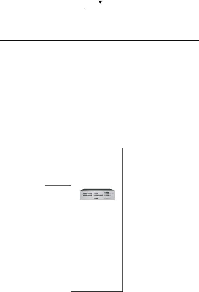
Alcatel OmniPCX Office is available in three models.
Rack 1
-28 ports,
-1 CPU/CPUe slot and 2 reversible slots (no SLI16 board).
-Energy consumption: 1A / 70 W.
-Dimensions: H = 66 mm; W = 442 mm; D = 400 mm.
-Weight: 6 kg.
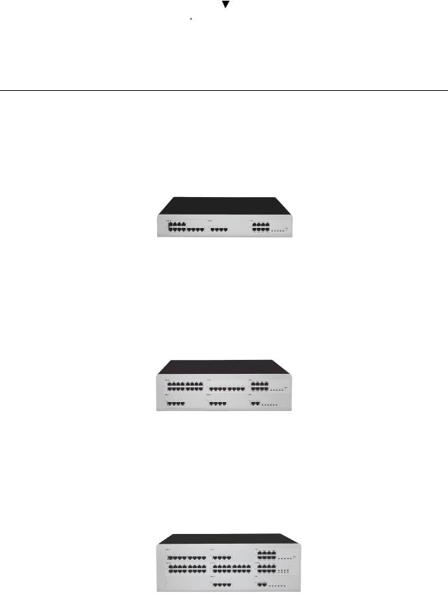
Rack 2
-48 ports.
-1 CPU/CPUe slot and 5 reversible slots.
-Energy consumption: 2 A / 100 W.
-Dimensions: H = 110 mm; W = 442 mm; D = 400 mm.
-Weight: 11 kg.
Rack 3
-96 ports.
-1 CPU/CPUe slot + 4 reversible slots + 4 specific slots (no UAI16 and MIX boards).
-Energy consumption: 2,3 A / 150 W.
-Dimensions: H = 154 mm; W = 442 mm; D = 400 mm.
-Weight: 13 kg.
2/14 |
Réf. 3EH21017BSAA |
Ed. 02 |

File |
4 |
INSTALLATION MANUAL |
PRESENTATION OF THE HARDWARE |
INSTALLATION SYNOPSIS
Z |
Analog station
4970 IO/ EO DECT base
Fax |
Private Network |
|
|
|
(QSIG/ ISVPN) |
ISDN |
@ |
|
|
||
|
|
|
|
|
|
|
Analog Public |
|
|
|
Network |
Z |
Multi Reflexes
Z |
Z |
Reflexes Stations - First
- Easy - Premium - Advanced
Pulse metering
- Elitecost - Printer
General call ringer
Doorphone Loudspeaker
"Please wait" music
Background music
Auxiliaries 


Z |
LAN
PM5
-Integrated voice server
-Integrated CTI server
Integrated Internet applications:
-Internet access
-Proxy s erver
-Cache s erver
-Firewall
-Mail server
10 base T


 Z
Z
 e-Reflexes
TAPI 2.1 or CSTA Server
This equipment must be installed by a qualified installation technician.
Ed. 02 |
Réf. 3EH21017BSAA |
3/14 |

PRESENTATION OF THE HARDWARE INSTALLATION MANUAL
DESCRIPTION OF THE BOARDS
BOARDS |
FUNCTIONS |
OPTIONAL BOARDS |
CONNECTIONS |
|
|
|
|
ATA2 |
2 or 4 analog |
MET: pulse meter receiver |
Analog Trunk Line (TL) and TL- |
ATA4 |
trunk line |
|
SUBS diversion |
|
terminals |
|
|
|
|
|
|
BRA-2 |
2, 4 or 8 T0 basic ac- |
|
ISDN network |
BRA-4 |
cesses |
|
|
BRA-8 |
|
|
|
|
|
|
|
CPU, CPUe |
Processing Unit |
HSL1, HSL2: interconnec- |
Hub, Lan switch or Ethernet |
|
|
tion with extension modules |
terminal |
|
|
XMEM: extended memory |
"Please Wait" message |
|
|
and/or IDE interface for the |
device |
|
|
hard disk |
Background background mu- |
|
|
VoIP: Voice over IP (e-XS |
sic |
|
|
model) |
Alarm |
|
|
AFU: auxiliary functions |
Doorphone |
|
|
|
Loudspeaker. |
|
|
|
General bell |
|
|
|
Pulse metering device |
|
|
|
PC PM5 |
|
|
|
|
CoCPU, |
CoProcessing Unit |
VoIP: Voice over IP |
Hub, LAN switch or Ethernet |
CoCPU@ |
|
SLANX: mini switch |
terminal |
|
|
(CPU/CPUe - |
|
|
|
CoCPU/CoCPU@)link |
|
|
|
|
|
LanX8 |
8 or 16 ports |
|
@ Phones, LAN switch, Hub, |
LanX16 |
10/100 BT Ethernet |
|
etc... |
|
|
|
|
MEX (with |
Controller for extension |
|
|
HSL1 |
modules |
|
|
board) |
|
|
|
|
|
|
|
MIX244 |
0, 2 or 4 T0 basic ac- |
|
ISDN network, Analog Z termi- |
MIX484 |
cesses + 4 or 8 UA inter- |
|
nals and Alcatel Reflexes ter- |
MIX448 |
faces + 4 or 8 Z |
|
minals |
MIX044 |
interfaces |
|
|
MIX084 |
|
|
|
MIX044 |
|
|
|
|
|
|
|
PRA-T1 |
PRA -T2, DASS2, DLT2: |
|
PRA-T2: ISDN network |
PRA-T2 |
30 B-channels + 1 D- |
|
DASS2 UK public/private net- |
DASS2 |
channel; 2048 kbps) |
|
work |
DLT2 |
PRA-T1: 23 B-channels |
|
DLT2: QSIG private network |
|
+ 1 D-channel; 1544 |
|
PRA-T1: Hong-Kong ISDN net- |
|
kbps |
|
work |
|
|
|
|
4/14 |
Réf. 3EH21017BSAA |
Ed. 02 |

File |
4 |
INSTALLATION MANUAL |
PRESENTATION OF THE HARDWARE |
SLI-4 |
4, 8 or 16 |
Z interfaces |
|
Z analog terminals |
SLI-8 |
|
|
|
|
SLI-16 |
|
|
|
|
|
|
|
|
|
UAI-4 |
4, 8 or 16 |
UA interfaces |
|
Alcatel Reflexes terminals |
UAI-8 |
|
|
|
Multi Reflexes |
UAI-16 |
|
|
|
DECT 4070IO/EO base sta- |
|
|
|
|
tions |
|
|
|
|
|
Ed. 02 |
Réf. 3EH21017BSAA |
5/14 |
|
|
|
PRESENTATION OF THE HARDWARE |
INSTALLATION MANUAL |
|
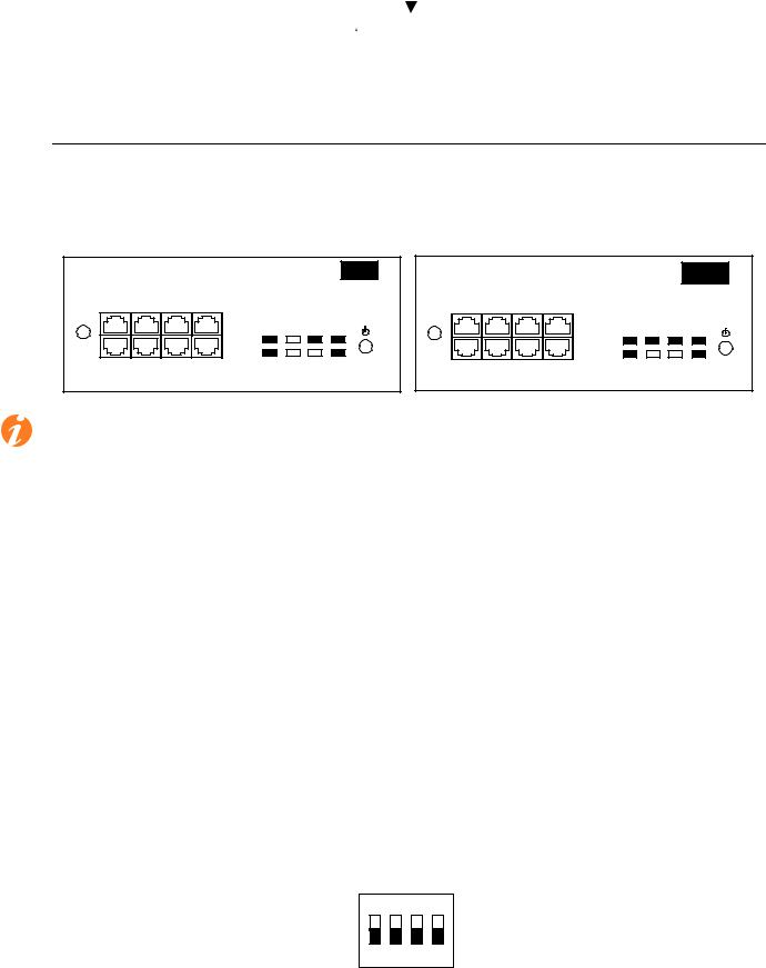
CPU / CPUe Boards
These boards perform the system's central processing unit functions.
PROCESSING UNIT |
|
|
CPU |
PROCESSING UNIT |
|
|
CPUe |
|||
LAN |
AUDIO-OUT |
CONFIG |
|
|
LAN |
WAN |
AUDIO-OUT |
CONFIG |
|
|
|
|
|
LAN |
FAN POWER |
|
|
|
|
LAN WAN |
FAN POWER |
MODULE 1 MODULE 2 |
AUDIO-IN |
DOORPHONE |
MODULE |
CPU |
MODULE 1 |
MODULE 2 |
AUDIO-IN |
DOORPHONE |
MODULE |
CPU |
|
|
|
|
|
|
|
|
|
||
The CPUe board of Alcatel OmniPCX Office's e-XS solution offers all of the following features:
-System central processing unit
-Voice over IP
-Internet Access
Function of the LEDs
Name |
Color |
Function |
|
|
|
CPU |
Green |
CPU correct operation LED (flashing) |
|
|
|
POWER |
Two-colored Red/ |
- Running on mains power: green LED on steady |
|
Green |
- Running on battery: yellow LED on steady |
|
|
- Standby mode: red LED flashing |
|
|
|
FAN |
Two-colored Red/ |
- 2 fans operating correctly: green LED on steady |
|
Green |
- 1 or 2 fans KO: red LED on steady |
|
|
|
LAN |
Green |
LAN correct operation LED (flashes to signal traffic) |
|
|
|
MODULE |
Green |
HSL board installed |
|
|
|
WAN |
Green |
Not in use |
|
|
|
CPU/CPUe board microswitch settings
On
1 2 3 4
6/14 |
Réf. 3EH21017BSAA |
Ed. 02 |
File |
4 |
INSTALLATION MANUAL |
PRESENTATION OF THE HARDWARE |
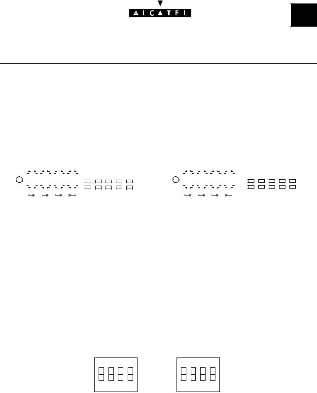
CoCPU / CoCPU@ Boards
These boards perform the following functions:
-CoCPU: Voice over IP and IP Telephony
-CoCPU@: Internet Access, e-mail server, Proxy and VPN.
|
COPROCESSING UNIT |
|
|
|
|
|
|
|
|
|
|
|
|
|
|
COPROCESSING UNIT |
|
|
|
|
|
|
|
|
|
|
|
|||||||||||||||||||||||||||||||||||||||||||||||||||||||||||||||||
|
|
|
|
|
|
|
|
CoCPU |
|
|
|
|
|
|
|
CoCPU@ |
|
|
||||||||||||||||||||||||||||||||||||||||||||||||||||||||||||||||||||||||||
|
|
|
|
LAN |
|
|
|
|
|
|
|
|
|
|
|
|
|
|
|
|
|
|
|
|
|
|
|
|
|
|
|
|
|
|
|
|
|
|
|
|
|
|
LAN |
|
|
|
|
WAN |
|
|
|
|
|
|
|
|
|
|
|
|
|
|
|
|
|
|
|
|
|
|
|
|
|
|
|
|
||||||||||||||||
|
|
|
|
|
|
|
|
|
|
|
|
|
|
|
|
|
|
|
|
|
|
|
|
|
|
|
|
|
|
|
|
|
|
|
|
|
|
|
|
|
|
|
|
|
|
|
|
|
|
|
|
|
|
|
|
|
|
|
|
|
|
|
|
|
|
|
|
|
|
|
|
|
|
|
|
|
|
|
|
|
|
|
||||||||||
|
|
|
|
|
|
|
|
|
|
|
|
|
|
|
|
|
|
|
|
|
|
|
|
|
|
|
|
|
|
LAN |
|
|
|
|
|
|
|
|
|
|
|
|
|
|
|
|
|
|
|
|
|
|
|
|
|
|
|
|
|
|
|
|
|
|
|
|
|
|
|
|
|
|
|
|
|
LAN |
|
WAN |
|
|||||||||||||
|
|
|
|
|
|
|
|
|
|
|
|
|
|
|
|
|
|
|
|
|
|
|
|
|
|
|
|
|
|
|
|
|
|
|
|
|
|
|
|
|
|
|
|
|
|
|
|
|
|
|
|
|
|
|
|
|
|
|
|
|
|
|
|
|
|
|
|
|
|
|
|
|
|
|
|
|
||||||||||||||||
|
|
|
|
|
|
|
|
|
|
|
|
|
|
|
|
|
|
|
|
|
|
|
|
|
|
|
|
|
|
|
|
|
|
|
|
|
|
|
|
|
|
|
|
|
|
|
|
|
|
|
|
|
|
|
|
|
|
|
|
|
|
|
|
|
|
|
|
|
|
|
|
|
|
|
|
|
|
|
|
|
|
|
|
|
|
|
||||||
|
|
|
|
|
|
|
|
|
|
|
|
|
|
|
|
|
|
|
|
|
|
|
|
|
|
|
|
|
|
|
|
|
|
|
|
|
|
|
|
|
|
|
|
|
|
|
|
|
|
|
|
|
|
|
|
|
|
|
|
|
|
|
|
|
|
|
|
|
|
|
|
|
|
|
|
|
|
|
|
|
|
|
|
|
|
|
|
|
|
|
|
|
|
|
|
|
|
|
|
|
|
|
|
|
|
|
|
|
|
|
|
|
|
|
|
|
|
|
|
|
|
|
|
|
|
|
|
|
|
|
|
|
|
|
|
|
|
|
|
|
|
|
|
|
|
|
|
|
|
|
|
|
|
|
|
|
|
|
|
|
|
|
|
|
|
|
|
|
|
|
|
|
|
|
|
|
|
|
|
|
|
|
|
|
|
|
|
|
|
|
|
|
|
|
|
|
|
|
|
|
|
|
|
|
|
|
|
|
|
|
|
|
|
|
|
UNIT1 UNIT 2 |
UNIT 3 |
UP-LINK |
|
CPU |
|
|
|
|
|
|
|
|
|
|
|
|
|
|
|
|
|
|
|
|
|
|
|
|
|
|
|
|
|
|
|
|
UNIT1 |
UNIT 2 UNIT 3 UP-LINK CPU |
|
|||||||||||||||||||||||
|
|
|
UNIT1 UNIT 2 |
|
|
UNIT 3 UP-LINK |
|
|
|
|
|
|
UNIT1 |
|
|
|
|
UNIT 2 |
|
|
|
UNIT 3 UP-LINK |
|
|
|
|
|
|
|
|
|
|
|
|||||||||||||||||||||||||||||||||||||||||||||||||||||||||||
|
|
|
|
|
|
|
|
|
|
|
|
|
|
|
|
|
|
|
|
|
|
|
|
|
|
|
|
|
|
|
|
|
|
|
|
|
|
|
|
|
|
|
|
|
|
|
||||||||||||||||||||||||||||||||||||||||||||||
|
|
|
|
|
|
|
|
|
|
|
|
|
|
|
|
|
|
|
|
|
|
|
|
|
|
|
|
|
|
|
|
|
|
|
|
|
|
|
|
|
|
|
|
|
|
|
|
|
|
|
|
|
|
|
|
|
|
|
|
|
|
|
|
|
|
|
|
|
|
|
|
|
|
|
|
|
|
|
|
|
|
|
|
|
|
|
|
|
|
|
|
|
Function of the LEDs |
|
|
|
|
|
|
|
|
|
|
|
|
|
|
|
|
|
|
|
|
|
|
|
|
|
|
|
|
|
|
|
|
|
|
|
|
|
|
|
|
|
|
|
|
|
|
|
|
|
|
|
|
|
|
|
|
|
|
|
|
|
|
|
|
||||||||||||||||||||||||||||
|
|
|
|
|
|
|
|
|
|
|
|
|
|
|
|
|
|
|
|
|
|
|
|
|
|
|
|
|
|
|
|
|
|
|
|
|
|
|
|
|
|
|
|
|
|
|
|
|
|
|
|
|
|
|
|
|
|
|
|
|
|
|
|
|
|
|
|
|
|
|
|
|
|
|
|
|
|
|
|
|
|
|
|
|
|
|
|
|
|
|
|
|
Name |
|
|
|
|
Color |
|
|
|
|
|
|
|
|
|
|
|
|
|
|
|
|
|
|
Function |
|
|
|
|
|
|
|
|
|
|
|
|
|
|
|
|
|
|
|
|
|
|
|
|
|
|
|
|
|
|
|
|
|
|
|
|
|
|
|
|
|
|
||||||||||||||||||||||||||
|
|
|
|
|
|
|
|
|
|
|
|
|
|
|
|
|
|
|
|
|
|
|
|
|
|
|
|
|
|
|
|
|
|
|
|
|
|
|
|
|
|
|
|
|
|
|
|
|
|
|
|
|
|
|
|
|
|
|
|
|
|
|
|
|
|
|
|
|
|
|
|
|
|
|
|
|
|
|
|
|
|
|
|
|
|
|
|
|
|
|
|
|
CPU |
|
|
|
|
Green |
|
|
|
|
|
|
|
|
|
|
|
|
|
|
|
|
|
|
CPU correct operation LED (flashing) |
|
|
|
|
|
|
|
|
|
|
|
|||||||||||||||||||||||||||||||||||||||||||||||||||||||||
|
|
|
|
|
|
|
|
|
|
|
|
|
|
|
|
|
|
|
|
|
|
|
|
|
|
|
|
|
|
|
|
|
|
|
|
|
|
|
|
|
|
|
|
|
|
|
|
|
|
|
|
|
|
|
|
|
|
|
|
|
|
|
|
|
|
|
|
|
|
|
|
|
|
|
|
|
|
|
|
|
|
|
|
|
|
|
|
|
|
|
||
LAN |
|
|
|
|
Green |
|
|
|
|
|
|
|
|
|
|
|
|
|
|
|
|
|
|
LAN correct operation LED (flashes to signal traffic) |
||||||||||||||||||||||||||||||||||||||||||||||||||||||||||||||||||||
|
|
|
|
|
|
|
|
|
|
|
|
|
|
|
|
|
|
|
|
|
|
|
|
|
|
|
|
|
|
|
|
|
|
|
|
|
|
|
|
|
|
|
|
|
|
|
|
|
|
|
|
|
|
|
|
|
|
|
|
|
|
|
|
|
|
|
|
|
|
|
|
|
|
|
|
|
|
|
|
|
|
|
|
|
|
|
|
|
|
|
||
WAN |
|
|
|
|
Green |
|
|
|
|
|
|
|
|
|
|
|
|
|
|
|
|
|
|
WAN Correct operation LED (flashes to signal traffic); used |
||||||||||||||||||||||||||||||||||||||||||||||||||||||||||||||||||||
|
|
|
|
|
|
|
|
|
|
|
|
|
|
|
|
|
|
|
|
|
|
|
|
|
|
|
|
|
|
|
|
|
|
|
|
|
|
|
|
|
|
|
|
|
|
|
if there is an ADSL modem connection. Available from re- |
|||||||||||||||||||||||||||||||||||||||||||||
|
|
|
|
|
|
|
|
|
|
|
|
|
|
|
|
|
|
|
|
|
|
|
|
|
|
|
|
|
|
|
|
|
|
|
|
|
|
|
|
|
|
|
|
|
|
|
lease R1 onwards. |
|
|
|
|
|
|
|
|
|
|
|
|
|
|
|
|
|
|
|
|
|
|
|
|
|
|
|
|
|
|
|
|
|
|
|
|
|
||||||||
|
|
|
|
|
|
|
|
|
|
|
|
|
|
|
|
|
|
|
|
|
|
|
|
|
|
|
|
|
|
|
|
|
|
|
|
|
|
|
|
|
|
|
|
|
|
|
|
|
|
|
|
|
|
|
|
|
|
|
|
|
|
|
|
|
|
|
|
|
|
|
|
|
|
|
|
|
|
|
|
|
|
|
|
|
|
|
|
|
|
|
||
UNIT 1 - 4 |
|
|
|
|
Green |
|
|
|
|
|
|
|
|
|
|
|
|
|
|
|
|
|
|
LAN interfaces Switches 1 to 4 correct operation LED |
||||||||||||||||||||||||||||||||||||||||||||||||||||||||||||||||||||
UPLINK |
|
|
|
|
|
|
|
|
|
|
|
|
|
|
|
|
|
|
|
|
|
|
|
|
|
|
|
|
|
|
|
|
|
(flashing) |
|
|
|
|
|
|
|
|
|
|
|
|
|
|
|
|
|
|
|
|
|
|
|
|
|
|
|
|
|
|
|
|
|
|
|
|
|
|
|
|
|
|
||||||||||||||||
|
|
|
|
|
|
|
|
|
|
|
|
|
|
|
|
|
|
|
|
|
|
|
|
|
|
|
|
|
|
|
|
|
|
|
|
|
|
|
|
|
|
|
|
|
|
|
|
|
|
|
|
|
|
|
|
|
|
|
|
|
|
|
|
|
|
|
|
|
|
|
|
|
|
|
|
|
|
|
|
|
|
|
|
|
|
|
|
|
|
|
|
|
Microswitch settings |
|
|
|
|
|
|
|
|
|
|
|
|
|
|
|
|
|
|
|
|
|
|
|
|
|
|
|
|
|
|
|
|
|
|
|
|
|
|
|
|
|
|
|
|
|
|
|
|
|
|
|
|
|
|
|
|
|
|
|
|
|
|
|
|
||||||||||||||||||||||||||||
|
|
|
|
|
|
|
|
|
|
|
|
|
|
|
|
|
|
|
|
|
|
|
|
|
|
|
|
|
|
|
|
On |
|
|
|
|
|
|
|
|
|
|
|
|
|
|
|
On |
|
|
|
|
|
|
|
|
|
|
|
|
|
|
|
|
|
|
|
|
|
|
|
|
|
|
|
|
|
|
|
|
|
|
|
|
|
|||||||
|
|
|
|
|
|
|
|
|
|
|
|
|
|
|
|
|
|
|
|
|
|
|
|
|
|
|
|
|
|
|
|
|
|
|
|
|
|
|
|
|
|
|
|
|
|
|
|
|
|
|
|
|
|
|
|
|
|
|
|
|
|
|
|
|
|
|
|
|
|
|
|
|
|
|||||||||||||||||||
|
|
|
|
|
|
|
|
|
|
|
|
|
|
|
|
|
|
|
|
|
|
|
|
|
|
|
|
|
|
|
|
|
|
|
|
|
|
|
|
|
|
|
|
|
|
|
|
|
|
|
|
|
|
|
|
|
|
|
|
|
|
|
|
|
|
|
|
|
|
|
|
|
|
|||||||||||||||||||
|
|
|
|
|
|
|
|
|
|
|
|
|
|
|
|
|
|
|
|
|
|
|
|
|
|
|
|
|
1 |
|
2 |
3 |
4 |
|
|
|
|
1 |
|
2 |
|
3 |
4 |
|
|
|
|
|
|
|
|
|
|
|
|
|
|
|
|
|
|
|
|
|
|
|
||||||||||||||||||||||||||
|
|
|
|
|
|
|
|
|
|
|
|
|
|
|
|
|
|
|
|
|
|
|
|
|
|
|
|
|
|
CoCPU board |
CoCPU@ board |
|
|
|
|
|
|
|
|
|
|
|
||||||||||||||||||||||||||||||||||||||||||||||||||
Ed. 02 |
Réf. 3EH21017BSAA |
7/14 |
|
|
|
PRESENTATION OF THE HARDWARE |
INSTALLATION MANUAL |
|
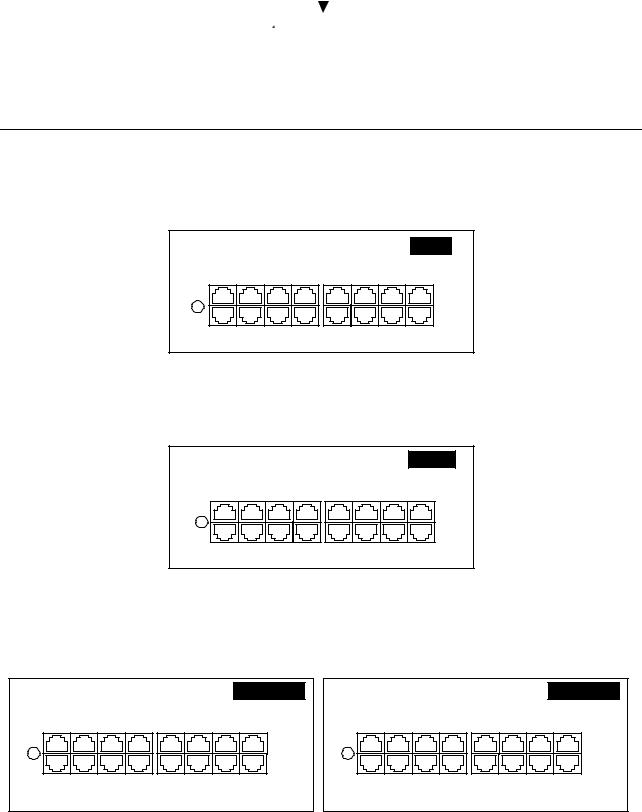
SLI-X boards
These boards allow for the connection of 4, 8 or 16 analog terminals.
ANALOG INTERFACES |
|
|
|
SLI16 |
|||
9 |
10 |
11 |
12 |
13 |
14 |
15 |
16 |
1 |
2 |
3 |
4 |
5 |
6 |
7 |
8 |
UAI-X boards
These boards can connect up 4, 8 or 16 Alcatel Reflexes stations or DECT 4070 IO/EO base stations.
DIGITAL INTERFACES |
|
|
|
UAI16 |
|||
9 |
10 |
11 |
12 |
13 |
14 |
15 |
16 |
1 |
2 |
3 |
4 |
5 |
6 |
7 |
8 |
MIX X/Y/Z boards
These boards can connect up 2 or 4 T0 basic accesses, 4 or 8 analog terminals and 4 or 8 Alcatel Reflexes stations.
MIXED |
|
|
|
|
|
|
MIX 4/ 8/ 4 |
|
|
ISDN T0 |
|
|
ANALOG INTERFACES |
||
1 |
2 |
3 |
4 |
1 |
2 |
3 |
4 |
1 |
2 |
3 |
4 |
5 |
6 |
7 |
8 |
|
|
|
DIGITAL INTERFACES |
|
|
||
MIXED |
|
|
|
|
MIX 4/ 4/ 8 |
||
|
|
ISDN T0 |
|
|
ANALOG INTERFACES |
|
|
1 |
2 |
3 |
4 |
5 |
6 |
7 |
8 |
1 |
2 |
3 |
4 |
1 |
2 |
3 |
4 |
|
DIGITAL INTERFACES |
|
|
ANALOG INTERFACES |
|
||
8/14 |
Réf. 3EH21017BSAA |
Ed. 02 |
 Loading...