


 Loading...
MILLPWRG2
ACU-RITE®
User’s Manual
Controls of the MILLPWRG2
Controls of the MILLPWRG2
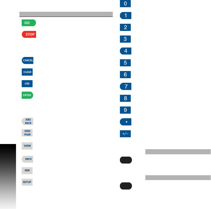
Keys on console
Motion control keys
Key Function
|
GO key (e.g. run a program). |
|
|
|
STOP key (duel function: press once to |
|
pause, press twice to stop a program). |
|
|
Data Entry keys |
|
|
|
Key |
Function |
|
CANCEL key cancels operation, i.e. form. |
|
|
|
CLEAR key clears selections, i.e. values in |
|
a field, a program step. |
|
|
|
USE key completes operation, i.e. data |
|
entered in a form. |
|
|
|
ENTER key completes selection, i.e. |
|
values entered in a field. |
|
|
Function keys |
|
|
|
Key |
Function |
|
ABS/INCR key toggles between Absolute |
|
or Incremental positioning. |
|
|
|
DRO/PGM key toggles between the DRO |
|
display or Program mode display. |
|
|
|
VIEW key opens menu for setting part |
|
graphic display parameters, i.e. type, |
|
orientation. |
|
|
|
INFO key opens on-screen manual. |
|
|
|
MM key toggles between INCH or MM |
|
mode. |
|
|
|
SETUP key opens configuration menu. |
|
|
Numerical keys
Key |
Function |
|
|
|
ZERO key. |
||
|
|
|
|
|
ONE key. |
||
|
|
|
|
|
TWO key. |
||
|
|
|
|
|
THREE key. |
||
|
|
|
|
|
FOUR key. |
||
|
|
|
|
|
FIVE key. |
||
|
|
|
|
|
SIX key. |
||
|
|
|
|
|
SEVEN key. |
||
|
|
|
|
|
EIGHT key. |
||
|
|
|
|
|
NINE key. |
||
|
|
|
|
|
DECIMAL key. |
||
|
|
|
|
|
PLUS / MINUS key. |
||
|
|
|
|
Axis Keys |
|
|
|
|
|
|
|
Key |
|
Function |
|
|
|
AXIS keys open the datum, or preset |
|
|
|
form. |
|
|
|
|
|
Soft Keys |
|
|
|
|
|
|
|
Key |
|
Function |
|
|
|
SOFT KEYS performs the function directly |
|
|
|
above it. |
|
|
|
|
|
ii
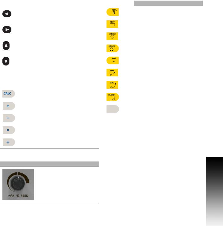
Move Table and Navigation keys
Key |
Function |
|
LEFT ARROW key will move the table or |
|
display cursor depending on the function |
|
selected. |
|
|
|
RIGHT ARROW key will move the table or |
|
display cursor depending on the function |
|
selected. |
|
|
|
UP ARROW key will move the table or |
|
display cursor depending on the function |
|
selected. |
|
|
|
DOWN ARROW key will move the table or |
|
display cursor depending on the function |
|
selected. |
|
|
Calculator Function keys
Key |
Function |
|
CALC key opens the calculator. |
|
|
|
PLUS key. |
|
|
|
MINUS key. |
|
|
|
MULTIPLIER key |
|
|
|
DIVIDE key. |
Potentiometer for feed rate override
Feed rate override
Milling Function keys
Key |
Function |
|
TOOL key opens the SET TOOL |
|
Dialogue. |
|
|
|
RECT key opens the Rectangle milling |
|
popup menu. |
|
|
|
CIRCLE key opens the Circle milling |
|
popup menu. |
|
|
|
HOLES key opens the Hole pattern popup |
|
menu. |
|
|
|
POS key opens the POSITION / DRILL |
|
data input dialogue. |
|
|
|
LINE key opens the MILL LINE data |
|
input dialogue. |
|
|
|
ARC key opens the MILL ARC data input |
|
dialogue. |
|
|
|
BLEND key opens the BLEND \ |
|
CHAMFER data input dialogue. |
|
|
|
BLANK key opens the user defined milling |
|
function data input form. |
|
|
Peripherals Supported:
USB memory devices; e.g. a memory stick.
Networking, USB pointing devices; e.g. a mouse, USB keyboard.
Controls of the MILLPWRG2
ACU-RITE MILLPWRG2 |
iii |

Controls of the MILLPWRG2
iv

Manual Information
Message symbols
Attention!
This symbol indicates that there is one or more of the following risks when using the described function
Danger to work piece
Danger to fixtures
Danger to tool
Danger to machine
Danger to operators
Damage!
This symbol indicates that there is risk of MILLPWRG2 damage, or electrical shock if instructions are not adhered to.
Different from machine to machine!
This symbol indicates that instructions may apply differently from one type of machine to another type of machine.
Refer to another Manual!
This symbol indicates that information required is located elsewhere (i.e. Machines Owner Manual).
Advice!
This symbol indicates that an Advice tip is being provided. Important, and/or additional information about the function described.
Manual Information
ACU-RITE MILLPWRG2 |
v |

Manual Information
Fonts Used in this manual
Reference to the: Console HARD KEYS.
Reference to the: Display Screen Soft Keys.
Reference to the: Display Screen DIALOGUES.
Reference to the: Display Screen FIELDS.
Changes (errors)
HEIDENHAIN CORPORATION is continuously striving to improve. Please help HEIDENHAIN CORPORATION by sending your request to the following e-mail address: sales@heidenhain.com
Visit www.ACU-RITE.com for latest version of this manual.
Model, Software and Features
This manual describes functions and features provided by MILLPWRG2 as of the following NC software number.
Console model |
NC software number |
ACU-RITE MILLPWRG2 Software |
751005-01 |
The machine tool builder may not allow some of the functions described in this manual, therefore they may not be among the features provided by the MILLPWRG2 on your machine tool.
The machine tool builder representative can assist with becoming familiar with the features of the machine.
Many machine manufacturers, as well as HEIDENHAIN Corp., offer programming courses for the MILLPWRG2. We recommend these courses as an effective way of improving your programming skill and sharing information and ideas with other MILLPWRG2 users.
Intended place of operation
The MILLPWRG2 is intended for use primarily in industrially-zoned areas. Refer to the respective installation manual for additional information.
vi

New Functions of Software
751005-01-01
Zero Incremental was added to Section 2.2.
Manual Information
ACU-RITE MILLPWRG2 |
vii |

Manual Information
Changed Functions of Software
751005-01-01
Blend/Chamfer information input in Section 8.1 has been redefined.
Preset Moves information input in Section 2.2 has been redefined.
Display:Peck\Pass in Section 9.1 has a note added that the limit of pecks or passes is 9999.
751005-01-02
The off-line software described in Section 11.1now requires the purchase of a USB Protection Module for operation.
Custom Pocket: The tool path for custom pockets and islands, described in Section 8.2, has changed to use the programmed cutting convention.
751005-01-03
A message box warning that the table limits are not established prior to homing was added to Section 1.1.
751005-01-04
Part Graphics: The show tool path and show step number options were removed from the graphics view in Section 5.1.
Probing examples were added to Section 6.1.
viii

MILLPWRG2 Access Code
Access Code
Attention!
The parameter access code is 8891
Access to Machine Parameter Operations
The access code must be entered before the installation setup parameters can be accessed or changed.
Press the SETUP key to enter the Job Setup dialogue.
Press the Config Data soft key, and enter the access code in the yellow message bar.
Attention!
To prevent setup parameters from being changed, remove this page from the manual after initial system setup. Retain this information in a safe place for future use.
MILLPWRG2 Access Code
ACU-RITE MILLPWRG2 |
ix |

MILLPWRG2 Access Code
x
Table of Contents |
|
Controls of the MILLPWRG2 |
|
Keys on console........................................................................................................ |
ii |
Motion control keys ............................................................................................. |
ii |
Data Entry keys.................................................................................................... |
ii |
Function keys....................................................................................................... |
ii |
Numerical keys .................................................................................................... |
ii |
Axis Keys ............................................................................................................. |
ii |
Soft Keys.............................................................................................................. |
ii |
Move Table and Navigation keys ............................................................................. |
iii |
Calculator Function keys.......................................................................................... |
iii |
Potentiometer for feed rate override ....................................................................... |
iii |
Milling Function keys ............................................................................................... |
iii |
Peripherals Supported: ............................................................................................ |
iii |
Manual Information |
|
Message symbols..................................................................................................... |
v |
Fonts Used in this manual .................................................................................. |
vi |
Model, Software and Features ................................................................................ |
vi |
Intended place of operation ................................................................................ |
vi |
MILLPWRG2 Access Code |
|
Access Code............................................................................................................ |
ix |
Access to Machine Parameter Operations .............................................................. |
ix |
1.1 MILLPWRG2 |
|
ACU-RITE conversational, and G-code format ......................................................... |
2 |
Powering Up ............................................................................................................ |
3 |
E-STOP and Shutdown ............................................................................................ |
4 |
Find Home ............................................................................................................... |
6 |
Disengage Z Axis feature......................................................................................... |
7 |
Disengaging the Z axis drive: .............................................................................. |
7 |
Re-engaging the Z axis drive............................................................................... |
7 |
Writing Programs..................................................................................................... |
8 |
Overview............................................................................................................. |
8 |
1.2 Operating in 2 Axes and 3 Axes Modes |
|
Overview ................................................................................................................. |
9 |
Program Steps in 2 Axis Mode ................................................................................ |
9 |
Selecting 2 Axis Mode on 3 Axis Systems ............................................................ |
10 |
ACU-RITE MILLPWRG2 |
xi |
1.3 Console |
|
Operating Console ................................................................................................. |
11 |
Rear Panel.............................................................................................................. |
11 |
Screen Navigation.................................................................................................. |
12 |
DRO Mode display............................................................................................ |
12 |
PGM Mode display ........................................................................................... |
12 |
Dialogues, and Drop Down Menus........................................................................ |
13 |
Operator Prompts ............................................................................................. |
13 |
Cursor ............................................................................................................... |
13 |
General Operating Guidelines................................................................................ |
14 |
Operating Modes.............................................................................................. |
15 |
Popup Menus ................................................................................................... |
16 |
Keyboard........................................................................................................... |
17 |
Special Characters ............................................................................................ |
17 |
Navigational Soft keys ...................................................................................... |
17 |
Editing Keys ...................................................................................................... |
18 |
Calculator ............................................................................................................... |
18 |
Numeric Keypad ............................................................................................... |
18 |
Context Sensitive Help .......................................................................................... |
19 |
Using Context Sensitive Help ........................................................................... |
19 |
Console Keypad ..................................................................................................... |
20 |
1.4 Operating Mode Screens |
|
Display navigation .................................................................................................. |
21 |
DRO display screen ............................................................................................... |
21 |
Program Display Screen ........................................................................................ |
22 |
1.5 Accessories |
|
Electronic Edge Finder........................................................................................... |
22 |
2.1 Conventions |
|
Axis Conventions ................................................................................................... |
24 |
Count Direction................................................................................................. |
24 |
X axis ................................................................................................................ |
24 |
Y axis ................................................................................................................ |
24 |
Z axis................................................................................................................. |
24 |
Cartesian Coordinates............................................................................................ |
24 |
Polar Coordinates................................................................................................... |
24 |
Absolute and incremental work piece positions .................................................... |
25 |
Absolute work piece positions.......................................................................... |
25 |
Incremental work piece positions..................................................................... |
25 |
Setting the datum .................................................................................................. |
26 |
Overview .......................................................................................................... |
26 |
xii
2.2 Manual Machine Positioning |
|
Move Table ............................................................................................................ |
27 |
Changing the Mode .......................................................................................... |
27 |
Incremental Moves ........................................................................................... |
27 |
Continuous Moves............................................................................................ |
27 |
Adjusting the Feedrate...................................................................................... |
28 |
Preset Moves.................................................................................................... |
28 |
Zero Incremental............................................................................................... |
28 |
3.1 DRO Manual Data Input |
|
Overview ............................................................................................................... |
30 |
DRO Screen........................................................................................................... |
31 |
Status Bar Display.................................................................................................. |
32 |
Move Table ............................................................................................................ |
33 |
Milling Function ..................................................................................................... |
33 |
Zeroing an Axis ...................................................................................................... |
34 |
Teach Position ....................................................................................................... |
34 |
Electronic Edge Finder........................................................................................... |
35 |
Skewing ................................................................................................................. |
36 |
Milling Function Keys............................................................................................. |
37 |
DRO Operations .................................................................................................... |
38 |
Rectangle milling............................................................................................... |
38 |
Rectangle milling example ................................................................................ |
38 |
Circle milling...................................................................................................... |
39 |
Circle milling example ....................................................................................... |
39 |
DRO Mill Cycles..................................................................................................... |
40 |
3.2 Calculator |
|
Accessing the calculator ........................................................................................ |
41 |
Using the calculator to insert data .................................................................... |
42 |
Trig Functions ................................................................................................... |
42 |
4.1 Tool Table |
|
Overview ............................................................................................................... |
44 |
Tool Compensation Required Data ........................................................................ |
44 |
Tool numbers / Tool names ................................................................................... |
45 |
Locating the Tool Table.......................................................................................... |
45 |
Tool Table .............................................................................................................. |
46 |
Editing the tool table ......................................................................................... |
46 |
Editing an existing tool...................................................................................... |
47 |
Tool Table Structure .............................................................................................. |
47 |
Tool table: Standard tool data ........................................................................... |
47 |
ACU-RITE MILLPWRG2 |
xiii |
4.2 Tool Data |
|
Tool-Length Offsets............................................................................................... |
48 |
Teaching Tool Length Offsets in the Tool Table ............................................... |
48 |
Diameter Offset in Tool Table................................................................................ |
49 |
Tool Radius Offset ................................................................................................. |
50 |
Moving without radius offset............................................................................ |
50 |
Machining with radius offset ............................................................................ |
51 |
Radius offset: Machining corners ..................................................................... |
52 |
5.1 Programming Introduction |
|
Program Display mode .......................................................................................... |
54 |
Display area ...................................................................................................... |
54 |
Program Function Screen ...................................................................................... |
55 |
Folder View....................................................................................................... |
55 |
Program Drawing View.......................................................................................... |
56 |
Program Screen Display ........................................................................................ |
57 |
Program Mode Soft Keys ...................................................................................... |
58 |
Program Functions................................................................................................. |
59 |
Program Functions soft keys ............................................................................ |
59 |
View hard key ........................................................................................................ |
62 |
Step Functions soft keys ....................................................................................... |
63 |
Program Steps soft keys ....................................................................................... |
64 |
Clear Program soft key .......................................................................................... |
65 |
Save/Discard soft key ............................................................................................ |
65 |
Run Options soft keys ........................................................................................... |
66 |
Program Saving...................................................................................................... |
67 |
Saving a Program.............................................................................................. |
67 |
5.2 Program Mode Functions |
|
Program Type Filter ............................................................................................... |
68 |
USB Access ........................................................................................................... |
68 |
5.3 Creating programs overview |
|
New Part Program ................................................................................................. |
69 |
xiv
6.1 Conversational Programming |
|
Programming Considerations ................................................................................ |
72 |
“From” and “To” points ................................................................................... |
72 |
Depth of Cut ..................................................................................................... |
72 |
Pass .................................................................................................................. |
72 |
Tool Offset........................................................................................................ |
73 |
Datum Selection ............................................................................................... |
73 |
Absolute vs. Incremental Dimensions .............................................................. |
74 |
Continuous Milling ............................................................................................ |
74 |
Fundamentals for Creating a Program ................................................................... |
75 |
Entering milling steps ....................................................................................... |
75 |
Adding/Inserting milling steps........................................................................... |
76 |
Editing or Deleting a milling step ...................................................................... |
76 |
Program Errors.................................................................................................. |
77 |
Program Edited ................................................................................................. |
77 |
Running a Program ................................................................................................ |
78 |
Skewing a Part .................................................................................................. |
78 |
Establishing a Datum ............................................................................................. |
80 |
Overview........................................................................................................... |
80 |
Steps to Establish the datum............................................................................ |
81 |
X Axis Datum: ................................................................................................... |
82 |
Y Axis Datum .................................................................................................... |
82 |
Z Axis Datum .................................................................................................... |
82 |
Retract Z ........................................................................................................... |
83 |
Using an electronic edge finder ........................................................................ |
83 |
Setting the datum on an edge .......................................................................... |
84 |
Setting the datum at the centerline .................................................................. |
85 |
Setting the datum at the center of a circle ....................................................... |
85 |
Test the Datum Setting..................................................................................... |
86 |
Testing a MILLPWRG2 Program ....................................................................... |
87 |
Single Step........................................................................................................ |
88 |
Dry Run............................................................................................................. |
88 |
Graphics Only.................................................................................................... |
88 |
Machining Your Part .............................................................................................. |
89 |
Potentiometer for Feedrate Override .................................................................... |
90 |
Manually Positioning the Quill .............................................................................. |
91 |
6.2 Folders |
|
Folder Functions .................................................................................................... |
92 |
Folders .............................................................................................................. |
92 |
Creating a Folder............................................................................................... |
92 |
Naming a new folder......................................................................................... |
93 |
Deleting a Folder............................................................................................... |
93 |
Saving a Program .............................................................................................. |
93 |
Naming a Program ............................................................................................ |
94 |
Deleting a Program ........................................................................................... |
94 |
ACU-RITE MILLPWRG2 |
xv |
Loading a MILLPWRG2 (MPT) Program ............................................................ |
95 |
Importing a DXF drawing .................................................................................. |
96 |
G-code Programs ................................................................................................... |
97 |
Loading a G-code Program ............................................................................... |
97 |
Running a G-Code Program .............................................................................. |
98 |
Starting or Stopping a G-code Program ........................................................... |
98 |
G-code and M-Code Definitions............................................................................. |
99 |
G-code .............................................................................................................. |
99 |
M-Code Definition........................................................................................... |
103 |
Additional G-code Conventions for MILLPWRG2 ............................................ |
106 |
Backing Up a Program ......................................................................................... |
107 |
Copy and Paste programs............................................................................... |
107 |
Program Errors................................................................................................ |
108 |
7.1 Demonstration Program |
|
Overview ............................................................................................................. |
110 |
Selecting Datum ............................................................................................. |
110 |
Begin Programming ............................................................................................. |
111 |
Selecting A Tool.............................................................................................. |
111 |
Programming a line......................................................................................... |
112 |
Programming an Arc ....................................................................................... |
113 |
Programming the connecting Line.................................................................. |
114 |
Programming the lower vertical Line.............................................................. |
115 |
Programming the lower angle Line................................................................. |
116 |
Programming the upper angle Line ................................................................ |
117 |
Programming a Blend ..................................................................................... |
118 |
Closing the contour......................................................................................... |
119 |
Tool Change for the Bolt hole Pattern ............................................................ |
120 |
Programming the Bolt circle ........................................................................... |
121 |
Tool Change for the Rectangular Pocket ........................................................ |
122 |
Programming the Rectangular Pocket ............................................................ |
123 |
Testing the Program ............................................................................................ |
124 |
Graphics only .................................................................................................. |
124 |
Dry Run with table movement........................................................................ |
124 |
Running the Program........................................................................................... |
125 |
Tool Changes ....................................................................................................... |
126 |
Clearing the Program ........................................................................................... |
126 |
xvi
8.1 Milling and Drilling |
|
Overview ............................................................................................................. |
128 |
Selecting A Tool .............................................................................................. |
129 |
Repeatable Tool Length Offsets.......................................................................... |
131 |
Programming a Tool........................................................................................ |
131 |
Changing to a Tool of unknown length in DRO mode .................................... |
131 |
Changing to a Tool of unknown length in a program ...................................... |
133 |
Position / Drill....................................................................................................... |
134 |
Line ...................................................................................................................... |
135 |
Arc ....................................................................................................................... |
136 |
Blend/Chamfer..................................................................................................... |
137 |
Rectangular Milling Functions.............................................................................. |
140 |
Rectangle Pocket ............................................................................................ |
140 |
Tool Path Description:..................................................................................... |
141 |
Rectangle Frame............................................................................................. |
142 |
Rectangle Face ............................................................................................... |
144 |
Rectangle Slot................................................................................................. |
146 |
Circular Milling Functions..................................................................................... |
148 |
Circle Pocket................................................................................................... |
148 |
Circle Frame.................................................................................................... |
150 |
Circle Ring....................................................................................................... |
152 |
Circle Helix ...................................................................................................... |
154 |
Hole Patterns ....................................................................................................... |
155 |
Row of Holes .................................................................................................. |
155 |
Hole Frame and Array ..................................................................................... |
157 |
Bolt Circle Patterns ......................................................................................... |
159 |
8.2 Additional Milling Functions |
|
Step Functions soft key ....................................................................................... |
160 |
Explode ........................................................................................................... |
160 |
Reverse Step .................................................................................................. |
161 |
Reverse Path................................................................................................... |
161 |
Change Steps.................................................................................................. |
162 |
Shift Steps ...................................................................................................... |
162 |
Delete Steps ................................................................................................... |
163 |
Copy/Move Steps ........................................................................................... |
163 |
Custom Pockets .................................................................................................. |
164 |
Custom Pocket ............................................................................................... |
164 |
Island............................................................................................................... |
165 |
Tool Path Description for Custom Pocket, and Islands................................... |
165 |
Contour ........................................................................................................... |
166 |
Repeat, Rotate, ................................................................................................... 168 |
|
Repeat............................................................................................................. |
168 |
Rotate ............................................................................................................. |
168 |
Mirror .............................................................................................................. |
169 |
ACU-RITE MILLPWRG2 |
xvii |
Other Steps ......................................................................................................... |
169 |
Engrave Line ................................................................................................... |
170 |
Engrave Arc .................................................................................................... |
171 |
Comment Step ............................................................................................... |
172 |
Dwell............................................................................................................... |
173 |
Reference Point .............................................................................................. |
173 |
9.1 Setup |
|
Overview ............................................................................................................. |
176 |
Setup .............................................................................................................. |
176 |
Tool Table ....................................................................................................... |
176 |
Error Log ......................................................................................................... |
176 |
Job Setup............................................................................................................. |
177 |
Job Setup........................................................................................................ |
177 |
Scale Factor .................................................................................................... |
178 |
Feed Rate ...................................................................................................... |
178 |
Display: Peck\Pass.......................................................................................... |
178 |
Job Clock - Parts Counter ............................................................................... |
179 |
Probing............................................................................................................ |
179 |
Display Grid..................................................................................................... |
180 |
Travel Limits ................................................................................................... |
180 |
Tool Table ............................................................................................................ |
183 |
Error Log .............................................................................................................. |
183 |
Service Files.................................................................................................... |
184 |
10.1 Updating System Software |
|
Software Update.................................................................................................. |
186 |
Procedure for updating the software................................................................... |
186 |
11.1 MILLPWR Off-Line Software |
|
Off-Line Simulator................................................................................................ |
188 |
System Requirements ......................................................................................... |
188 |
Installation............................................................................................................ |
189 |
Operation ............................................................................................................. |
189 |
On Screen Keypad ............................................................................................... |
190 |
Keyboard Shortcuts ............................................................................................. |
190 |
Updating .............................................................................................................. |
192 |
xviii

Introduction
1.1 MILLPWRG2
1.1 MILLPWRG2
The ACU-RITE MILLPWRG2 control is a workshop-oriented contouring control that enables you to program conventional machining operations right at the machine in an easy-to-use conversational programming language. It is designed for milling and drilling machine tools, with up to 3 axes.
MILLPWRG2 was developed to satisfy the wants and needs of tool and die makers and other machinists where manual and automated operation are both useful and needed. MILLPWRG2 will enable you to maximize your throughput by significantly reducing set-up time, scrap, and other non-productive operations, thereby increasing your efficiency, productivity and profitability.
The MILLPWRG2 has many powerful features that will improve your productivity. The screen layout is clearly arranged in such a way that the functions are easy to access, fast and user friendly.
MILLPWRG2 is a closed-looped system with positioning feedback provided by ACU-RITE precision glass scales (1µm/0.00005" resolution). MILLPWRG2 also includes Position-Trac™, an advanced, unique feature that enables you to easily, quickly and accurately re-establish work piece zero after shutting down, or power loss.
ACU-RITE conversational, and G-code format
The ACU-RITE conversational programming format is a method of writing programs; g-code (ISO) programming can be used, and run, but can not be edited. Preview graphics in the editor illustrate the individual machining steps for programming the contour as well as the corresponding tool path generated. A production drawing does not need to be dimensioned for NC programming, the MILLPWRG2 can be programmed using the dimensions directly from the production drawing. The programming format is the same as used in previous MILLPWR products. Always verify old programs before machining with MILLPWRG2.
2 |
1 Introduction |

Powering Up
The MILLPWRG2 console does not disconnect the power supply to the spindle motor. It can only be disconnected by turning off the main power supply.
Turn the power switch On [1], (to the I position) on the MILLPWRG2 console which is located on the back of the unit.
Follow the builder’s instructions to turn off the machine.
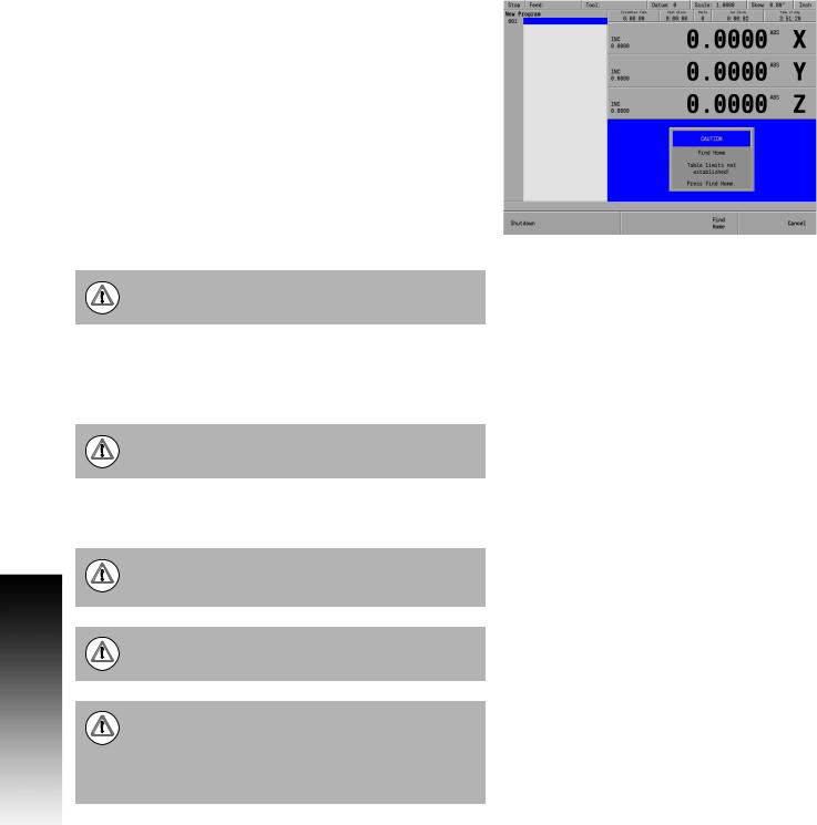
The start up screen with 3 soft keys will be displayed; Shut Down, Find Home, and Cancel. After pressing either the Find Home, or Cancel soft key, the default DRO screen will be displayed.
It is strongly recommended that the MILLPWRG2 performs the Find Home feature at start up, prior to any other action taken.
If a program was loaded when the MILLPWRG2 was shut down, that same program will be reloaded when the unit is powered up again.
If the MILLPWRG2 did not perform the Find Home feature at start up, press the Datum soft key from the default DRO screen to display the Home soft key. Press the Home soft key then the Find Home soft key will be displayed.
1.1 MILLPWRG2
ACU-RITE MILLPWRG2 |
3 |
1.1 MILLPWRG2
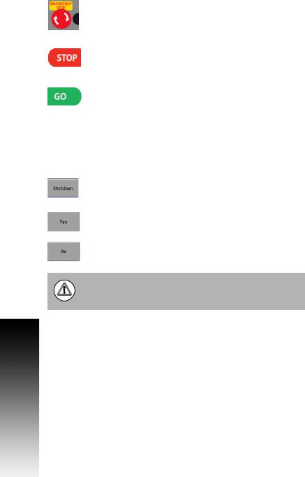
E-STOP and Shutdown
The E-STOP is used for emergency program shut down by turning off the servo motors. It does not shut down the spindle motor. The spindle motor must always be manually stopped using the spindle switch to stop the motor, and the cutting tool.
When the E-STOP button is pressed, the servo motors are stopped, and the quill can be raised.
When the STOP key is pressed once, the servo motors pause, but are still active. All axes are locked, and can not be moved.
The program can now either continue by pressing the GO key, or stopped by pressing the STOP key a second time.
If the STOP key is pressed a second time canceling the program, the spindle motor must be stopped, and the tool raised before moving any of the remaining axes.
Shutting down the MILLPWRG2 system is done by using the Shutdown soft key.
Press the Shutdown soft key to shut down the MILLPWRG2 system. This soft key is available in both DRO and PGM mode.
Confirm the shut down by pressing the Yes soft key.
Press the No soft key to cancel and exit the shut down procedure.
Always shutdown the MILLPWRG2 before turning power off to the machine. Refer to the builder's instructions for for additional information on turning power off.
4 |
1 Introduction |

Emergency Stop (E-STOP)
Press E-STOP to take all axes servos offline. This ends all machine movement, and allows the quill to be raised to move the tool out of the way.
To reset the E-STOP, turn the rotary switch clockwise in the direction of the arrows. The switch pops outward, and is reset.
Resetting E-STOP does not reactivate the servos.
Activating/Resetting the Servos
For safety reasons, the mill powers up with the servomotors disengaged. While the servos are disengaged the mill axes cannot move under servo power. The axes can be manually positioned if necessary.
Reset the servos as follows:
If a limit switch disengaged the servos, manually reposition the machine inside its normal range of travel.
If a miscount occurs, press the Find Home soft key to reset the servos and return all axes to their home position.
1.1 MILLPWRG2
ACU-RITE MILLPWRG2 |
5 |
1.1 MILLPWRG2
Find Home
You should find home before a program is run, or immediately after startup.
During start up, the Find Home soft key is provided on the start up screen soft key area.
If the find home step is not performed at initial start up, it can be initiated at any time during operation. Press the Datum soft key, then press the Home soft key, and then press the Find Home soft key.
A 3 axes system will move the table and quill. They will automatically move a few inches along the Z, Y, and then X to find home. If a W axis exists (i.e. coupling knee to quill) then the control will prompt you to move the W manually to home it.
A 2 axes system will move the table. The table will automatically move a few inches along the Y, and then X to find home. Then the control will prompt you to move the Z quill manually to home it. If a W axis exists (i.e. coupling knee to quill) then the control will prompt you to move the W manually also to home it.
Before finding home with a 2 axes system, the quill must be fully raised first.
When finding home, the MILLPWRG2 will use (on machines equipped with ACU-RITE glass scales), the Position-Trac™ distance-encrypted reference mark line pattern. This line pattern allows MILLPWRG2 to accurately find home and re-establish workpiece zero from any position.
Finding home applies to the X, Y, Z, and W axes.
Position-Trac will accurately re-establish workpiece zero after power loss, or shut down. After home has been found, the tool’s position (relative to the most recent datum set) will be displayed.
Not finding home before moving the table will risk exceeding the table's travel limits, and possible damage to the machine, and the MILLPWRG2 system.
Programs will not be allowed to run if the homing process does not complete successfully.
The Find Home soft key is not available if there is an error, and the front panel LED indicator is flashing.
The error must be corrected, and then cleared from the error log. Then homing is allowed.
Refer to Chapter 9 "Error Log" on page 183 for information on opening the error log and deleting errors.
6 |
1 Introduction |
Disengage Z Axis feature
MILLPWRG2 provides the flexibility to switch between 2 axes and 3 axes operation.
Disengaging the Z axis drive:
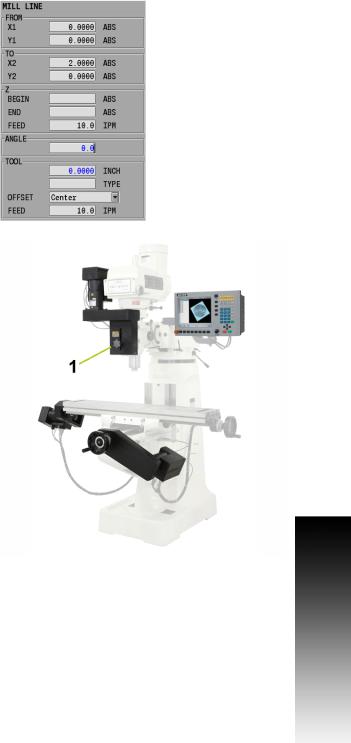
Leave the Z BEGIN field blank when programming a step, or a one time milling operation.
Raise the quill, then loosen the quick release knob [1] on the front of the the Z axis drive system.
When a program step, or milling operation is then performed, the operator is prompted to manually position the quill.
Re-engaging the Z axis drive
Raise the quill handle to seat the ball screw into the nut block (e.g. this would be similar to hitting a dead stop).
Tighten the quick release knob [1].
1.1 MILLPWRG2
ACU-RITE MILLPWRG2 |
7 |
1.1 MILLPWRG2
Writing Programs
Overview
The MILLPWRG2 allows many features to be used without having to write a program. For operations that repeat, or complex machining it is best to write a program. Before writing a program, determine the work-holding device and the location of Part Zero (the point to which all movement is referenced). Since absolute positions are defined from Part Zero, try to select a location that directly corresponds to dimensions provided on the part print, such as the lower left corner of the work. Then you can develop a program. The following is a general approach to programming:
First, select the unit of measurement (Inch/MM) using the MM key. This will place the DRO in the required unit of measure, and all
dialogues will use the selection. If the selection is changed after data has been entered, the MILLPWRG2 will convert the data to the new unit of measure.
The first step in a program selects the tool that is to be used. It’s size can be entered in either Inch or MM regardless of the unit of measure selected in the DRO. The Tool dialogue provides fields for data input for the tool position. This is a tool change position, a location away from the work area where the axes can return for safe tool changing. TOOL POSITION will use the unit of measure that has been selected for the DRO.
The remaining steps in the program describe the required moves, single cycles, and Tool changes to complete the machining.
The next to the last step in the program returns the axes to the Tool change position and ends the program.
After writing a program, verify it. Run it to troubleshoot for errors. Verify that all programmed moves are safe, and accurate to the part print dimensions.
Setup the work piece into the intended holding device.
First run the program in Single-Step Mode to verify that both the program and the setting of Tool Offsets are correct. Single-Step Mode allows you to run the program step-by-step. Make any necessary corrections. Once verified, the program can be run in Auto Mode.
When the finished program is ready for production, back it up on a USB memory device.
If there is an interruption to the power supply, the program is not lost. The program is periodically saved. Verify that the most recent steps (prior to the power failure) are in the program. The fixture zero location is also remembered.
8 |
1 Introduction |

1.2 Operating in 2 Axes and 3 Axes
Modes
Overview
The MILLPWRG2 is capable of running a 2 axes machine (manual Z) or a 3 axes machine with the Z being switched to manual as needed. This User's Manual covers 2 axes and 3 axes operation. This section provides some general guidelines. In 2 axes mode, all Z moves must be made manually.
When running a program, the system will pause and provide a prompt whenever a Z move is required.
The incremental DRO display will show the distance to the Z axis target position.
Press the ABS/INCR key to toggle between absolute and incremental display modes.
In incremental mode, a bar graph is displayed below each axis position. A small blue indicator moves toward the center of the bar as the incremental position approaches 0. When at 0, the blue indicator will be centered.
After moving the Z axis to the programmed position, press the GO key to continue running the program.
Program Steps in 2 Axis Mode
When running a program step in 2 axis mode, not all information in the program step is used. Values may be programmed for Z Pass, Z Peck, and Tool Retract, but they will not be used when running in 2 axis mode.
When prompted to set Z, the incremental display will show the distance to the Z end depth.
After drilling to depth, raise the quill and press the GO key to continue running the program.
For pocket steps, raise the quill and press GO when prompted.
If an additional pass is needed for a step, press STOP to end the program and run the step again.
It may also be necessary to repeat a set of steps for each pass in a program.
1.2 Operating in 2 Axes and 3 Axes Modes
ACU-RITE MILLPWRG2 |
9 |

1.2 Operating in 2 Axes and 3 Axes Modes
Selecting 2 Axis Mode on 3 Axis Systems
To run a program in 2 axis mode, disengage the quill assembly before pressing the GO key.
A prompt will appear indicating that the quill is disengaged.
If this is intentional, press GO and the program will run in 2 axis mode.
To program a specific step to run in 2 axis mode:
Select POSITION for the Z operation type (drill steps).
For pockets, clear the Z begin depth field.
When the step is run, the Z axis servo motor will be turned off to allow manual movement.
Follow all manual Z motion prompts. See "Tool Table" on page 44 for a complete description about using the Tool Table.
10 |
1 Introduction |
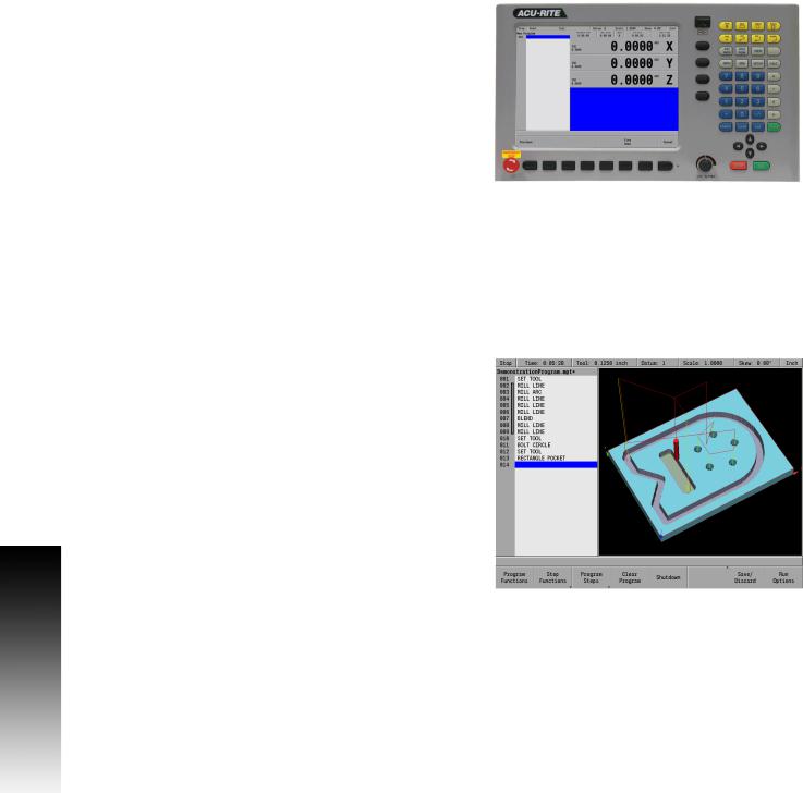
1.3 Console
Operating Console
The ACU-RITE MILLPWRG2 Console has a 12.1-inch Flat-Panel Color Screen Display. The following list of items are located on the front panel.
See "DRO display screen" on page 21 for mapping information of the start up screen.
See "Console Keypad" on page 20 for a full description of the console keypad layout. The individual keys are fully described on page ii of the inside front cover.
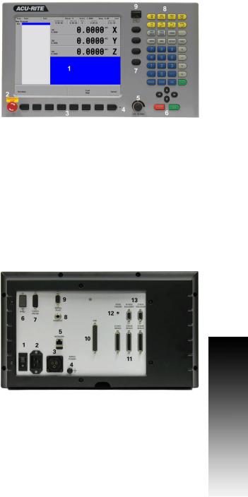
The following features are located on the front panel of the console:
1Color flat panel screen display.
2Emergency “E” Stop
3Soft keys
4Power On indicator light / Error indicator light
5Potentiometer for feed rate override
6Go, Pause/Stop, Navigation keys, and Move Table keys
7Axis keys
8Console keypad
9USB Port
See "Calculator" on page 18 for a full description of the calculator keypad.
Rear Panel
The ACU-RITE MILLPWRG2 DRO rear panel has the following list of items located on the panel.
1Power switch
2Power connector
3Servo Power connector
4Earth (ground) terminal
5Ethernet port
6USB port
7KT 130 Edge Finder
8Pendant (Remote switch)
9RS-232-C connector
10Auxiliary Machine Interface (AMI); for future expansion.
11Servo connector (X, Y, and Z)
12Grounding Edger Finder
13Encoder Inputs (W and Z axis)
1.3 Console
ACU-RITE MILLPWRG2 |
11 |
1.3 Console
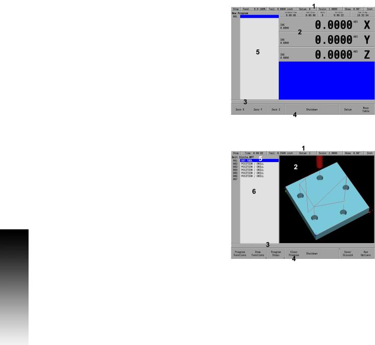
Screen Navigation
The MILLPWRG2 display layout changes between DRO Mode and PGM (Program) Mode by pressing the DRO/PGM key. The following illustrates the differences between the two screen modes.
DRO Mode display
In general, the display changes as different functions are activated. Soft keys in the lower display area change per the function selected. Soft keys perform their associated function by pressing the key directly below it. Basic procedures and features remain the same regardless of which mode is selected. For a complete description of the display areas see "DRO Screen" on page 31.
1Status Bar display for Servo Motor Status, Feed rate, Tool, Datum, Scale, Skew, (Inch/MM), Estimated Time, Part Clock, Parts (run), Job Clock, and Time of Day. See "Status Bar Display" on page 32.
2Axes Display (current position).
3Operator Intervention Message line (OIM).
4Soft keys display area.
5Dialogue box display area for milling functions.
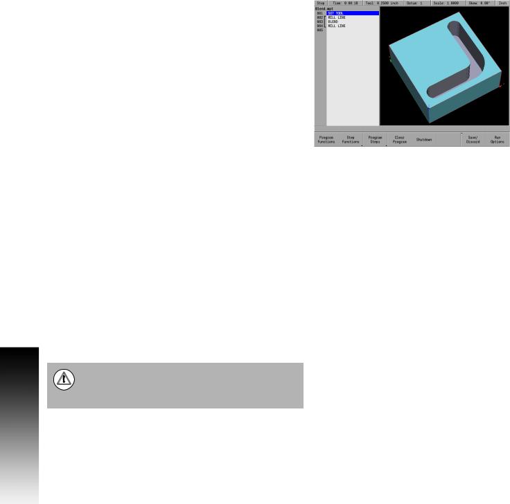
PGM Mode display
When PGM mode is selected, the display changes from DRO mode to display program functions and graphics. Soft keys change to programming functions. All soft keys are run by pressing the corresponding hard key located directly below it. See "Status Bar Display" on page 32 for complete descriptions.
1Status Bar display for Servo Motor Status, Estimated Time, Tool, Datum, Scale, Skew, (Inch/MM).
See "Status Bar Display" on page 32.
2Display window of graph simulation.
3Operator Intervention Message (OIM).
4Soft keys display area.
5Program name.
6Program steps.
12 |
1 Introduction |
Loading...