


DRO 200M™
REFERENCE MANUAL
Readout Parameter Access Code
An access code must be entered before machine-related parameters can be set or changed. This prevents inadvertent adjustments to the setup parameters.
IMPORTANT
The access code is 8891
Refer to the Setup section. Begin by pressing the SETUP key. When “SETUP” is
displayed, press the 8 , 8 , 9 , 1 , and ENTER keys. The readout is now ready for machine parameter setting operations.
IMPORTANT
Supervisors may wish to remove this page from the Reference manual after initially setting up the readout system. Retain in a safe place for future use.
Warranty
ACU-RITE Products and accessories are warranted against defects in material and workmanship for a period of three years from the date of purchase. ACU-RITE will, at its option and expense, repair or replace any part of the ACU-RITE product that fails to meet this warranty. This warranty covers both materials and factory labor. In addition, authorized ACU-RITE service representatives will provide service labor (field service) for a period of one year at no charge. Notice of the claimed defect must be received by ACU-RITE within the warranty period.
This warranty applies only to products and accessories installed and operated in accordance with this reference manual. ACU-RITE shall have no obligation, with respect to any defect or other condition caused in whole or part by the customer’s incorrect use, improper maintenance, modification of the equipment, or by the repair or maintenance of the product by any person except those deemed qualified by ACU-RITE.
Responsibility for loss of operation or diminished performance due to conditions beyond ACU-RITE’s control cannot be accepted by ACU-RITE.
The foregoing warranty obligations are in lieu of all expressed or implied warranties. ACU-RITE INCORPORATED shall not be liable under any circumstances for consequential damages.
30 Day Red Carpet Warranty
All ACU-RITE products are covered by a 30-day Red Carpet Warranty. If in the first 30 days this product fails for any reason, repack it in the original packing materials and contact your Authorized ACU-RITE Distributor for return procedures.

DRO 200M |
Table of Contents |
Introduction ........................................................................................................ |
1 |
A Tour of the Readout.................................................................................................. |
1 |
Front and Back Views............................................................................................... |
1 |
Keypad ..................................................................................................................... |
2 |
Displays.................................................................................................................... |
3 |
Power-On Position Recovery ...................................................................................... |
4 |
Position-Trac ............................................................................................................ |
4 |
Readout Operations.......................................................................................... |
5 |
Clear Key ....................................................................................................................... |
5 |
Absolute and Incremental Displays ............................................................................ |
5 |
Absolute Display....................................................................................................... |
5 |
Incremental Display .................................................................................................. |
5 |
Zeroing the Displays .................................................................................................... |
6 |
Absolute Zero ........................................................................................................... |
6 |
Moving the Absolute Zero......................................................................................... |
8 |
Zeroing at a Center Line ........................................................................................... |
9 |
Incremental Zero....................................................................................................... |
9 |
Presetting.................................................................................................................... |
10 |
Absolute and Incremental Presets.......................................................................... |
11 |
Center-line Presets................................................................................................. |
12 |
Near Zero Warning ..................................................................................................... |
13 |
Centerlines.................................................................................................................. |
13 |
Bolt Hole Patterns ...................................................................................................... |
14 |
Defining the Bolt Hole Pattern................................................................................. |
14 |
Using the Result ..................................................................................................... |
15 |
Tool Offset................................................................................................................... |
16 |
Defining the Offset Direction................................................................................... |
16 |
Using Tool Offsets .................................................................................................. |
17 |
Setup.................................................................................................................. |
18 |
Machine-Related Setup Parameters ......................................................................... |
18 |
Count Direction....................................................................................................... |
18 |
Tool Offset Direction............................................................................................... |
18 |
Encoder Resolution ................................................................................................ |
18 |
Job Setup Parameters................................................................................................ |
19 |
Display Resolution.................................................................................................. |
19 |
Scale Factor ........................................................................................................... |
19 |
Near Zero Warning................................................................................................. |
19 |
Bolt Circle Definition................................................................................................ |
20 |
Linear Error Compensation..................................................................................... |
20 |
Edge Finder Diameter............................................................................................. |
21 |
Installation......................................................................................................... |
22 |
Readout Specifications................................................................................... |
25 |
Troubleshooting .............................................................................................. |
26 |
DRO 200M
!
This symbol alerts you to the fact that important information concerning the installation and operation of this readout has been included in this manual.
Keep these instructions in a secure place for future reference.

DRO 200M |
Introduction |
Introduction
ACU-RITE’s DRO 200 readout series provides application-specific features required for you to obtain the most productivity from your manual machine tools.
The DRO 200M is designed specifically for milling and drilling applications. Special features include an easy to use bolt hole routine, centerline locating, and quick tool offsetting.
A Tour of the Readout |
|
|
|
|
|
|
|
||
Front and Back Views |
|
|
Indicators |
|
|
|
|
|
|
|
|
|
|
|
|
|
|
||
MM |
INCR |
ABS ZERO |
SET |
C/L |
|
ABS |
|
|
|
|
|
|
|
X |
|
MM |
|
SETUP |
|
|
|
|
|
ZERO |
INCR |
|
|||
|
|
|
|
|
|
|
|
||
|
|
|
|
|
|
C |
7 |
8 |
9 |
|
|
|
|
|
|
DIA |
4 |
5 |
6 |
|
|
|
|
|
|
TOOL |
|
|
|
|
|
|
|
Y |
ZERO |
|
1 |
2 |
3 |
|
|
|
|
|
|
BOLT |
|||
|
|
|
|
|
|
CIRCLE |
. |
0. |
|
|
|
|
|
|
|
DEFINE |
+/- |
||
|
|
|
|
|
|
|
|
|
|
|
|
|
|
Z |
ZERO |
USE |
CLEAR |
|
ENTER |
|
|
|
|
|
|
|
|
||
Electrical & fuse rating information
FCC COMPLIANCE
FREQUENCY
VOLTAGE
CURRENT
FUSE
EDGE
FINDER
115V
!
Application-specific
function keys
Electronic
Edge
Finder
Input
|
|
|
|
|
|
|
|
|
|
|
|
INPUT 3 |
INPUT 2 |
INPUT 1 |
|
|
|
|
|
|
|
|
|
|
|
|
|
|
|
|
|
|
|
|
|
|
|
|
|
|
|
|
|
|
|
|
|
|
|
|
|
|
|
|
|
|
|
|
|
3x DRO
PN 2001009 SN 9766554
Encoder inputs
Power switch and |
Ground wire |
Model number and |
voltage selector |
connection |
Serial number |
1
Introduction |
DRO 200M |
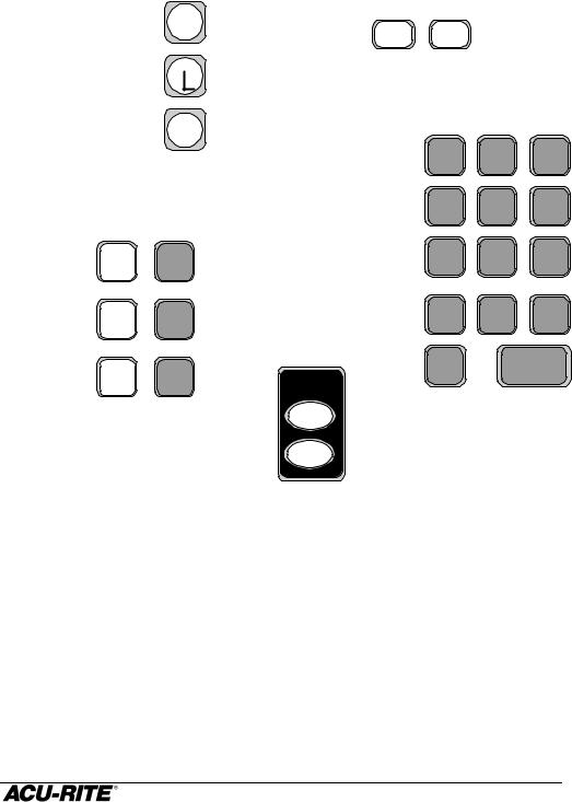
Keypad
Selects absolute or |
ABS |
|
|
|
incremental display |
English / metric |
|
||
INCR |
MM |
|||
|
|
|
conversion |
|
|
|
|
|
|
Used to locate |
C |
|
|
|
centerlines |
|
|
||
|
|
|
||
Compensate for tool |
TOOL |
|
|
|
|
diameter |
|
|
|
|
|
DIA |
|
|
|
|
|
Enter all numeric values |
|
|
|
|
with these |
|
Begin a preset |
X |
ZERO |
Zero an axis display |
|
|
|
|
||
|
Y |
ZERO |
|
|
|
Z |
ZERO |
BOLT |
|
CIRCLE
DEFINE
USE
Use these to define a bolt hole pattern, and use the calculated hole positions.
SETUP |
System setup |
|
parameters |
||
|
7 8 9
4 5 6
1 2 3
. 0 +/-
CLEAR ENTER
2
DRO 200M |
Introduction |
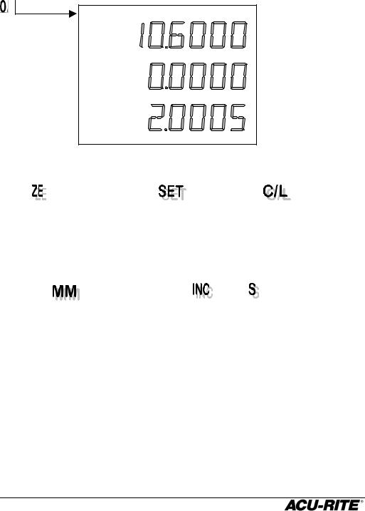
Displays
At the top of the display window is a row of indicators. These tell you the current state of the readout.
MM INCR ABS ZERO SET C/L
Appears when |
Lets you know when |
Tells you when |
setting an |
you are setting a |
the centerline |
absolute zero. |
preset or an absolute |
function is active. |
|
zero. |
|
Appears when you’re
positioning in metric, dark when you’re positioning in inches.
These tell you if the position display is
incremental or absolute. They also refer to the type of preset.
In addition to the lighted indicators along the top of the display, the top axis display will scroll longer messages that will help you step through some of the procedures.
3
Introduction |
DRO 200M |
Power-On Position Recovery
Position-Trac
Certain ACU-RITE encoders, such as the ENC 150, contain closely spaced reference marks that enable the display to show the correct position after a power interruption. The readout will indicate when power has been lost, and will prompt you to move each axis until a reference mark is located. By traversing the reference marks once in each axis, you will re-establish the display position relative to the last known zero. The most you will ever have to move an axis is about one inch. You must move in a positive count direction. A flashing decimal point will indicate that the last position has not been recalled.
If you use an encoder without Position-Trac, the procedure for recovering your position is slightly different. Reference marks on these encoders are about 8” apart. You must find a convenient reference mark and then use the same mark every time.
1.Move near the desired reference mark.
2. Press and hold the INCRABS key until the decimal point starts to flash.
3.Move slowly past the reference mark until the readout recalls its position. You must move in a positive count direction.
4
DRO 200M |
Readout Operations |
Readout Operations
Clear Key
Use the CLEAR key to erase digits that you entered by mistake, or to take you back if you’ve pressed a wrong function key.
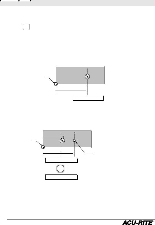
Absolute and Incremental Displays
Absolute Display
Shows the distance from your current position to absolute zero.
|
The drill is positioned at |
|
Absolute Zero, |
1.625 ABS. |
|
also called datum |
|
|
or Workpiece |
1.625 |
|
Zero |
||
|
X 1.625 ABS
Incremental Display
Shows the distance from your current position to incremental zero. An incremental zero is set when you preset a dimension, or when you zero the incremental display.
1.000 -0.625
Absolute
zero.
1.625
X -0.625 INCR
ABS
INCR
The drill is 0.625 on the negative side of the incremental zero.
Incremental zero: the incremental display will read 0.000 when the drill is here.
X1.000 ABS
Automatic Display Switching
Sometimes the readout will switch from one display to the other automatically. When you enter a preset, for example, the display switches to the incremental display so that you can move to zero. Whenever the readout does an automatic display switch, INCR will appear briefly in the display.
5
 Loading...