


 Loading...
200S READOUTS
REFERENCE MANUAL
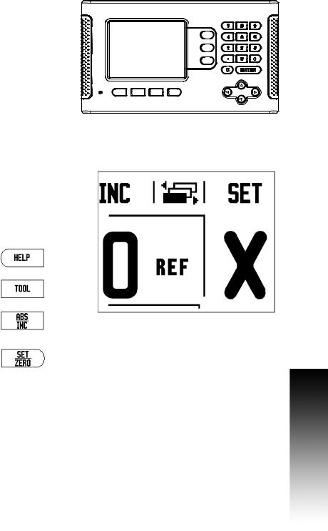
200S Key Layout
1 |
Display Area |
|
|
|
61 |
2 |
Soft keys |
|
|
|
|
3 |
Power Indicator light |
|
|
|
|
4 |
Arrow Keys: Use the UP/DOWN keys to adjust the |
|
1 |
51 |
|
|
screen contrast. |
|
|
||
|
|
|
|
|
|
5 |
Axis Keys |
|
|
|
|
6 |
Numeric Keypad |
|
|
81 |
71 |
7 |
ENTER key |
|
|
||
|
|
|
|
||
8 |
CLEAR key |
3 |
21 |
|
41 |
|
|
|
200S Soft keys
There are multiple pages of soft key functions to select from the operating modes. Use the LEFT/RIGHT arrow keys [4] to cursor through each page. The page indicator in the Status Bar will show the
page orientation. The darkened page indicates the page you are 1 currently on.
1 |
Page Indicator |
|
|
|
|
|
2 |
Set Zero Indicator |
|
|
|
|
|
|
|
21 |
|
|
||
|
|
|
|
|
||
|
|
|
|
|
|
|
|
Soft Key function (Page 1) |
Soft key |
|
|
|
|
|
Opens on-screen help instructions. |
|
|
|
|
|
|
|
|
|
|
|
|
|
Opens the Tool Table. Page 21 for Milling, and |
|
|
|
|
|
|
page 46 for Turning. |
|
|
|
|
|
|
|
|
|
|
|
|
|
Switches display between operating modes |
|
|
|
|
|
|
Actual Value (Absolute) / Distance-to-Go |
|
|
|
|
|
|
(incremental). See page 12. |
|
|
|
|
|
|
|
|
|
|
|
|
|
Toggles between Set/Zero functions. Used |
|
|
|
|
|
|
with individual axis keys (page 19). |
|
|
|
|
|
|
|
|
|
|
|
|
|
|
|
|
|
|
|
|
|
|
|
|
|
|
200S |
i |
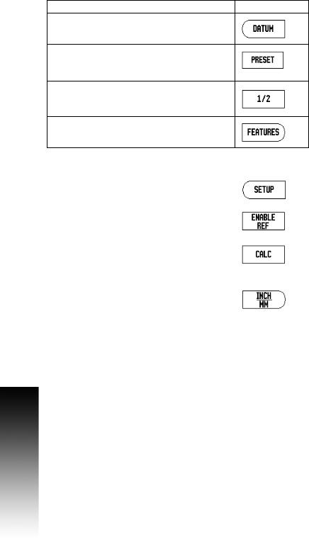
Soft Key function (Page 2) |
Soft key |
Opens the Datum form to set the datum for each axis (page 27).
Opens the Preset form. This form is used to set a nominal position. This is a Distance-To-Go (Incremental) function (page 32).
Used to divide the current position by two (page 35).
Press to select the Circle Pattern, Linear Pattern,
Incline Mill, or Arc Mill table (page 37).
Soft Key function (Page 3) |
Soft key |
Opens the Job Setup menu and provides access to |
|
the Installation Setup soft key (page 13). |
|
|
|
Press when ready to identify a reference mark (page |
|
11). |
|
|
|
Opens the Calculator functions for standard math, |
|
trigonometry, RPM, and Taper for Turning functions. |
|
The CALC key is also available on input forms |
|
where calculations may be required while |
|
inputting data. |
|
|
|
Toggles between inch and millimeter units (page |
|
13). |
|
|
|
ii
Readout Parameter Access Code
An access code must be entered before machine-related installation parameters can be set or changed. This prevents inadvertent adjustments to the installation setup parameters.
IMPORTANT!
The access code is 8891.
Access to Machine Parameter Operations
Refer to the Setup section also.
Begin by pressing the SETUP soft key.
Press the soft key INSTALLATION SETUP.
Press the access code numbers 8891 using the numeric key pad.
Press the ENTER key
The readout is now ready for machine parameter setting operations.
IMPORTANT!
To prevent setup parameters from being changed, remove this page from the Reference Manual after initially setting up the readout system. Retain this information in a safe place for future use.
Readout Parameter Access Code
200S |
iii |

Readout Parameter Access Code
iv

Introduction
Software Version
The software version is shown on the initial power up screen.
This User's Manual covers the functions of the 200S for both milling, and turning applications. Operational information is arranged in three sections: General Operations, Mill Specific Operations, and Turn
Specific Operations.
200S
DRO axis availability.
The 200S DRO is available in two, and three axis form. The 3 axis 200S DRO is used through out this manual for illustration, and description of function keys.
Symbols within Notes
Every note is marked with a symbol on the left indicating to the operator the type, and/or potential severity of the note.
General Information
e.g. on the behavior of the 200S.
Warning
e.g. when a special tool is required for a function.
Damage - Risk of electric shock
e.g. when opening a housing.
200S Fonts
The following shows how soft keys, and hard keys are represented within the text of this manual:
Soft keys - SETUP soft key
Hard keys - ENTER hard key
Introduction
200S |
v |

Introduction
vi

Warranty
For warranty information, go to www.acu-rite.com
200S |
vii |

viii
Table of Contents |
|
200S Key Layout........................................................................................................ |
i |
200S Soft keys........................................................................................................... |
i |
Readout Parameter Access Code |
|
Access to Machine Parameter Operations .............................................................. |
iii |
Introduction |
|
Software Version ...................................................................................................... |
v |
200S.......................................................................................................................... |
v |
Symbols within Notes............................................................................................... |
v |
200S Fonts................................................................................................................ |
v |
Warranty |
|
I - 1 Fundamentals of Positioning |
|
Datums .................................................................................................................... |
2 |
Actual Position, Nominal Position, and Distance-To-Go........................................... |
2 |
Absolute Workpiece Positions................................................................................. |
3 |
Incremental workpiece positions............................................................................. |
3 |
Zero Angle Reference Axis ...................................................................................... |
4 |
Reading head position ............................................................................................. |
4 |
Encoder Reference Marks ....................................................................................... |
5 |
I - 2 General Operations for 200S |
|
Screen Layout ......................................................................................................... |
6 |
General Navigation................................................................................................... |
7 |
General Overview .................................................................................................... |
7 |
Graphic Positioning Aid ....................................................................................... |
7 |
Help Screen ............................................................................................................. |
8 |
Data Input Forms ..................................................................................................... |
9 |
Instruction Box messages .................................................................................. |
9 |
Error Messages................................................................................................... |
9 |
Power Up............................................................................................................... |
10 |
Reference Mark Evaluation.................................................................................... |
10 |
Working without reference mark evaluation..................................................... |
10 |
Enable/Disable Ref function................................................................................... |
11 |
Operating Modes................................................................................................... |
12 |
Setup .................................................................................................................... |
12 |
200S |
ix |
Job Setup Parameters ........................................................................................... |
13 |
Units ................................................................................................................. |
13 |
Scale Factor ...................................................................................................... |
13 |
Mirror ................................................................................................................ |
14 |
Edge Finder (milling applications only).............................................................. |
14 |
Diameter Axes .................................................................................................. |
14 |
Measured Value Output.................................................................................... |
15 |
Near Zero Warning............................................................................................ |
15 |
Status Bar Settings ........................................................................................... |
15 |
Job Clock .......................................................................................................... |
16 |
Remote Switch ................................................................................................. |
17 |
Console Adjustment ......................................................................................... |
18 |
Language .......................................................................................................... |
18 |
Import/Export.................................................................................................... |
18 |
Set/Zero Soft Key Details.................................................................................. |
19 |
Calc Soft Key .................................................................................................... |
19 |
RPM Calculator ................................................................................................. |
20 |
I - 3 Milling Specific Operations |
|
Soft Key Functions Detailed .................................................................................. |
21 |
Tool Soft Key .................................................................................................... |
21 |
Tool Table ......................................................................................................... |
21 |
Import/Export.................................................................................................... |
22 |
Tool Radius Compensation feature................................................................... |
23 |
Sign for the length difference L ...................................................................... |
23 |
Entering tool data.............................................................................................. |
24 |
Calling the Tool from the Tool Table ................................................................. |
27 |
Datum Soft Key ................................................................................................ |
27 |
Probing Functions for Datum Setting ............................................................... |
27 |
Probing with a Tool ........................................................................................... |
30 |
Example: Probe workpiece edge and set edge as datum ................................ |
31 |
Presets.............................................................................................................. |
32 |
Absolute Distance Preset ................................................................................. |
32 |
Incremental Distance Preset ............................................................................ |
34 |
1/2 Soft Key ...................................................................................................... |
35 |
x
Features (Milling) ................................................................................................... |
36 |
Circle, and Linear Patterns..................................................................................... |
37 |
Soft key Functions ............................................................................................ |
37 |
Circle, and Linear Pattern Soft keys.................................................................. |
38 |
Circle, or Linear Pattern Execution.................................................................... |
39 |
Example: Enter data and execute a circle pattern............................................. |
40 |
Incline, and Arc Milling........................................................................................... |
41 |
Soft Key Functions............................................................................................ |
41 |
Incline, and Arc Milling Soft keys...................................................................... |
42 |
Incline Milling Form Entry ................................................................................. |
43 |
Arc Milling ......................................................................................................... |
44 |
Incline, and Arc Mill Execution.......................................................................... |
45 |
I - 4 Turning Specific Operations |
|
Tool Display Icon............................................................................................... |
46 |
Tool Table.......................................................................................................... |
46 |
Import/Export .................................................................................................... |
47 |
Calling a Tool from the Tool Table..................................................................... |
48 |
Datum Setting................................................................................................... |
48 |
Taper Calculator Soft Key.................................................................................. |
50 |
Presets.............................................................................................................. |
51 |
Radius/Diameter Soft Key................................................................................. |
51 |
Vectoring........................................................................................................... |
52 |
Z Coupling......................................................................................................... |
52 |
Disabling Z0, and Z Coupling............................................................................. |
53 |
II - 1 Installation Setup |
|
Installation Setup Parameters................................................................................ |
56 |
Encoder Setup ....................................................................................................... |
57 |
Display Configuration............................................................................................. |
59 |
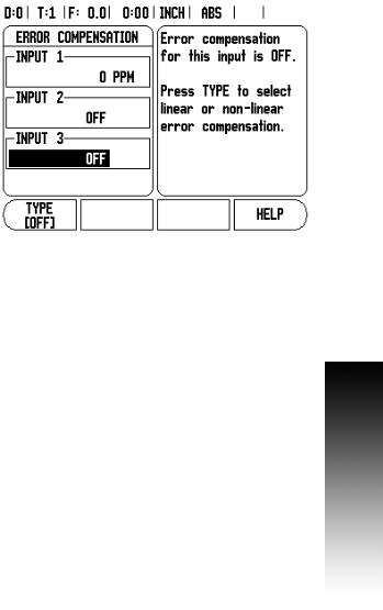
Error Compensation............................................................................................... |
59 |
Linear Error Compensation ............................................................................... |
60 |
Non-Linear Error Compensation........................................................................ |
60 |
Setup procedure for Non-linear Error ................................................................ |
61 |
Starting a Non-Linear Error Compensation Table.............................................. |
62 |
Configuring the Compensation Table................................................................ |
63 |
Automatic Non Linear error compensation ....................................................... |
63 |
Backlash Compensation ........................................................................................ |
65 |
Counter Settings.................................................................................................... |
65 |
Diagnostics ............................................................................................................ |
66 |
Keypad Test ...................................................................................................... |
66 |
Edge Finder Test............................................................................................... |
66 |
Display Test ...................................................................................................... |
66 |
200S |
xi |
II - 2 Data Interface |
|
|
|
Serial Port .............................................................................................................. |
68 |
II - 3 Installation and Electrical Connections |
|
|
|
Installation.............................................................................................................. |
69 |
|
Electrical requirements ..................................................................................... |
69 |
|
Environmental................................................................................................... |
69 |
|
Preventative maintenance ................................................................................ |
69 |
II - 4 |
I/O Connections |
|
|
Wiring the Serial communication cable ................................................................. |
71 |
|
Signal ................................................................................................................ |
71 |
|
External Operations via RS-232 Data Interface................................................. |
72 |
II - 5 |
Remote Switch Data Output |
|
|
Data output using external signals.................................................................... |
73 |
|
Data output using Edge Finder ......................................................................... |
75 |
II - 6 |
Error Messages |
|
|
............................................................................................................................... |
78 |
II - 7 |
Dimensions |
|
|
DRO Dimensions ................................................................................................... |
80 |
xii

Operating Instructions
200S |
1 |
I - 1 Fundamentals of Positioning
I - 1 Fundamentals of Positioning
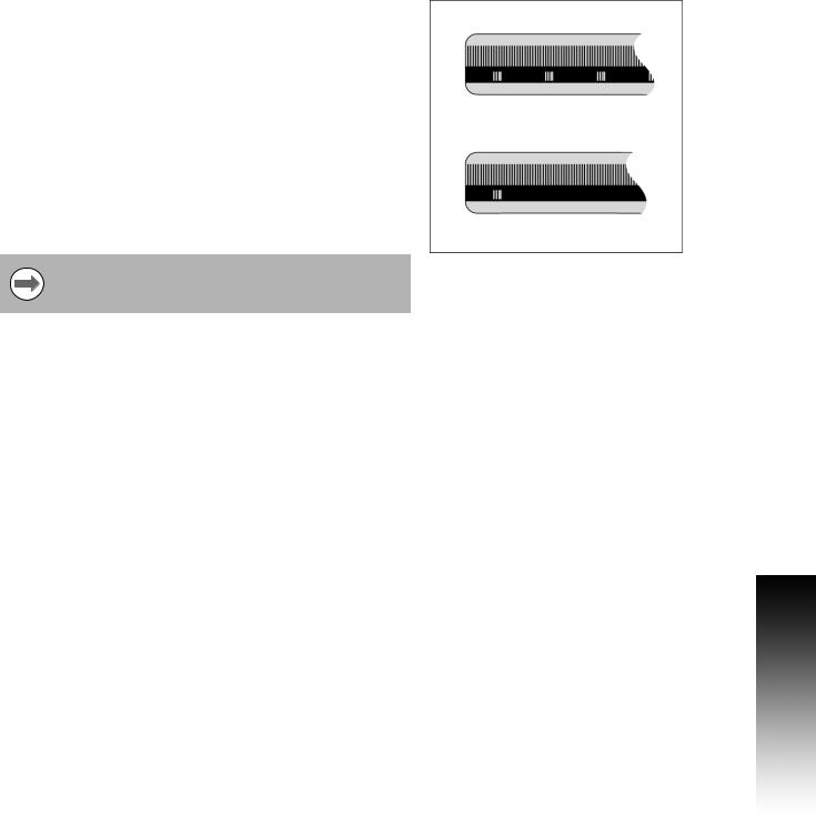
Datums
The workpiece drawing identifies a certain point on the workpiece (example: “a corner”) as the absolute datum, and perhaps one, or more other points as relative datums.
The datum setting procedure establishes these points as the origin of the absolute, or relative coordinate systems. The workpiece, which is aligned with the machine axes, is moved to a certain position relative to the tool. The display is set either to zero, or to another appropriate value (e.g., to compensate for tool radius).
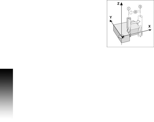
Actual Position, Nominal Position, and
Distance-To-Go
The position of the tool at any given moment is called the ACTUAL POSITION I, while the position that the tool is to move to is called the NOMINAL POSITION S. The distance from the nominal position to the actual position is called the DISTANCE-TO-GO R.
2 |
I |
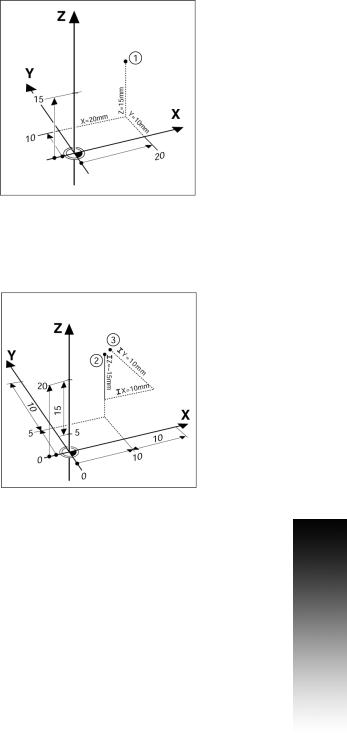
Absolute Workpiece Positions
Each position on the workpiece is uniquely identified by its absolute coordinates.
Example: Absolute coordinates of position 1:
X = 20 mm
Y = 10 mm
Z = 15 mm
If you are drilling, or milling a workpiece according to a workpiece drawing with absolute coordinates, the tool is moving to the value of the coordinates.
Incremental workpiece positions
A position can also be referenced to the preceding nominal position. In this case the relative datum is always the last nominal position. Such coordinates are referred to as incremental coordinates (increment = increase). They are also called incremental, or chain dimensions, since the positions are defined as a chain of dimensions. Incremental coordinates are designated with the prefix I.
Example: Incremental coordinates of position 3 referenced to position 2.
Absolute coordinates of position 2:
X = 10 mm
Y = 5 mm
Z = 20 mm
Incremental coordinates of position 3:
IX = 10 mm
IY = 5 mm
IZ = 20 mm
If you are drilling, or milling a workpiece according to a drawing with incremental coordinates, you are moving the tool by the value of the coordinates.
I - 1 Fundamentals of Positioning
200S |
3 |
I - 1 Fundamentals of Positioning
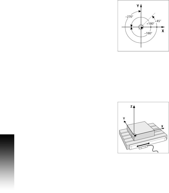
Zero Angle Reference Axis
The Zero Angle Reference Axis is the 0.0° position. It is defined as one of the two axes in the plane of rotation. The following table defines the Zero Angle where the position of the angle is zero for the three possible planes of rotation.
For angular positions, the following reference axes are defined:
Plane |
Zero Angle Reference Axis |
XY |
+X |
|
|
YZ |
+Y |
|
|
ZX |
+Z |
|
|
Positive direction of rotation is counterclockwise if the working plane is viewed in the negative tool axis direction.
EXAMPLE: Angle in the working plane X / Y
Plane |
Zero Angle Reference Axis |
+ 45° |
... bisecting line between +X and +Y |
|
|
+/- 180° |
... negative X axis |
|
|
- 270° |
... positive Y axis |
|
|
Reading head position
The reading head position provides feed back to the 200S that converts the movement of the machine axes into electrical signals. The 200S constantly evaluates these signals, and calculates the actual positions of the machine axes, which it displays as a numerical value on the screen.
If there is an interruption in power, the calculated position will no longer correspond to the actual position. When power is restored, you can re-establish this relationship by using the reference marks on the provided on the scale. The 200S provides the Reference Mark Evaluation feature (REF).
4 |
I |
Encoder Reference Marks
Encoders normally contain one or more reference marks which the 200S Reference Mark Evaluation feature uses to re-establish datum positions after a power interruption. There are two main options available for reference marks; fixed and distance-coded.
Position Trac (Distance-coded reference marks): Encoders that have marks separated by a specific encryption pattern allows the 200S to use any two pair of marks along the length of the encoder to reestablish the prior datums. This configuration means that the operator only has to travel less than two inches any where along the encoder, to re-establish the datums when the 200S is turned back on.
Fixed reference marks: Encoders that have one or more marks on fixed intervals, have to re-establish the datums correctly. It is necessary to use the same exact reference mark, during the Reference Mark Evaluation routine, that was used when the datum was first established.
The established datums’ cannot be restored from one power cycle to the next if the reference marks were not crossed before the datums were set
I - 1 Fundamentals of Positioning
200S |
5 |
I - 2 General Operations for 200S
I - 2 General Operations for 200S
Screen Layout
|
1 |
2 |
3 |
4 |
5 |
61 |
7 |
8 |
1 |
Datum |
|
|
|
|
|
|
|
2 |
Tool |
|
|
|
|
|
10 |
|
|
|
|
|
|
|
|
|
3Feed Rate
4Job Clock
5Unit of Measure
6 |
Operating Modes |
12 |
|
|
|
|
|
|
|
|
|
|
|
7 |
Page Indicator |
9 |
||||
8 |
Set/Zero |
|
|
|
|
|
9 |
Axis Labels |
|
|
|
|
|
13 |
|
|
||||
10 |
Ref Symbol |
|
|
|
|
|
11 |
Soft key Labels |
|
|
|
|
|
12 |
Display Area |
|
|
|
|
|
13 |
Near Zero Warning (In Distance-To-Go mode only) |
11 |
|
|||
|
|
|
||||
The ACU-RITE 200S readout provides application-specific features that allows you to obtain the most productivity from your manual machine tools.
Status Bar - This displays the current datum, tool, feed rate, job clock time, unit of measure, operating mode status, page indicator, and set/zero. See Job Setup for details on setting up the Status Bar parameters.
Display Area - Indicates the current position of each axis. Also shows forms, fields, instruction boxes, error messages and help topics.
Axis Labels - Indicates axis for corresponding axis key.
Ref Symbols - Indicates current reference mark status.
Soft key Labels - Indicates the various milling or turning functions.
6 |
I |
General Navigation
Use key pad to enter numeric values within each field.
The ENTER key will confirm the entry within a field, and return to the previous screen.
Press the C key to clear entries, and error messages, or return back to the previous screen.
SOFT KEY labels show the various milling, or turning functions. These functions are selected by pressing the corresponding soft key directly below each soft key label. There are 3 pages of selectable soft key functions. These are accessed using the LEFT or RIGHT arrow keys as indicated below.
LEFT or RIGHT arrow keys move through pages 1-3 of soft key selectable functions. The current page will be highlighted in the Status bar at the top of screen.
Use the UP, or DOWN arrow keys to move between fields within a form, and list boxes within a menu. The orientation of the cursor is such that it will return to the top once it has reached the bottom of a menu.
General Overview
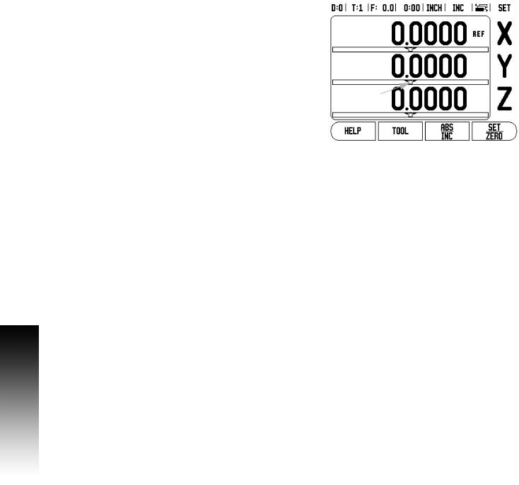
Graphic Positioning Aid
When traversing to display value zero (in the Distance-To-Go mode), 200S displays a graphic positioning aid.
200S displays the graphic positioning aid in a narrow rectangle underneath the currently active axis. Two triangular marks in the center of the rectangle symbolize the nominal position.
A small square symbolizes the axis slide. An arrow indicating the direction appears in the square while the axis is moving towards, or away from the nominal position. Note that the square does not begin to move until the axis slide is near the nominal position. Setting up the graphic positioning aid, see "Status Bar Settings" on page 15 under Job Setup.
I - 2 General Operations for 200S
200S |
7 |
I - 2 General Operations for 200S
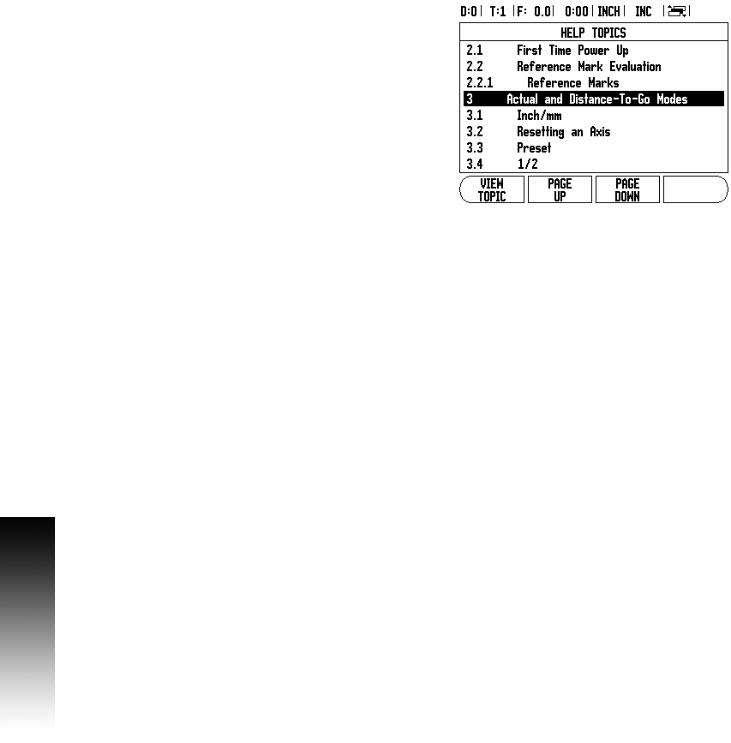
Help Screen
The integrated operating instructions provide information and assistance in any situation.
To call the operating instructions:
8Press the HELP soft key.
8Information relevant to the current operation will be displayed.
8Use the UP/DOWN arrow keys if the explanation is spread over more than one screen page.
To view information on another topic:
8Press the LIST OF TOPICS soft key.
8Press the UP/DOWN arrow keys to scroll through the index.
8Press the ENTER key to select the item you need.
To exit the operating instructions:
8 Press the C key.
8 |
I |
Data Input Forms
Information required for various operational functions and setup parameters are entered through a data input form. These forms will appear after selecting features that require any additional information. Each form provides specific fields for entering the required information.
Changes must be confirmed by pressing the ENTER key for them to become effective. If you do not want to save your changes, press the C key to return to the previous screen without saving changes.
In some cases such as the Tool Table, the C key is used in place of the ENTER key.
Instruction Box messages
Whenever a Menu, or Form is opened, an instruction box will also open immediately to the right of it. This message box will provide information for what the chosen function does, and present instructions for available options.
Error Messages
If an error occurs while working with the 200S, the message will appear on the display, and provide an explanation of what caused the error. See "Error Messages" on page 78.
To clear the error message:
8 Press the C key.
Error message will be cleared, and normal operation can be continued.
I - 2 General Operations for 200S
200S |
9 |

I - 2 General Operations for 200S
Power Up
Switch on the power (located on the back). The initial screen will appear. This screen will only appear the very first time the unit is powered up. The following steps may have already been completed by
the installer.
Select the proper language by pressing the LANGUAGE soft key.
Choose your application of either MILL or TURN. The APPLIC. [MILL/TURN] soft key toggles between these two settings.
Next, select the number of axes required. When complete, press the ENTER hard key.
If necessary, you can change the application later in Installation Setup under Counter Settings.
The 200S is now ready for the remaining setup requirements. It is now in the operating mode “Absolute”. Each active axis will have a flashing“REF”sign next to it. The following section, “Reference Mark Evaluation”, describes setting up this feature.
Reference Mark Evaluation |
|
|
The 200S reference mark evaluation feature (1), automatically |
|
|
re-establishes the relationship between axis slide positions and |
|
|
display values that was last defined by setting the datum. |
|
|
(1) |
||
|
||
For each axis with an encoder that has reference marks, the “REF” |
|
|
indicator will flash for that axis. After crossing over the reference |
|
|
marks, the indicator will stop flashing and change to a non-flashing |
|
|
“REF” indicator. |
|
|
Working without reference mark evaluation |
|
|
The 200S can also be used without crossing over the reference marks. |
|
|
8 Press the NO REF soft key to exit the reference mark evaluation |
|
|
routine, and continue. |
|
10 |
I |

The 200S can still cross over reference marks at a later time. Such as if it becomes necessary to define a datum that can be re-established after a power interruption.
8Press the ENABLE REF soft key to activate the position recovery routine. Press the RIGHT / LEFT arrow key if the soft key is not shown on current screen.
If an encoder is setup without reference marks, then the REF indicator will not be displayed, and a datum set from any axis will be lost once power is turned off.
Enable/Disable Ref function
The ENABLE/DISABLE soft key, that is present during the position recovery routine, allows the operator to select a specific reference mark on an encoder. This is important when using encoders with Fixed Reference Marks (instead of ones with Position-Trac™ feature). When the DISABLE REF soft key is pressed, the recovery routine is paused and any reference marks that are crossed during encoder movement are ignored. When the ENABLE REF soft key is then pressed, the recovery routine once again becomes active and the next crossed reference mark will be selected.
Not all reference marks have to be crossed over on each encoder, only those that are needed.
8Once reference marks for all desired axes are established, press the NO REF soft key to cancel out of the routine. If all reference marks have been found, the 200S will return to the DRO display
screen automatically.
I - 2 General Operations for 200S
200S |
11 |
I - 2 General Operations for 200S
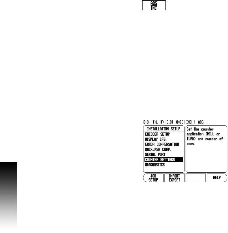
Operating Modes
The 200S has two operating modes: Distance-To-Go (INCREMENTAL), and Actual Value (ABSOLUTE). The Actual Value mode always displays the current actual position of the tool, relative to the active datum. In this mode, all moves are done by traveling until the display matches the nominal position that is required. The Distance-To-Go feature enables you to approach nominal positions by traversing to display value zero. When working within the Distance-To- Go mode you can enter nominal coordinates as either absolute or incremental dimensions.
Milling applications have only the tool length offsets active while in the Actual Value Mode. In the Distance-To-Go mode, both the diameter and length offsets are used to calculate the amount of “distance-to- go” required to get to the desired nominal position. This is relative to the edge of the tool that will be doing the cutting.
Turning applications have both diameter and length offsets in both the Actual Value and Distance-To-Go modes.
Press the ABS/INC soft key to toggle between these two modes. To view other soft key functions in either Actual Value or Distance-To-Go mode, use the LEFT/RIGHT arrow keys.
The Turning application provides a quick method for coupling the Z axes positions on a 3 axis system. For more information, see "Z Coupling" on page 52.
Setup
200S offers two categories for setting up operating parameters. These categories are: Installation Setup and Job Setup. The Job Setup parameters are used to accommodate specific machining requirements for each job. Installation Setup is used to establish encoder, display and communication parameters.
The Installation Setup menu is accessed by pressing the SETUP soft key, then the INSTALLATION SETUP soft key. When in the Installation Setup menu, the following soft keys will be available:
JOB SETUP: Press to begin accessing the Job Setup parameters.
IMPORT/EXPORT: Press to begin importing or exporting operating parameters. See "Import/Export" on page 18.
HELP: Will open on-line help.
8To view, and change Installation Setup parameters, first press the SETUP soft key, then the INSTALLATION SETUP soft key.
8Use the UP/DOWN arrow keys to highlight the parameters of interest.
8press the ENTER key.
12 |
I |
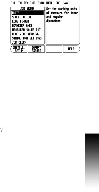
Job Setup Parameters
8To view and change Job Setup parameters, first press the SETUP soft key.
8Use the UP/DOWN arrow keys to highlight the parameters of interest.
8press the ENTER key.
The Job Setup Data can be imported, or exported using the IMPORT/EXPORT soft key.
Exporting the current Job Setup:
8Press the SETUP soft key.
8Press the IMPORT/EXPORT soft key.
8Press the EXPORT soft key.
Importing a new Job Setup Table
8Press the SETUP soft key.
8Press the IMPORT/EXPORT soft key.
8Press the IMPORT soft key.
Units
The Units form is used to specify the preferred display units and format. You can also select the unit of measure by pressing the INCH/MM soft key in either Actual Value or Distance-To-Go mode.
Scale Factor
The scale factor may be used to scale the part up or down. A scale factor of 1.0 creates a part with the exact size as dimensioned on the print. A scale factor >1 “grows” the part, and <1 “shrinks” the part.
The numeric keys are used to enter a number greater than zero. The number range is 0.1000 to 10.000. A negative value may also
be entered.
The scale factor settings will be retained on a power cycle.
When the scale factor is a value other than 1, the scaling symbol is shown on the axis display.
The ON/OFF soft key is used to disable the current scale factors.
I - 2 General Operations for 200S
200S |
13 |
I - 2 General Operations for 200S
Mirror
A scale factor of -1.00 will produce a mirror image of the part. You can both mirror and scale a part at the same time.
Edge Finder (milling applications only)
The diameter, length offset and units of the edge finder are set in this form. Both values are in the units indicated in the form. Please see "Probing Functions for Datum Setting" on page 27 for details on using Edge Finder functions.
The numeric keys are used to enter values of diameter and length. The diameter must be greater than zero. The length is a sign value (negative, or positive).
A soft key is provided to indicate the units of measure for the edge finder.
The edge finder values will be retained on a power cycle.
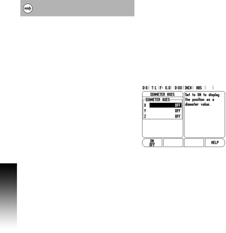
Diameter Axes
Select Diameter Axes to bring up the diameter screen shown here to set which axes can be displayed in either radius or diameter values. ON indicates that the axis position will be displayed as a diameter value. When OFF, the Radius/Diameter feature does not apply. For turning applications see "Radius/Diameter Soft Key" on page 51 for the Radius/Diameter feature.
8Cursor to Diameter Axes, and press ENTER.
8The cursor will be in the X axis field. Depending on the parameter you need for that axis press ON/OFF soft key to turn feature on or off.
8Press ENTER.
14 |
I |

Measured Value Output
With the measured value output feature, probe measurement values can be sent over the serial port. Also output of the current display positions is activated via a command (Ctrl B), sent to the 200S over the serial port.
The Measured Value Output form is used to set data output during probing operations.
Data Output Probing (Milling Only), may be set to either On, or Off. When On, the measurement data is output when the probe operation is completed.
Refer to chapter "II - 5 Remote Switch Data Output on page 73” for information on the format of the output data.
Near Zero Warning
The Near Zero Warning form, is used to configure the bar graph. This is shown below the axes’ display in Distance-To-Go mode. Each axis has its own range.
8Press the ON/OFF soft key to enable, or begin entering values using the numeric keys. The current position box will begin moving when the position is within range.
Status Bar Settings
The Status Bar is the segmented bar at the top of the screen which displays current datum, tool, feed rate, job clock and page indicator.
8Press the ON/OFF soft key for each setting you want to see displayed.
I - 2 General Operations for 200S
200S |
15 |

I - 2 General Operations for 200S
Job Clock
The job clock shows the hours (h), minutes (m), seconds (s). It operates like a stop watch showing elapsed time. The clock starts timing from 0:00:00.
The elapsed time field shows the total accumulated time from each interval.
8Press the START/STOP soft key, the status field will read RUNNING. Press it again to stop time from elapsing.
8Press RESET to reset the elapsed time. Resetting will stop the clock if it is running.
Pressing the Decimal key while in operating mode, will also stop and start the clock. Pressing the Zero key will reset the clock.
16 |
I |
Loading...