


Instruction Manual
Weather Thermometer
models 00754/00771W/00772W/00773W/00774W
CONTENTS |
|
Set the Time, Date & Units....... |
6 |
Unpacking Instructions............ |
2 |
Placement Guidelines.............. |
7 |
Package Contents................... |
2 |
Using the Thermometer........... |
8 |
Product Registration................ |
2 |
Troubleshooting...................... |
9 |
Features & Benefits: Sensor..... |
2 |
Care & Maintenance............. |
10 |
Features & Benefits: Display.... |
3 |
Replace Intelli-Time® battery... |
10 |
Setup..................................... |
4 |
Specifications........................ |
10 |
Sensor Setup.......................... |
4 |
FCC Information.................... |
10 |
Display Setup......................... |
5 |
Customer Support.................. |
11 |
Intelli-Time® Clock................... |
6 |
Warranty.............................. |
11 |
Questions? Contact Customer Support at (877) 221-1252 or visit www.AcuRite.com.
SAVE THIS MANUAL FOR FUTURE REFERENCE.
Congratulations on your new AcuRite product. To ensure the best possible product performance, please read this manual in its entirety and retain it for future reference.
Unpacking Instructions
Remove the protective film that is applied to the LCD screen prior to using this product. Locate the tab and peel off to remove.
Package Contents
1. Display unit
2. Outdoor sensor
3. Instruction Manual
|
IMPORTANT |
TO RECEIVE WARRANTY SERVICE |
|||||||
|
|
|
|
|
|
|
|
PRODUCT MUST BE REGISTERED |
|
|
|
|
|
|
|
|
|
|
|
|
PRODUCT REGISTRATION |
|
|
||||||
|
|
Register online |
|
|
|||||
|
|
to receive 1 year |
|
|
|||||
|
|
warranty protection |
|
► |
|||||
www.AcuRite.com |
|
||||||||
|
|
|
|
|
|
|
|
|
Register a Product |
Features & Benefits |
OUTDOOR SENSOR |
||||||||
1 |
|
|
|
|
|
|
|
||
|
|
|
|
|
|
|
|||
2 |
|
|
|
|
|
|
|
1. |
Integrated Hanger |
|
|
|
|
|
|
|
|
For easy placement. |
|
|
|
|
|
|
|
|
|
|
|
5 |
2. |
Wireless Signal Indicator |
|||||||
|
|
|
|
|
|
|
|
|
Flashes when data is being sent to the |
|
|
|
|
|
|
|
|
|
display unit. |
3 |
|
|
|
|
|
|
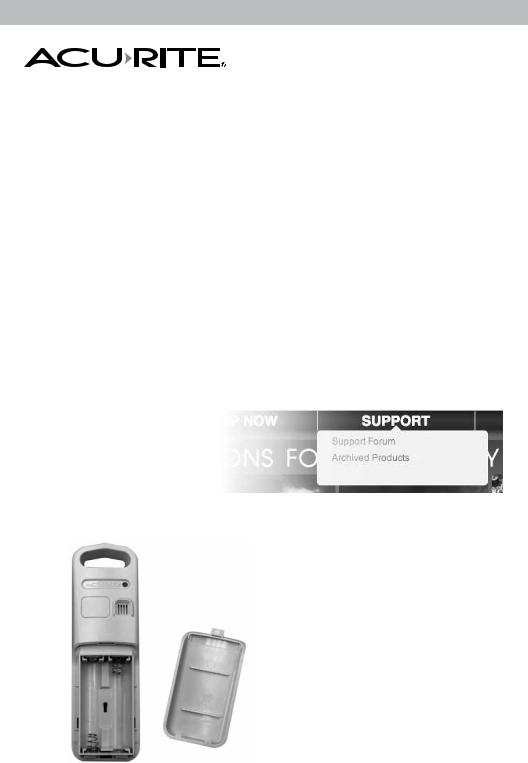
|
3. |
Battery Compartment |
|
|
|
|
|
|
|
4. |
A-B-C Switch |
|
|
|
|
|
|
|
|
|||
|
|
|
|
|
|
|
|
||
4 |
|
|
|
|
|
|
|
|
ID code that must match display’s A-B-C |
|
|
|
|
|
|
|
|
switch to ensure units synchronize. |
|
|
|
|
|
|
|
|
|
|
|
|
|
|
|
|
|
|
|
5. |
Battery Compartment Cover |
2
Features & Benefits
1
|
|
|
|
|
|
|
14 |
|||||
2 |
|
|
|
|
|
|
13 |
|||||
|
|
|
|
|
|
|||||||
3 |
|
|
|
|
|
|
12 |
|||||
|
|
|
|
|
|
|||||||
4 |
|
|
|
|
|
|
11 |
|||||
|
|
|
|
|
|
|
|
|
|
|
10 |
|
5 |
|
|
|
|
|
|
|
|
|
|
||
|
|
|
|
|
|
|
|
|
||||
|
|
|
|
|
|
|
|
|
|
|
|
|
6 |
|
|
|
|
|
|
|
|
|
|
|
|
|
|
|
|
|
|
|
|
|
|
|
|
|
7 |
|
|
|
|
|
|
|
|
9 |
|||
|
|
|
|
|
|
|
|
|
||||
|
|
|
|
|
|
|
|
|
|
|
8 |
|
|
|
|
|
|
|
|
|
|
|
|
||
|
|
|
|
|
|
|
|
|
|
|
||
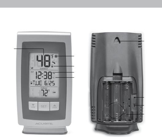
DISPLAY UNIT
1.Current Outdoor Temperature
Arrow icon indicates the direction the temperature is trending.
2.Outdoor Sensor Signal Strength
3.Daylight Saving Time Indicator
Shown only during setup.
4.Display Low Battery Indicator
5.Day of the Week
6.Current Indoor Temperature
Arrow icon indicates the direction the temperature is trending.
7.“▼“ Button
8.“SET“ Button
9.“▲“ Button
10. Date
11. Selected Time Zone
15
16
17
18
12. Intelli-Time® Clock
13. Outdoor Sensor Low Battery
Indicator
14.Freeze Alert Indicator
Indicates temperature is below freezing (32°F; 0°C).
15.Integrated Hang Hole
For easy wall mounting.
16.Reset
Full reset to factory default.
17.A-B-C Switch
ID code that must match sensor’s A-B-C switch to ensure units synchronize .
18.Battery Compartment
19.Battery Compartment Cover
(Not shown)
3

SETUP
Sensor Setup
1Set the A-B-C Switch
The A-B-C switch is located inside the battery compartment. It can be set to A, B or C. However, you must select the same letter choices for both the sensor and the display unit in order for the units to synchronize.
2Install or Replace Batteries
AcuRite recommends high quality alkaline or lithium batteries for the best product performance. Heavy duty or rechargeable batteries are not recommended.
The sensor requires lithium batteries in low temperature
2 |
Install Batteries |
|
|
||||||||
|
2 AA batteries |
|
|
||||||||
|
|
|
|
|
|
|
|
|
|
|
|
|
|
|
|
|
|
|
|
|
|
|
|
|
|
|
|
|
|
|
|
|
|
|
|
|
|
|
|
|
|
|
|
|
|
|
|
|
|
|
|
|
|
|
|
|
|
|
|
|
|
|
|
|
|
|
|
|
|
|
|
|
|
|
|
|
|
|
|
|
|
|
|
|
|
|
|
|
|
|
|
|
|
|
|
|
|
|
|
|
|
|
|
|
|
|
|
|
|
|
|
|
|
|
|
|
|
|
|
|
|
|
|
|
|
|
|
|
|
|
|
|
|
|
|
|
|
|
|
|
|
|
|
|
|
|
|
|
|
|
|
|
|
|
|
|
|
|
|
|
|
|
|
|
|
|
|
|
|
|
|
|
|
|
|
|
|
|
|
|
|
|
|
|
|
|
|
|
|
|
|
conditions. Cold temperatures can cause alkaline batteries to function improperly. Use
lithium batteries in the sensor for temperatures below -4ºF / -20ºC.
1.Slide off the battery compartment cover. Take note of the A-B-C switch setting inside the battery compartment.
2.Insert 2 x AA batteries into the battery compartment, as shown. Follow the polarity (+/-) diagram in the battery compartment.
3.Replace the battery cover.
1A-B-C Switch set to match display unit
4
 Loading...