


CONGRATULATIONS!
You have just purchased MILLPWR by ACU-RITE, a versatile and flexible 2-axis Control/
3-axis Readout system that effectively combines powerful features and functionality with ease of use at an affordable price.
MILLPWR satisfies the needs of the milling market where manual and automated operation are both useful and needed. MILLPWR also maximizes your throughput by significantly reducing set-up time, scrap and other non-productive operations thereby increasing your efficiency, productivity and profitability.
MILLPWR is designed and manufactured in the United States at ACU-RITE’s ISO-9001 registered facility. MILLPWR is a complete system that includes ground and hardened ball screws, powerful DC servo motors, a user friendly operator console with a built-in floppy disk drive, a controller cabinet containing an electronics module (which includes a large hard disk drive) and a motor control module. The system is closed-looped with positioning feedback provided by the use of ACU-RITE’s precision glass scales (2µm/.0001” resolution).
MILLPWR utilizes a conversational, menu prompted format that makes it easy for you to learn and quick for you to program. No prior programming experience or training is necessary. All you have to do is simply enter part dimensions directly from the print. MILLPWR automatically calculates the tool path... with immediate part view graphic feedback providing program verification. MILLPWR’s intuitiveness allows you to learn how to operate MILLPWR and begin making parts, and profits, in a matter of hours.
MILLPWR is backed by a comprehensive 1-year warranty, with nationwide support provided by a factory trained and certified distribution network.
Thank you for choosing ACU-RITE. We’re confident you’ll be more than glad you did.
Sincerely,
ACU-RITE INC.

MILLPWR System Setup Access Code
An access code must be entered before the system setup parameters can be set or changed. This prevents inadvertently resetting parameters.
IMPORTANT
The access code is 8891
Refer to section 7, “System Setup.”
IMPORTANT
Supervisors may wish to remove this page from the MILLPWR manual after initially setting up the system parameters. Keep it in a safe place for future use.
387900-970 Edition E

TABLE OF CONTENTS
Section 1. Introduction |
|
|
System Overview........................................................................... |
|
1-1 |
Machine Layout ................................................................... |
|
1-1 |
Keypad Layout .................................................................... |
|
1-3 |
Screen Layout ...................................................................... |
|
1-4 |
Saving, Backing Up, and Creating Directories |
|
|
For Programs............................................................... |
|
1-5 |
Emergency Table Stop Button .............................................. |
|
1-5 |
Conventions .................................................................................. |
|
1-6 |
Axis Conventions .................................................................... |
|
1-6 |
Absolute/Incremental ............................................................... |
|
1-7 |
Section 2. DRO |
|
|
Start-up ........................................................................................ |
|
2-1 |
Power Up ............................................................................ |
|
2-1 |
Finding Home ...................................................................... |
|
2-2 |
DRO Functions ............................................................................. |
|
2-3 |
Reset an Axis ....................................................................... |
|
2-3 |
Inch-Metric .......................................................................... |
|
2-3 |
Move Table ......................................................................... |
|
2-3 |
Establishing a Datum ............................................................ |
|
2-4 |
Using a Probe ...................................................................... |
|
2-5 |
One Time Milling Functions .................................................. |
|
2-6 |
Section 3. Programming |
|
|
Programming Considerations ......................................................... |
|
3-1 |
Depth of Cut ........................................................................ |
|
3-1 |
Tool Offset .......................................................................... |
|
3-1 |
“From” and “To” Points ....................................................... |
|
3-2 |
Datum Selection ................................................................... |
|
3-2 |
Absolute and Incremental Dimensions ................................... |
3-2 |
|
|
|
|
Operation Manual |
i |
MILLPWR |

TABLE OF CONTENTS
Continuous Milling ................................................................ |
3-3 |
Creating a Program ....................................................................... |
3-4 |
The View Key ..................................................................... |
3-6 |
Running a Program ........................................................................ |
3-6 |
Setting the Datum ................................................................. |
3-6 |
Testing Your Program .......................................................... |
3-7 |
Pressing the GO Key ........................................................... |
3-8 |
Feed Rate Override ............................................................. |
3-9 |
Machining to Zero ................................................................ |
3-9 |
Program Functions ...................................................................... |
3-11 |
Accessing the Load, Save, Delete, and |
|
Backup Options ........................................................ |
3-11 |
Saving a Program ............................................................... |
3-12 |
Directories ......................................................................... |
3-14 |
Creating a Directory .................................................. |
3-14 |
Selecting a Directory ................................................. |
3-17 |
Deleting a Directory .................................................. |
3-19 |
Other Program Functions ................................................... |
3-20 |
Naming a Program .................................................... |
3-20 |
Deleting a Program .................................................... |
3-21 |
Backing Up a Program .............................................. |
3-22 |
Loading a Program .................................................... |
3-24 |
From MILLPWR’s internal hard disk drive .......... |
3-24 |
From a 3 ½” floppy disk ..................................... |
3-26 |
From your PC ..................................................... |
3-27 |
Section 4. Demonstration |
|
A Demonstration Program ............................................................. |
4-1 |
Selecting the Datum .............................................................. |
4-1 |
Beginning the Program .......................................................... |
4-1 |
Selecting a Tool ................................................................... |
4-2 |
Milling the Workpiece Contour ............................................. |
4-3 |
MILLPWR
ii |
Operation Manual |
|
|
TABLE OF CONTENTS |
Programming the Bolt Circle |
............................................... |
4-13 |
Programming the Pocket .................................................... |
|
4-15 |
Saving Your Program ......................................................... |
|
4-17 |
Testing Your Program ........................................................ |
|
4-17 |
Running the Program .......................................................... |
|
4-18 |
Tool Changes ..................................................................... |
|
4-20 |
Clearing the Program .......................................................... |
|
4-20 |
Section 5. Program Steps |
|
|
Sample Milling and Drilling ............................................................ |
|
5-1 |
Set Tool ............................................................................... |
|
5-1 |
Positioning/Drill .................................................................... |
|
5-1 |
Mill Line .............................................................................. |
|
5-2 |
Mill Arc ............................................................................... |
|
5-2 |
Blend ................................................................................... |
|
5-3 |
Rectangular Milling Functions ........................................................ |
|
5-4 |
Pocket ................................................................................. |
|
5-4 |
Rectangular Frame ............................................................... |
|
5-5 |
Face .................................................................................... |
|
5-6 |
Slot ...................................................................................... |
|
5-7 |
Circular Milling Functions .............................................................. |
|
5-8 |
Circular Pocket .................................................................... |
|
5-8 |
Circular Frame ..................................................................... |
|
5-9 |
Ring ................................................................................... |
|
5-10 |
Hole Patterns .............................................................................. |
|
5-11 |
Row of Holes ..................................................................... |
|
5-11 |
Hole Frame and Hole Array ............................................... |
|
5-12 |
Bolt Circle ......................................................................... |
|
5-13 |
More Steps ................................................................................. |
|
5-14 |
Repeat ............................................................................... |
|
5-14 |
Rotate ................................................................................ |
|
5-15 |
Mirror ................................................................................ |
|
5-16 |
|
|
|
Operation Manual |
iii |
MILLPWR |

TABLE OF CONTENTS
Custom Pocket .................................................................. |
5-17 |
Engrave ............................................................................. |
5-18 |
Explode ............................................................................. |
5-20 |
Section 6. Calculator |
|
Four Function Arithmetic ............................................................... |
6-1 |
Trig and Math Functions ................................................................ |
6-1 |
Geometry Calculator ..................................................................... |
6-4 |
Why We Need a Geometry Calculator ................................. |
6-4 |
Working with the Geometry Calculator ................................. |
6-5 |
Example Problem .......................................................................... |
6-7 |
Strategy ............................................................................... |
6-7 |
Starting the Program ............................................................. |
6-7 |
Entering the Lines ................................................................. |
6-8 |
Finding the Arc .................................................................. |
6-10 |
Finding the Points of Tangency ........................................... |
6-12 |
Returning Features .............................................................. |
6-13 |
Section 7. Setup |
|
Inch or Metric ...................................................................... |
7-1 |
Operator Setup ............................................................................. |
7-2 |
Tool Library .................................................................................. |
7-2 |
Scale Factor ................................................................................. |
7-3 |
Display Options ............................................................................ |
7-4 |
Touch Probe ................................................................................. |
7-5 |
Feed Rate Settings ........................................................................ |
7-5 |
System Setup ................................................................................ |
7-6 |
Protection ............................................................................ |
7-6 |
Error Compensation ............................................................. |
7-7 |
Encoder Direction ................................................................ |
7-8 |
Serial Port ............................................................................ |
7-9 |
MILLPWR
iv |
Operation Manual |

|
TABLE OF CONTENTS |
Section 8. Remote Storage |
|
Equipment ..................................................................................... |
8-1 |
Choosing a Serial Cable ................................................................ |
8-1 |
Connecting MILLPWR to Your PC ............................................... |
8-2 |
Installing the Remote Storage Program ........................................... |
8-3 |
Operation Manual |
v |
MILLPWR |

TABLE OF CONTENTS
Setting the PC’s COM Port and BAUD Rates ............................... |
8-4 |
Common Error Messages .............................................................. |
8-5 |
Section 9. Troubleshooting Guide |
|
Introduction .................................................................................. |
9-1 |
Using the Table ............................................................................. |
9-1 |
Table ............................................................................................ |
9-2 |
MILLPWR
vi |
Operation Manual |

TABLE OF CONTENTS
387900-167 Software Version 1.3 Ed G
Operation Manual |
vii |
MILLPWR |
INTRODUCTION
MILLPWR
INTRODUCTION
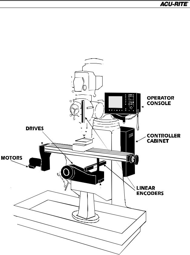
System Overview
Machine Layout
|
|
|
|
|
|
|
|
|
|
|
|
|
|
|
|
|
|
|
|
|
|
|
|
|
|
|
|
|
|
|
|
|
|
|
|
|
|
|
|
|
|
|
|
|
|
|
|
|
|
|
|
|
|
|
|
|
|
|
|
|
|
|
|
|
|
|
|
|
|
|
|
|
|
|
|
|
|
|
|
|
|
|
|
|
|
|
|
|
|
|
|
|
|
|
|
|
|
|
|
|
|
|
|
|
|
|
|
|
|
|
|
|
|
|
|
|
|
|
|
|
|
|
|
|
|
|
|
|
|
|
|
|
|
|
|
|
|
|
|
|
|
|
|
|
|
|
|
|
|
|
|
|
|
|
|
|
|
|
|
|
|
|
|
|
|
|
|
|
|
|
|
|
|
|
|
|
|
|
|
|
|
|
|
|
|
|
|
|
|
|
|
|
|
|
|
|
|
|
|
|
|
|
|
|
|
|
|
|
|
|
|
|
|
|
|
|
|
|
|
|
|
|
|
|
|
|
|
|
|
|
|
|
|
|
|
|
|
|
|
|
|
|
|
|
|
|
|
|
|
|
|
|
|
|
|
|
|
|
|
|
|
|
|
|
|
|
|
|
|
|
|
|
|
|
|
|
|
|
|
|
|
|
|
|
|
|
|
|
|
|
|
|
|
|
|
|
|
|
|
|
|
|
|
|
|
|
|
|
|
|
|
|
|
|
|
|
|
|
|
|
|
|
|
|
|
|
|
|
|
|
|
|
|
|
|
|
|
|
|
|
|
|
|
|
|
|
|
|
|
|
|
|
|
|
|
|
|
|
|
|
|
|
|
|
|
|
|
|
|
|
|
|
|
|
|
|
|
|
|
|
|
|
|
|
|
|
|
|
|
|
|
|
|
|
|
|
|
|
|
|
|
|
|
|
|
|
|
|
|
|
|
|
|
|
|
|
|
|
|
|
|
|
|
|
|
|
|
|
|
|
|
|
|
|
|
|
|
|
|
|
|
|
|
|
|
|
|
|
|
|
|
|
|
|
|
|
|
|
|
|
|
|
|
|
|
|
|
|
|
|
|
|
|
|
|
|
|
|
|
|
|
|
|
|
|
|
|
|
|
|
|
|
|
|
|
|
|
|
|
|
|
|
|
|
|
|
|
|
|
|
|
|
|
|
|
|
|
|
|
|
|
|
|
|
|
|
|
|
|
|
|
|
|
|
|
|
|
|
|
|
|
|
|
|
|
|
|
|
|
|
|
|
|
|
|
|
|
|
|
|
|
|
|
|
|
|
|
|
|
|
|
|
|
|
|
|
|
|
|
|
|
|
|
|
|
|
|
|
|
|
|
|
|
|
|
|
|
|
|
|
|
|
|
|
|
|
|
|
|
|
|
|
|
|
|
|
|
|
|
|
|
|
|
|
|
|
|
|
|
|
|
|
|
|
|
|
|
|
|
|
|
|
|
|
|
|
|
|
|
|
|
|
|
|
|
|
|
|
|
|
|
|
|
|
|
|
|
|
|
|
|
|
|
|
|
|
|
|
|
|
|
|
|
|
|
|
|
|
|
|
|
|
|
|
|
|
|
|
|
|
|
|
|
|
|
|
|
|
|
|
|
|
|
|
|
|
|
|
|
|
|
|
|
|
|
|
|
|
|
|
|
|
|
|
|
|
|
|
|
|
|
|
|
|
|
|
|
|
|
|
|
|
|
|
|
|
|
|
|
|
|
|
|
|
|
|
|
|
|
|
|
|
|
|
|
|
|
|
|
|
|
|
|
|
|
|
|
|
|
|
|
|
|
|
|
|
|
|
|
|
|
|
|
|
|
|
|
|
|
|
|
|
|
|
|
|
|
|
|
|
|
|
|
|
|
|
|
|
|
|
|
|
|
|
|
|
|
|
|
|
|
|
|
|
|
|
|
|
|
|
|
|
|
|
|
|
|
|
|
|
|
|
|
|
|
|
|
|
|
|
|
|
|
|
|
|
|
|
|
|
|
|
|
|
|
|
|
|
|
|
|
|
|
|
|
|
|
|
|
|
|
|
|
|
|
|
|
|
|
|
|
|
|
|
|
|
|
|
|
|
|
|
|
|
|
|
|
|
|
|
|
|
|
|
|
|
|
|
|
|
|
|
|
|
|
|
|
|
|
|
|
|
|
|
|
|
|
|
|
|
|
|
|
|
|
|
|
|
|
|
|
|
|
|
|
|
|
|
|
|
|
|
|
|
|
|
|
|
|
|
|
|
|
|
|
|
|
|
|
|
|
|
|
|
|
|
|
|
|
|
|
|
|
|
|
|
|
|
|
|
|
|
|
|
|
|
|
|
|
|
|
|
|
|
|
|
|
|
|
|
|
|
|
|
|
|
|
|
|
|
|
|
|
|
|
|
|
|
|
|
|
|
|
|
|
|
|
|
|
|
|
|
|
|
|
|
|
|
|
|
|
|
|
|
|
|
|
|
|
|
|
|
|
|
|
|
|
|
|
|
|
|
|
|
|
|
|
|
|
|
|
|
|
|
|
|
|
|
|
|
|
|
|
|
|
|
|
|
|
|
|
|
|
|
|
|
|
|
|
|
|
|
|
|
|
|
|
|
|
|
|
|
|
|
|
|
|
|
|
|
|
|
|
|
|
|
|
|
|
|
|
|
|
|
|
|
|
|
|
|
|
|
|
|
|
|
|
|
|
|
|
|
|
|
|
|
|
|
|
|
|
|
|
|
|
|
|
|
|
|
|
|
|
|
|
|
|
|
|
|
|
|
|
|
|
|
|
|
|
|
|
|
|
|
|
|
|
|
|
|
|
|
|
|
|
|
|
|
|
|
|
|
|
|
|
|
|
|
|
|
|
|
|
|
|
|
|
|
|
|
|
|
|
|
|
|
|
|
|
|
|
|
|
|
|
|
|
|
|
|
|
|
|
|
|
|
|
|
|
|
|
|
|
|
|
|
|
|
|
|
|
|
|
|
|
|
|
|
|
|
|
|
|
|
|
|
|
|
|
|
|
|
|
|
|
|
|
|
|
|
|
|
|
|
|
|
|
|
|
|
|
|
|
|
|
|
|
|
|
|
|
|
|
|
|
|
|
|
|
|
|
|
|
|
|
|
|
|
|
|
|
|
|
|
|
|
|
|
|
|
|
|
|
|
|
|
|
|
|
|
|
|
|
|
|
|
|
|
|
|
|
|
|
|
|
|
|
|
|
|
|
|
|
|
|
|
|
|
|
|
|
|
|
|
|
|
|
|
|
|
|
|
|
|
|
|
|
|
|
|
|
|
|
|
|
|
|
|
|
|
|
|
|
|
|
|
|
|
|
|
|
|
|
|
|
|
|
|
|
|
|
|
|
|
|
|
|
|
|
|
|
|
|
|
|
|
|
|
|
|
|
|
|
|
|
|
|
|
|
|
|
|
|
|
|
|
|
|
|
|
|
|
|
|
|
|
|
|
|
|
|
|
|
|
|
|
|
|
|
|
|
|
|
|
|
|
|
|
|
|
|
|
|
|
|
|
|
|
|
|
|
|
|
|
|
|
|
|
|
|
|
|
|
|
|
|
|
|
|
|
|
|
|
|
|
|
|
|
|
|
|
|
|
|
|
|
|
|
|
|
|
|
|
|
|
|
|
|
|
|
|
|
|
|
|
|
|
|
|
|
|
|
|
|
|
|
|
|
|
|
|
|
|
|
|
|
|
|
|
|
|
|
|
|
|
|
|
|
|
|
|
|
|
|
|
|
|
|
|
|
|
|
|
|
|
|
|
|
|
|
|
|
|
|
|
|
|
|
|
|
|
|
|
|
|
|
|
|
|
|
|
|
|
|
|
|
|
|
|
|
|
|
|
|
|
|
|
|
|
|
|
|
|
|
|
|
|
|
|
|
|
|
|
|
|
|
|
|
|
|
|
|
|
|
|
|
|
|
|
|
|
|
|
|
|
|
|
Operation Manual |
|
|
|
|
|
|
|
|
|
|
|
|
|
|
|
|
|
|
|
|
|
|
|
|
|
|
|
|
|
|
Page 1-1 |
||||||

INTRODUCTION
MILLPWR
Front View of Operator Console
|
INFO |
TOOL |
RECT |
CIRCLE |
HOLES |
|
|
|
|
|
|
|
SET |
POS |
LINE |
ARC |
BLEND |
|
|
|
|
|
|
|
UP |
|
|
|
|
Floppy |
|
|
|
|
|
diskette inside |
|
INC |
|
|
|
|
VIEW |
ABS |
|
|
CALC |
|
|
|
|
||
|
PGM |
7 |
8 |
9 |
/ |
|
Keypad |
|
|
|
|
|
DRO |
4 |
5 |
6 |
X |
|
CANCEL |
1 |
2 |
3 |
- |
Emergency |
Softkeys |
. |
0 |
+/- |
+ |
USE |
|||||
TABLE STOP |
|
|
|
|
|
|
|
DEL |
|
|
ENTER |
|
|
|
|
|
|
TABLE |
FEED |
|
|
|
|
STOP |
+ |
|
|
|
|
|
FEED |
STOP |
|
|
G O |
|
|
|
|
-
Rear of Operator Console |
Side of Controller Cabinet |
|
|
|
|
Contrast and brightness
knobs --adjust them for best
picture
Main power switch. Use this to turn MILLPWR on and off.
Power Switch for console only (just leave it on)
Page 1-2 |
Operation Manual |
INTRODUCTION
MILLPWR
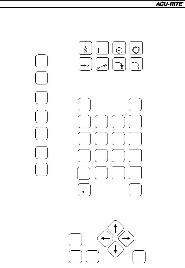
Keypad Layout
Milling Functions
Main
Function Keys
INFO
These let you set up the MILLPWR, get
information about SET
what you are doing, switch between program (PGM) and
UP
DRO, and “USE” the
VIEW
milling functions as steps in a program.
TOOL |
RECT |
CIRCLE |
HOLES |
With these keys, you define |
|
the operations you want |
|||||
|
|
|
|
||
|
|
|
|
MILLPWR to perform. |
|
|
|
|
|
These operations end up |
|
POS |
LINE |
ARC |
BLEND |
as “steps” in a program, or |
|
|
|
|
|
you can run just one of |
them at any time.
Numeric Keypad
and Calculator
ABS
CALC
INC
PGM
7 |
8 |
9 |
/ |
DRO |
|
|
|
4 |
5 |
6 |
X |
CANCEL |
2 |
3 |
- |
1 |
|||
USE |
0 |
+/- |
+ |
. |
DEL |
ENTER |
|
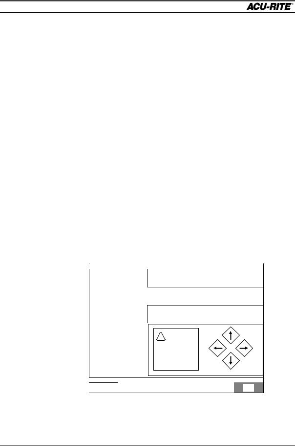
Cursor and Motion Control Keys
Enter all numerical values with these keys. When you’re entering dimensions, you can specify
absolute or incremental.
The handy 4-function calculator can be used at any time. Trig and geometry assistance
is available with a press of the CALC key.
Press GO to run your program, and STOP to stop it. The FEED keys let you adjust the cutting speed on the fly.
FEED
+
FEED
STOP GO
-
Operation Manual |
Page 1-3 |

INTRODUCTION
MILLPWR
The cursor keys help you navigate around the screen while you are using MILLPWR.
Page 1-4 |
Operation Manual |
INTRODUCTION
MILLPWR
2
3
4
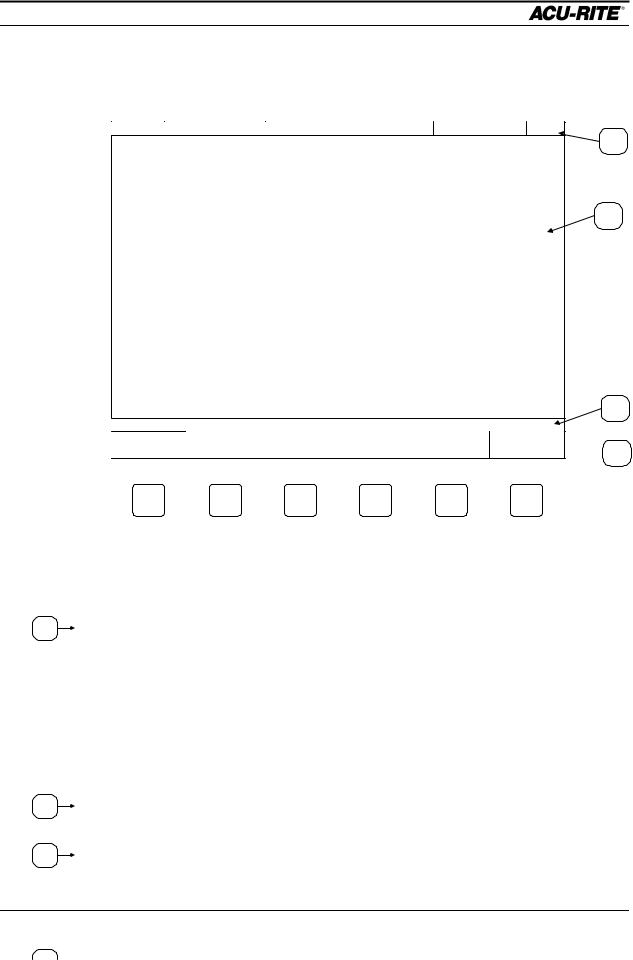
Screen Layout
The MILLPWR display screen is divided into four sections.
SERVO OFF FEED |
0 100% |
TOOL: |
SCALE 1.0000 |
INCH |
1
2
3
ZERO X ZERO Y ZERO Z DATUM
MOVE
TABLE  4
4
Status bar - displays the servo motor status (on/off), feed rate, current tool, scale, and inch/mm display view.
Information screen - displays information for the job being performed.
∙Used as a readout, the screen will display the current location for each axis.
∙When programming, a list of milling operations and part view graphics will be displayed.
∙To calculate data geometrically, lines and arcs can be constructed and displayed.
Message line - operator prompts and messages will appear here.
Softkeys - variable key functions appear here; functions are selected by |
pressing |
the hard key directly below the softkey message. |
|
Operation Manual |
Page 1-5 |
1

INTRODUCTION
MILLPWR
Saving, Backing Up, and Creating Directories for Programs
If you're writing a long program, don't wait until the end to save your work. Frequent saving reduces the risk of losing work due to a power interruption.
When you begin to create programs for your MILLPWR to run, you can save your programs in any of three places—on MILLPWR’s internal hard disk drive, on a 3 ½” floppy disk, or on your PC’s hard disk drive. Saving your work means it will not be lost if the MILLPWR is turned off or if there is a power failure.
Your MILLPWR is also equipped with a backup feature that enables you to make duplicate copies of your saved programs. We recommend backing up your work as an extra precaution against accidental deletions, hard disk drive failures, or other problems that may prevent you from recovering your original files. Backing up your programs takes only a few moments—and will save you valuable time if a problem
does occur.
And as you save and back up your programs, you can neatly organize them in any of the three default directories (“MILLPWR,” “A:,” and “REMTSTOR”) or in personalized directories you create on your own.
For more details about how to save programs, back up files, and create directories, refer to the Programming section.
Note: Before you save or back up programs on your PC’s hard disk drive, refer to the Remote Storage and System Setup sections for setup instructions.
Emergency Table Stop Button
The large red button on the front of the MILLPWR operator console is the emergency TABLE STOP. In the event of a malfunction or programming error, press the emergency TABLE STOP button to disengage the servo motors. Disengaging the servos will cause all table movement to stop.
WARNING
Pressing the emergency TABLE STOP button will NOT stop the rotation of the cutting tool unless your machine has been specifically wired to do so. Therefore, in the event of an emergency, if your machine has not been wired to stop the rotation of the cutting tool, be prepared to raise the quill in addition to pressing the emergency
TABLE STOP button.
Page 1-6 |
Operation Manual |
INTRODUCTION
MILLPWR
Conventions
Axis Conventions
Cartesian Coordinates
When programming a part using MILLPWR, table movement and tool motion are determined by the use of positive or negative numbers. MILLPWR has been factory set with the following positive and negative directions for X, Y, and Z:
X-axis: the table will move to the left, with tool motion to the right, for positive positions.
Y-axis: the table will move toward you while tool motion is away from you for positive positions.
Z-axis: quill movements up (away from the table surface) are for positive positions.
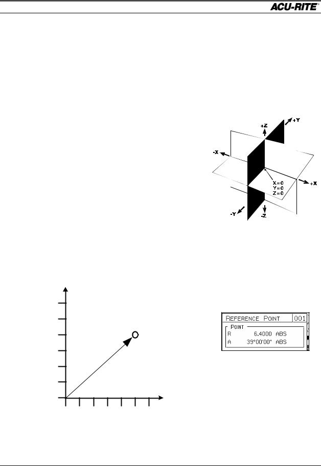
Polar Coordinates
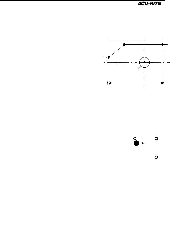
The polar radius (R), is the distance from datum (absolute zero) to a point. The polar angle (A), is formed by the X-axis and the radius, positive counterclockwise. The angle is always measured from the positive X-axis.
6 |
|
|
|
|
|
|
5 |
|
|
|
|
|
|
4 |
|
|
|
|
|
R=6.4 |
|
|
|
|
|
A=39° |
|
|
|
|
|
|
|
|
3 |
|
|
|
|
|
|
2 |
|
|
|
|
|
|
1 |
|
|
|
|
|
|
0 |
|
|
|
|
|
|
0 |
1 |
2 |
3 |
4 |
5 |
6 |
Operation Manual |
Page 1-7 |
INTRODUCTION
MILLPWR
Absolute / Incremental
Dimensions you enter from the print can be either absolute or incremental.
|
|
|
|
|
|
|
|
|
Absolute dimensions are measured from the datum which is the workpiece zero. |
||||||
|
|
|
|
|
|
|
|
|
Incremental dimensions are measured from one point to another. |
||||||
|
|
+Y |
|
|
|
|
|
|
Holes A and B are dimensioned as absolute, but hole C is |
||||||
|
|
|
|
|
|
|
|
dimensioned incrementally from A. |
|||||||
|
|
|
|
|
|
|
|
|
|
|
|
|
|
|
|
|
|
|
|
|
|
|
|
|
|
|
|
When entering these dimensions in the MILLPWR, we |
|||
|
|
|
|
|
|
4 |
|
|
|
|
|
|
|||
|
|
|
|
|
|
|
|
|
|
|
|
|
|
|
would say: |
|
|
|
|
|
|
|
A |
|
B |
C |
|
Hole A: X = 2.000 ABS |
|||
|
|
|
|
|
|
|
|
|
|||||||
1.5 |
|
|
|
|
|
|
|
|
|
|
|
|
Hole B: X = 4.000 ABS |
||
|
|
|
|
|
|
|
|
|
|
|
|
|
|
|
|
|
|
|
|
|
|
|
|
|
|
|
|
|
|
+X |
Hole C: X = 3.625 INC from hole A |
|
|
|
|
|
|
|
|
|
|
|
|
|
|
||
|
|
|
|
|
|
2 |
|
|
3.625 |
|
|
It will often be easier to describe a location in terms of |
|||
|
|
|
|
|
|
|
|
|
|
|
|||||
|
|
|
|
|
|
|
|
|
|
|
|
|
|
|
|
|
|
|
|
|
|
|
|
|
|
|
|
|
|
|
incremental dimensions than it would be to calculate the |
|
|
|
|
|
|
|
|
|
absolute coordinates of a point. |
||||||
Both absolute and incremental dimensions can be used on the same workpiece. For example, Hole C has the dimensions X = 3.625 INC from hole A, Y = 1.5 ABS.
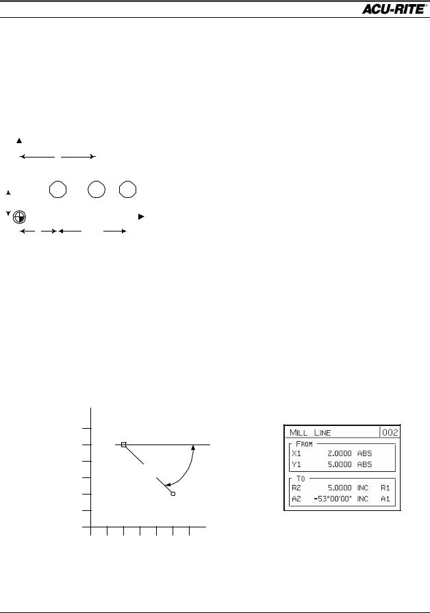
Example: Polar and Incremental
Here is how to enter the angle of a line:
If your drawing provides the angles from one end, you need to use polar and incremental. The end of the line is measured incrementally from the beginning of the line.
6 |
P 1 (From) |
|
|
|
|
|
|
|
|
|
|
||
5 |
|
|
|
|
|
|
4 |
|
|
|
|
|
- 53° |
|
|
|
|
5.0 |
|
|
3 |
|
|
|
|
|
|
|
|
|
|
|
|
|
2 |
|
|
|
|
|
|
1 |
|
|
|
|
P2 (To) |
|
|
|
|
|
|
|
|
0 |
|
|
|
|
|
|
0 |
1 |
2 |
3 |
4 |
5 |
6 |
Page 1-8 |
Operation Manual |

INTRODUCTION
MILLPWR
Notice that if you don’t use incremental coordinates, Point 2 will be incorrect because it will be measured from the datum instead of from Point 1.
Operation Manual |
Page 1-9 |

INTRODUCTION
MILLPWR
BLANK PAGE
Page 1-10 |
Operation Manual |

DRO
MILLPWR
DRO FUNCTIONS
Start-Up
Power Up
∙Make sure the power switch on the back of the Operator’s Console is on.
∙Turn the on/off switch on the side of the controller cabinet ON.
After the program has loaded, the following screen will appear:
SERVO OFF |
FEED 0 100% |
TOOL: |
|
|
SCALE 1.0000 |
INCH |
||
|
|
|
X |
INC |
0.0000 |
ABS |
||
|
|
|
|
|||||
|
|
|
0.0000 |
|
||||
|
|
|
|
|
|
|
||
|
|
|
Y 0.0000INC |
0.0000 ABS |
||||
|
|
|
|
|
|
|
|
|
|
|
|
Z |
INC |
0.0000 |
ABS |
||
|
|
|
|
|||||
|
|
|
0.0000 |
|
||||
|
|
|
|
|
|
|
|
|
ZERO X |
ZERO Y |
ZERO Z |
|
DATUM |
MOVE |
|
TABLE |
||||
|
|
|
|
|
|
|
|
|
|
|
|
DRO stands for “digital readout”.
This is called the “DRO” screen. It shows you the current tool position. Here you can use several DRO functions to set up your job. In fact, you can use this as a normal DRO when you use your machine manually.
Operation Manual |
Page 2-1 |
DRO
MILLPWR
Finding Home
The ACU-RITE’s ENC150 precision glass scales included with your MILLPWR system are different from standard ENC150 glass scales because they have only one reference mark. The reference mark will be located between five and eight inches from the centerline of your scale. The reference mark will most likely be found in the positive count direction for both the X and Y axes; however, it may be found in the negative count direction depending upon how the scale(s) are mounted.
MILLPWR must find these reference marks after power-up in order to establish the farthest table travel, so you won’t crash the table. You must find home before you can run a program.
Once you are familiar with where the reference marks are, you can use the “MOVE TABLE” function to get close to them before you press "FIND HOME".
To find home, press the DATUM softkey, then the FIND HOME softkey. The table will move, one axis at a time, to find the reference positions.
If the table moves until it hits the hard stops and the servo motor stops, it means the table was already positioned past the home position. Use the handcranks to move the table away from the end and press FIND HOME again. Should the FIND HOME softkey be pressed immediately after home has been found, the table will move to the hard stops and the servo motors will disengage.
After home has been found, the DRO display will change. The absolute display shows the tool position from the most recent datum.
DATUM is a term for “workpiece zero” or “absolute zero”.
Page 2-2 |
Operation Manual |
DRO
MILLPWR
DRO Functions
You can’t change to metric if you have an “inch” program active, and vice versa.
Reset an Axis
Pressing the ZERO X, ZERO Y, or ZERO Z softkey will zero the incremental position of that axis.
Inch - Metric
To change the measurement system between inches and metric units, press the SETUP key to get the INCH and MM softkeys. Select the system you want, and
press USE NEW SETTINGS.
Move Table
This function lets you move the table rapidly using the arrow keys. Pressing the MOVE TABLE softkey will caution you that the arrow keys no longer move around the screen, but will instead move the table.
Note that the arrow keys will move the table!
SERVO ON |
FEED |
0 100% |
TOOL: |
SCALE 1.0000 |
INCH |
X 0.000INC |
0.0000ABS |
Y 0.000INC |
0.0000ABS |
Z 0.000INC |
0.0000 ABS |
! CAUTION |
|
ARROW KEYS |
|
WILL MOVE TABLE |
|
PRESS CANCEL WHEN FINISHED MOVING TABLE.
MOVE
TABLE
Operation Manual |
Page 2-3 |

DRO
MILLPWR
The table moves in the direction of the arrows. You can move in both X and Y at the same time.
MOVE TABLE AWAY
FROM YOU
It’s a REALLY good idea to fold in the handcrank handles before moving the table!
MOVE |
MOVE |
TABLE |
TABLE |
LEFT |
RIGHT |
|
MOVE TABLE |
|
TOWARDS YOU |
While the MOVE TABLE
softkey is pressed, the servo motors are on. Press it again to turn them off.
Establishing a Datum
A datum is a reference point that you establish as the workpiece zero. You need to set a datum for each job. The location on the workpiece that is to be used as the datum will be determined by the way the part is dimensioned on the blueprint. In general, you should select a datum location so that you may enter most dimensions directly, without calculations.
The datum position is not lost at power-down, so you can quit in the middle of a job at night and easily resume it the next morning.
The simplest datum location to set is where you can position the tool exactly at that location in all three axes.
∙ |
Position the |
|
|
|
|
|
|
|
|
|
|
|
|
|
|
|
|
SERVO OFF |
FEED |
0 100% |
TOOL: |
|
|
SCALE |
1.0000 |
INCH |
|||||||||
|
workpiece so that the |
|
|
SET DATUM |
|
|
|
X 0.0000INC |
|
0.0000 |
ABS |
||||||
|
datum point is directly |
|
|
|
|
|
|
|
|
||||||||
|
|
|
|
|
|
|
|
|
|||||||||
|
|
X: |
|
|
|
|
|
|
|||||||||
|
|
|
|
Y 0.0000INC |
|
0.0000 |
|
||||||||||
|
beneath the tool. This |
|
Y: |
|
|
|
|
ABS |
|||||||||
|
|
|
|
|
|
|
|
|
|
|
|
|
|
|
|
||
|
point might be a |
|
|
|
|
|
|
|
|
|
|
|
|
|
|
|
|
|
|
|
|
|
|
|
|
|
Z 0.0000INC |
|
0.0000 ABS |
||||||
|
corner, the center of a |
|
Z: |
|
|
|
|
||||||||||
|
|
|
|
|
|
|
|
|
|
||||||||
|
bolt hole pattern, etc. |
|
|
|
|
|
|
|
|
|
|
|
|
|
|
|
|
|
|
|
|
|
|
|
|
|
|
|
|
|
|
|
|
|
|
∙ |
Press the DATUM |
|
|
|
|
|
|
|
|
|
|
|
|
|
|
|
|
|
softkey and the Set |
|
|
|
|
|
|
|
|
|
|
|
|
|
|
|
|
|
Datum entry form will |
|
|
|
|
|
|
|
|
|
|
|
|
|
|
|
|
|
appear. |
|
|
|
|
|
|
|
|
|
|
|
|
|
|
|
|
∙ |
Press the X=0, Y=0, |
|
|
|
|
|
|
|
|
|
|
|
|||||
ENTER THE NEW ABSOLUTE POSITION OF THE TOOL CENTER. |
|
|
|
|
|
|
|||||||||||
|
X = 0 |
|
Y = 0 |
Z = 0 |
|
FIND |
|
USE |
MOVE |
||||||||
|
and/or Z=0 softkey(s) |
|
|
|
HOME |
|
PROBE |
TABLE |
|||||||||
|
|
|
|
|
|
|
|
|
|
|
|
||||||
|
|
|
|
|
|
|
|
|
|
|
|
|
|
|
|
|
|
|
|
|
|
|
|
|
|
|
|
|
|
|
|
|
|
|
|
|
to establish workpiece zero. |
|
|
|
|
|
|
|
|
|
|
|
|||||
∙Press USE to lock in the workpiece zero.
Page 2-4 |
Operation Manual |
DRO
MILLPWR
If you can’t position the tool center right at the datum, you’ll need to enter a value for each axis. The value to use is the absolute position of the tool center from the new datum. For one axis at a time, position the tool to a known location, such as the edge of the workpiece. Without moving the tool, enter the desired location of the tool center and press ENTER. Then move to position the next axis. When all are entered, press USE.
The MILLPWR calculator helps a lot here---To set the datum for the X axis, enter:
0.3875/2+.005. Then, since the tool center is left of the datum, change the sign.
DISTANCE TO
ENTER
.005 SHIM 
0.3875 TOOL
 +
+
While you are setting the datum, you can use the MOVE TABLE softkey to help you with long moves.
Using A Probe
You may use a touch probe or edge finder to get very accurate edge locations. Make sure the diameter of the probe is correct (it’s found in the SET-UP list). Install the probe and connect it to the back of the Operator Console. Then, for one axis at a time, enter the absolute position of the edge to be touched into the datum form, press the USE PROBE softkey, and move the table slowly until the probe touches the workpiece. When the probe touches, the USE PROBE softkey will release. Press the USE key to set the absolute position of each axis.
TIP: |
|
Right after you find |
|
home, you |
|
can move quickly to |
|
your previous datum |
|
using the position |
POS |
function: |
GO |
Operation Manual |
Page 2-5 |

DRO
MILLPWR
One Time Milling Functions
Any of the milling functions, except BLEND, can be used “one time” without creating a program. Press the desired milling function key, fill in the information, and press
GO.
The information for each function will be remembered for the next time you use it.
Each function is described in the Program Steps section.
For many of the milling functions, such as a pocket, you will need to set the proper tool diameter. You can use the TOOL key as a one-time function to do this.
Page 2-6 |
Operation Manual |

PROGRAMMING
MILLPWR
PROGRAMMING
Programming Considerations
Depth of Cut
Since the vertical Z-axis is not controlled by a servo motor, you must make changes to the depth of cut manually.
You don’t have to program the depth, but if you do, MILLPWR will preset the programmed value into the DRO for you. Then, when it’s time, will show you the DRO and ask you to set the depth.
If you are not programming depth, leave it set to 0.
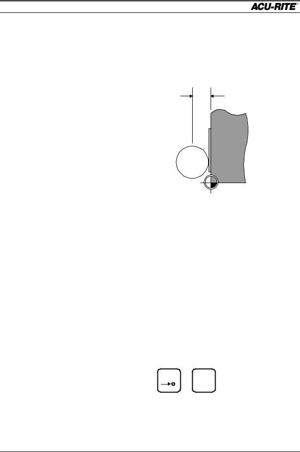
Tool Offset
With MILLPWR, you never have to worry about the actual tool path. Because of MILLPWR ’s tool radius compensation capability, you program only the actual part dimensions. When you program a line, arc, or frame, use the TOOL OFFSET field to tell
which side of the cut you want the tool to be on.
Picture yourself standing behind the tool as it is moving. If the tool is on the left of the workpiece, use “left” offset. If the tool is to the right of the workpiece, use “right” offset.
By using left and right offsets,
you can program the |
LEFT OFFSET |
RIGHT OFFSET |
dimensions of the part as |
|
|
found on the blueprint. |
|
|
MILLPWR will take care of |
|
|
all cutter radius |
|
|
compensation. You do not |
|
|
have to program the tool |
|
|
path. |
|
|
If you use “center” offset, the programmed dimensions are for the center of the tool.
For some milling functions, like Frame and Arc, “inside” and “outside” offsets help you visualize where the tool is.
Operation Manual |
Page 3-1 |
PROGRAMMING
MILLPWR
“From” and “To” Points
FROM |
T O |
MILLPWR lines and arcs are defined by both FROM and TO points. MILLPWR will automatically go to the start point before it asks you to set the depth.
|
FROM |
|
|
|
|
|
X1 |
ABS |
|
Y1 |
ABS |
|
|
|
|
TO |
|
|
|
|
|
X2 |
ABS |
|
Y2 |
ABS |
|
|
|
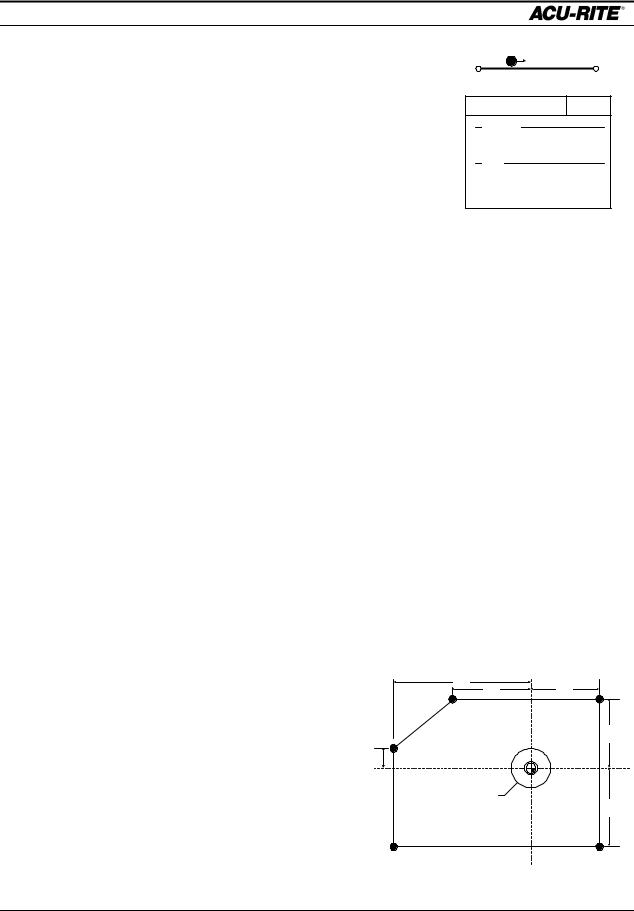
Datum Selection
The datum is the point where all absolute dimensions are measured from. You must look at the blueprint of the part and decide what to use as a datum. You should pick a point which will let you enter most of the dimensions directly, without calculations. However, any point you select will give the same results.
Absolute and Incremental Dimensions
To help you enter dimensions directly from the blueprint, MILLPWR allows direct entry of both absolute and incremental dimensions. Any dimension measured from the point you select as the datum is called absolute.
A dimension measured from any other point is called incremental. This “other point” is called the incremental reference point.
For the part drawn below, if we put the datum in the center of the hole (point F), all dimensions are absolute.
|
|
|
|
|
|
7.123 |
|
|
Point |
|
X |
Y |
|
D |
4.893 |
3.421 |
C |
|
|
|
|
|||||
A |
-7.123 |
ABS |
-3.936 |
ABS |
|
|
|
3.603 |
B |
3.421 |
ABS |
-3.936 |
ABS |
E |
|
|
|
|
|
|
||||||
|
|
|
|
C |
3.421 |
ABS |
3.603 |
ABS |
D |
-4.893 |
ABS |
3.603 |
ABS |
1.011
F
2.96 DIA
THRU HOLE
3.936
E |
-7.123 |
ABS |
1.011 |
ABS |
F |
0.00 |
ABS |
0.00 |
ABS |
A B
Page 3-2 |
Operation Manual |
PROGRAMMING
MILLPWR
If we use point A as our datum, many of the given dimensions are incremental because they are measured from the incremental reference point F and not from the datum.
|
|
|
|
|
|
7.123 |
|
|
Point |
|
X |
Y |
|
D |
4.893 |
3.421 |
C |
|
|
|
|
|||||
A |
0.00 |
ABS |
0.00 |
ABS |
|
|
|
3.603 |
B |
3.421 |
INC F |
0.00 |
ABS |
E |
|
|
|
|
|
|
||||||
|
|
|
|
|||||
|
|
|
|
|
1.011 |
|
|
|
C |
3.421 |
INC F |
3.603 |
INC F |
|
|
F |
|
|
|
|
|
|
|
|
||
D |
-4.893 |
INC F |
3.603 |
INC F |
2.96 DIA |
|
|
|
THRU HOLE |
||||||||
|
|
|
|
|
||||
3.936
E |
0.00 |
ABS |
1.011 |
INC F |
F |
7.123 |
ABS |
3.936 |
ABS |
A |
B |
|
Continuous Milling
MILLPWR will display marks to the right of each program step number for continuous contours.
When you program a continuous contour made up of lines and arcs, |
MILLPWR |
||||
will mill the contour without stopping. MILLPWR will detect a continuous contour |
|||||
automatically. There are no special keypresses or |
different functions to learn. |
||||
For lines and arcs to be continuous, they must: |
FROM |
TO |
|||
∙ have the same Z depth, |
|
|
|
|
FROM |
|
|
|
|
||
|
|
|
|
|
|
|
|
|
|
|
|
∙be cut with the same tool,
∙ |
TO |
be cut on the same side, |
∙ and, of course, they must “touch”--the end of one must be the same as the start of the next.
When you follow one line (or arc) with another, MILLPWR assumes that you want them to be connected. It automatically fills in the FROM point, Z depth, and tool offset. All you have to do is fill in the TO point, and press USE.
You can have different feedrates within a continuous contour by entering the feedrates you want in each step of the contour.
Operation Manual |
Page 3-3 |
PROGRAMMING
MILLPWR
Creating a Program
Press the PGM key, and the following program screen appears.
SERVO OFF |
FEED |
0 100% |
TOOL: |
SCALE 1.0000 |
INCH |
CURRENT PROGRAM
END OF 0
PROGRAM |
CLEAR |
EXPLODE |
MORE |
|
RUN |
FUNCTIONS |
PROGRAM |
STEPS |
|
OPTIONS |
|
|
|
||||
|
|
|
|
|
|
You create a program by creating a list of milling steps to be performed. As you add to your list, each step will be drawn immediately on the screen so you can see a picture of your part in progress.
∙To enter a milling step, press the appropriate milling function key. The function you select will appear in the program listing, and you can enter the information
SERVO |
OFF FEED |
0 |
100% |
TOOL: |
|
|
SCALE |
1.0000 |
INCH |
|
CURRENT PROGRAM |
|
MILL ARC |
002 |
|
|
|
||
001 |
SET TOOL |
|
|
FROM |
|
|
|
|
|
002 |
X MILL ARC |
|
|
X1 |
|
ABS |
|
|
|
|
|
|
|
|
|
|
|
||
|
|
|
|
Y1 |
|
ABS |
|
|
|
|
|
|
|
TO |
|
|
|
|
|
Program |
|
|
|
X2 |
|
ABS |
|
|
|
|
|
|
Y2 |
|
ABS |
|
|
|
|
Step |
|
|
|
DEPTH |
|
|
|
|
|
Listing |
|
|
|
Z |
|
ABS |
|
|
|
|
|
|
|
RADIUS |
|
|
|
|
|
|
|
|
|
DIRECTION |
|
|
|
|
|
|
|
|
|
|
CCW |
|
|
|
|
|
|
|
|
TOOL |
|
|
|
|
|
|
|
|
|
|
0.500 |
DIAMETER |
|
|
|
|
|
|
|
|
FL END ML |
TYPE |
|
|
|
|
|
|
|
|
CENTER |
OFFSET |
|
|
|
|
2 OF 2 |
|
|
FEED |
10 |
IPM |
|
|
|
|
|
|
|
|
|
|
|
|
|
|
|
|
|
|
|
TEACH |
POLAR |
|
MORE |
|
|
|
|
|
POSITION |
|
|||
|
|
|
|
|
|
|
|
||
Enter information about the arc into this form.
Page 3-4 |
Operation Manual |
PROGRAMMING
MILLPWR
describing the step into the form.
∙After entering all the data for a step, press the USE key to accept the data. This updates the picture and moves down for the next step.
SERVO OFF |
FEED |
0 100% |
TOOL: |
SCALE 1.0000 |
INCH |
CURRENT PROGRAM
001 SET TOOL
002 MILL ARC
END OF 2
PROGRAM |
CLEAR |
EXPLODE |
MORE |
|
RUN |
FUNCTIONS |
PROGRAM |
STEPS |
|
OPTIONS |
|
|
|
||||
|
|
|
|
|
|
∙To change a step, use the arrow keys to move to the step and press USE or ENTER.
When you have made your changes, press USE to put the changed step back into the program.
∙To delete a step, move to the step and press the DEL key.
∙To insert a step, move to where you want the new step to go, and press the new milling function key.
If you decide not to use a milling function that you have selected, press the CANCEL key.
In addition to the milling functions, the MORE STEPS softkey lets you pick from a number of other useful steps, such as REPEAT and ROTATE. All steps are described in the Program Steps section.
Operation Manual |
Page 3-5 |
 Loading...